Table of Contents
Advertisement
Quick Links
Advertisement
Table of Contents

Related Manuals for Datavideo BC-200T


Summary of Contents for Datavideo BC-200T
- Page 1 4K HDBaseT BLOCK CAMERA BC-200T Instruction Manual...
-
Page 2: Table Of Contents
Table of Contents FCC COMPLIANCE STATEMENT ........4 WARNINGS AND PRECAUTIONS ........4 WARRANTY ..............6 ............6 TANDARD ARRANTY ............. 6 HREE ARRANTY DISPOSAL ..............7 1. INTRODUCTION ............8 ................ 8 EATURES 2. SYSTEM DIAGRAM ..........10 3. CONNECTIONS ............11 ............ - Page 3 Disclaimer of Product & Services The information offered in this instruction manual is intended as a guide only. At all times, Datavideo Technologies will try to give correct, complete and suitable information. However, Datavideo Technologies cannot exclude that some information in this manual, from time to time, may not be correct or may be incomplete.
-
Page 4: Fcc Compliance Statement
7. This product should only be operated from the type of power source indicated on the marking label of the AC adapter. If you are not sure of the type of power available, consult your Datavideo dealer or your local power company. - Page 5 9. If an extension cord must be used with this unit, make sure that the total of the ampere ratings on the products plugged into the extension cord do not exceed the extension cord rating. 10. Make sure that the total amperes of all the units that are plugged into a single wall outlet do not exceed 15 amperes.
-
Page 6: Warranty
• The product warranty period begins on the purchase date. If the purchase date is unknown, the product warranty period begins on the thirtieth day after shipment from a Datavideo office. • Damage caused by accident, misuse, unauthorized repairs, sand, grit or water is not covered under warranty. -
Page 7: Disposal
• The three-year warranty must be registered on Datavideo's official website or with your local Datavideo office or one of its authorized distributors within 30 days of purchase. Disposal For EU Customers only - WEEE Marking This symbol on the product or on its packaging indicates that this product must not be disposed of with your other household waste. -
Page 8: Introduction
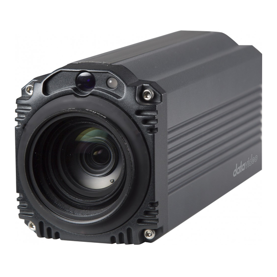
1. Introduction The BC-200T Block Camera is a 4K (3840x2160, UHD) camera with an infra-red remote control. It can be used for UHD high quality shooting in an environment where space is limited. The BC-200T equips the HDBaseT technology to achieve long-distance ultra-high video/audio, power, control, and Ethernet signals transmission over a single Ethernet cable. - Page 9 Users can save up to 10 preset camera settings for future use. • Users can control up to 28 BC-200T devices simultaneously via the RMC-180 PTZ camera remote control unit (including White Balance, Focus, Iris, Shutter Speed, Zoom, Zoom Speed, Save Preset, Recall Preset) P.S.
-
Page 10: System Diagram
2. System Diagram... -
Page 11: Connections
3. Connections Camera Front View IR Receiver Receives signal from the IR remote control. Tally Light As the camera is booting, the tally light stays solid green and turns solid red for about three seconds just before the boot is complete. The tally light remains solid green after the camera finishes booting. -
Page 12: Camera Rear Panel
Camera Rear Panel HDMI Output Video output connected to HDMI port of the monitor. - Page 13 BC-200T cameras on one channel port, which means the RMC-180 is able to control up to 28 units of the BC-200T with its four channel ports at the same time. 12V DC Power DC in socket connects the supplied 12V PSU. The...
- Page 14 Indicator OFF: Power OFF HDBaseT Connect an Ethernet cable Control Port from the HDBaseT port of the BC-200T to the HDBaseT port of the HBT-11 HDBaseT receiver to transmit the UHD video/audio, power, DVIP and Ethernet signals within one cable.
-
Page 15: Receiver Box Front Panel
Receiver Box Front Panel HDBaseT Port Connect an Ethernet cable from the HDBaseT port on the rear panel of the BC-200T to this port RS-232/RS-422 Interface (Phoenix Terminal) Connects to external RS-232/RS-422 device. RX: Receiver PIN (differential pair if RS-422 is enabled) -
Page 16: Receiver Box Rear Panel
Receiver Box Rear Panel HDMI OUT HDMI port for video output. DVIP Port Connects to Ethernet switch or router, serving as a communication port between the network and the HBT-11 receiver. 48V DC IN 48V DC power input connection Power LED Indicator ON: Power connected OFF: Power disconnected... -
Page 17: Ir Remote Control
4. IR Remote Control Use the IR remote control that comes with the product package to operate the BC-200T Block Camera. The IR remote control functions are described in the table below. - Page 18 Item Description Reset Press RESET or XYZ button to return the camera lens to the default zoom position (Z:0000). Group Not Applicable Select CAM1-CAM4 in a multi- camera environment Press Camera Select buttons to select a camera from Camera 1 to Camera 4 in a multi-camera environment.
- Page 19 Set up Preset Point Press any of the POSITION buttons 1~50 and then press SET button. Recall saved settings Press any of the POSITION buttons 1~50 and then press PRESET button. Set up Group Scan mode Press any of the POSITION buttons 1~8 and then press GROUP button.
- Page 20 P/T Speed Adjust Pan/ Tilt Speed Not Applicable Make the subject appear brighter Adjust the iris opening (aperture), to control the amount of light coming through the lens (i.e. the "exposure"). Press IRIS+ button to Auto Iris Control enlarge the iris opening to allow more light to come in so that the subject appears brighter and press IRIS- button to shrink the iris...
- Page 21 Enter/ Exit Camera Menu Press the MENU button to Enter or Exit the Camera OSD Menu Zoom Zoom In/Out Press either (T) TELE button to zoom Buttons in on the subject such that it appears to be close to the camera or (W) WIDE button to zoom out from the subject such that it appears to be far away from the camera.
-
Page 22: Osd Menu Options
5. OSD Menu Options On-Screen Menu allows the user to change various camera settings such as shooting conditions and the system setup. Press Menu button on the IR remote control to enter the on-screen menu as shown below. [MAIN MENU] 1: Camera Setting 2: Memory 3: Video Output... -
Page 23: Video Mode
Selection Way This option configures how you can select the video mode. Enabling DIP SW 8 allows you to use the DIP switch to set the video mode instead of the 3. Video Output remote control. Pattern Pattern generates color bars for color calibration. - Page 24 15. HR Mode 16. WD Mode 17. Digital Zoom 18. Low Delay 19.Escape First Level Second Level Third Level Fourth Level Sub-Option Main Sub-Options Parameters Parameters Descriptions Options NAME DISPLAY SW ON/OFF UPPER LEFT 1. Camera LOWER RIGHT Name POSITION UPPER RIGHT LOWER LEFT ESCAPE...
- Page 25 AF SENSITIVITY NORMAL FOCUS SPEED ESCAPE AUTO IRIS MODE MANUAL F1.8 F2.0 F2.4 F2.8 F3.4 F4.8 5. Iris Manual IRIS LEVEL F5.6 F6.8 F9.6 CLOSE ESCAPE AGC MODE ON/OFF 0dB~GAIN MANUAL GAIN LIMIT in steps of 3 dB 9 dB 12 dB 15 dB 6.
- Page 26 DNR(AT AGC ON) DNR LEVEL ESCAPE ESCAPE FOG CORRECTION ON/OFF 7. Fog Correction ESCAPE 8. Aperture 0~15 9.Color Gain 0~14 10. Exposure 0~14 Comp. OFF/ON 11. Backlight (This option is Correct enabled after AGC is turned on) 12. Day/Night Mode COLOR 1/25 1/50...
- Page 27 (This option is enabled after AGC is turned on) 16. WD Mode 17. Digital Zoom 18. Low Delay :set 19. Escape 1. FOCUS= User- Defined 1.ZOOM= - - - - 2. IRIS= User- 2. ZOOM= - - - - Defined 3.
- Page 28 4. Escape RS-422, SW (Configurable 1. Remote using DIP switch DVIP, SW bit 4 ONLY) BY MENU CAMERA ID MODE BY SWITCH CAMERA ID 9600 2. Set RS-422 19200 RS-422 BAUD RATE 38400 115200 ESCAPE 4. Remote 9600 Control 19200 DVIP BAUD RATE 38400 3.
- Page 29 DEBUG DVIP DEBUG DEBUG FRAME TEST ESCAPE STATUS TEST ESCAPE 4. Reset All YES/NO SW VERSION ESCAPE MB CPU V00.39c 5. Update Software UPDATE ALL YES/NO ESCAPE 6. Escape 6. Escape...
-
Page 30: Dip Switch Settings
6. DIP Switch Settings DIP SW 1/2/3 VISCA ID ON / OFF / OFF VISCA-ID 1(default) OFF / ON / OFF VISCA-ID 2 ON / ON / OFF VISCA-ID 3 OFF / OFF / ON VISCA-ID 4 ON / OFF / ON VISCA-ID 5 OFF / ON / ON VISCA-ID 6... -
Page 31: Dvip Configuration Tool
After the software download is complete, please follow the steps outlined below to set up the DVIP Configuration Tool. Step 1: Connect your PC directly to the DVIP port of the BC-200T camera. If there is more than one BC-200T camera, please connect all BC-200T cameras to an Ethernet router. -
Page 32: Device Search
Note: Please make sure that the selected network interface card is within the same IP range as the connected BC-200T camera or else it would be impossible for the DVIP Configuration Tool to find the connected DVIP device. Step 2: After logging in the interface card, the user will be able to view the device name, MAC address and number of device. -
Page 33: Clearing Device List
Clearing Device List On the tool bar, users are allowed to clear the device list by clicking the “Device List Clear” button. -
Page 34: Detailed Device Network Information
Detailed Device Network Information After selecting a device in the left column, you will then be able to view each device information on the right, including name, MAC, IP address and etc. Modify Device Information and Write to Device The user is allowed to modify the device information in the right column such as device name, MAC, IP address and etc. -
Page 35: Switch To Other Network Interface
Switch to Other Network Interface To select other network interface cards, click Network Network Card... -
Page 36: Language Selection
Language Selection On the tool bar, select a language: Traditional Chinese, Simplified Chinese or English... -
Page 37: Rmc-180 Camera Control Unit
8. RMC-180 Camera Control Unit The RMC-180 PTZ Camera Controller is designed to control at least 4 Datavideo Pan Tilt Zoom (PTZ) cameras such as the BC-200T. The four RJ-45 ports provided on the RMC-180 rear serve to connect BC cameras, thus allowing the user to use any RJ-45 cable to connect the RMC-180 to the RS-422 port located on the BC camera’s rear panel. -
Page 38: Connection To Camera Via Hbt-11
Connection to Camera via HBT-11 To use the RMC-180 PTZ Camera Control Unit to control the BC-200T camera behind the HBT-11 Receiver Box, please connect the RMC-180 to the HBT-11 using the RS-422 wiring scheme as shown below. The cabling required needs to be designed specifically and can be made by yourself or a competent technician. -
Page 39: Firmware Upgrade
9. Firmware Upgrade Copy MB CPU image files into the root directory of a USB hard drive (<16 GB) and insert it into the USB Upgrade port (You may use a USB extension cord). Open the OSD menu using IR remote control by pressing the MENU button. -
Page 40: Dimensions
10. Dimensions... - Page 41 All measurements in millimeters (mm)
-
Page 42: Specifications
11. Specifications Video Image Pickup Element 1/2.3” type Exmor R CMOS sensor Effective Picture Elements Approx. 8.93 Mega pixels 4K (3,840 x 2,160, UHD) 2160p / 29.97, 2160p/25 Signal System HD: 1080p59.94/50 1080i59.94/50 720p59.94/50 50%, High Sensitivity Mode Color : 0.75 lx (F1.8, AGC ON, 1/30 Min. - Page 43 Angle of View (Horizontal) 70.7 degrees (WIDE END) to 6.4 degrees (TELE END) Minimum Object Distance 10 mm (WIDE END) to 1,500 mm (TELE END) (Default: 300 mm) Video Output Video Output HDMI x 1 Control Protocol VISCA / DVIP Protocol Remote Control RS-422 &...
-
Page 44: Service And Support
It is our goal to make your products ownership a satisfying experience. Our supporting staff is available to assist you in setting up and operating your system. Please refer to our web site www.datavideo.com for answers to DATAVIDEO WORLDWIDE OFFICES common questions, support requests or contact your local office below.