Table of Contents
Advertisement
Quick Links
Advertisement
Table of Contents

Related Manuals for Datavideo PTC-140W


Summary of Contents for Datavideo PTC-140W
- Page 1 PTC-140...
-
Page 2: Table Of Contents
Table of Contents TABLE OF CONTENTS ..................2 FCC COMPLIANCE STATEMENT ................4 WARNINGS AND PRECAUTIONS ................. 4 WARRANTY ......................5 ..................5 TANDARD ARRANTY ..................6 HREE ARRANTY DISPOSAL ......................6 PRODUCT OVERVIEW ................. 8 ......................8 EATURES LOCATION AND FUNCTION OF PARTS ............9 BASIC SETUP .................... - Page 3 Further advice on the content of this manual or on the product can be obtained by contacting your local Datavideo Office or dealer.
-
Page 4: Fcc Compliance Statement
7. This product should only be operated from the type of power source indicated on the marking label of the AC adapter. If you are not sure of the type of power available, consult your Datavideo dealer or your local power company. -
Page 5: Warranty
Warranty Standard Warranty Datavideo equipment are guaranteed against any manufacturing defects for one year from the date of purchase. The original purchase invoice or other documentary evidence should be supplied at the time of any request for repair under warranty. -
Page 6: Three Year Warranty
PCIe Card are covered for 1 year. The three-year warranty must be registered on Datavideo's official website or with your local Datavideo office or one of its authorized distributors within 30 days of purchase. Disposal For EU Customers only - WEEE Marking... - Page 7 the recycling of waste electrical and electronic equipment. The separate collection and recycling of your waste equipment at the time of disposal will help to conserve natural resources and ensure that it is recycled in a manner that protects human health and the environment. For more information about where you can drop off your waste equipment for recycling, please contact your local city office, your household waste disposal service or the shop where you purchased the product.
-
Page 8: Product Overview
Product Overview The PTC-140 is a low-cost SDI/HDMI PTZ camera featuring 20x optical zoom and 10x digital zoom. The PTC-140 is also an IP camera supporting H.264 /H.265 video compression and dual stream outputs. Features 1/2.8 inch CMOS sensor. Resolution is up to 1920x1080 with frame rate up to 60fps. -
Page 9: Location And Function Of Parts
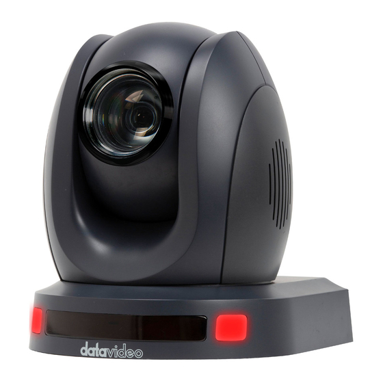
Location and Function of Parts Front of Camera Lens Built-in 1/2.8” 2.07M Pixel CMOS HD color camera with white balance control, backlight compensation, automatic gain and etc. Tally LED Tally lamp will be turned ON upon receiving the ON signal. Sensor for Remote Control Remote control IR receiver... - Page 10 Rear of Camera Power Input DC in socket connects the supplied 12V PSU. The connection can be secured by screwing the outer fastening ring of the DC In plug to the socket. LAN Port This port allows you to establish network connection with the camera. Connect an Ethernet cable from this port to the LAN port of a PC in order to monitor the camera video from the web user interface.
- Page 11 HDMI OUT The HDMI OUT allows you to connect an external HDMI monitor via an HDMI cable. 3G-SDI OUT The 3G-SDI OUT allows you to connect an external monitor via an SDI cable. Audio IN The 3.5mm audio input receives external audio. RS-422/RS-485 Interface (RJ-45) The RS-485 interface serves to connect external RS-422/RS-485 devices.
- Page 12 Bottom of Camera Tripod Screw Hole allows the user to mount the camera on the tripod. Screw Hole Screw holes for ceiling bracket mounting. For Safety Rope Ties safety rope for fixing the camera to the ceiling.
-
Page 13: Basic Setup
Basic Setup 3.1 Power-On Initialization As shown in the diagram below, after you plug in the power cord, the tally light in the front will start flashing red and will be OFF as soon as the power-on initialization is complete. The camera head should be at the HOME position with the lens facing front. -
Page 14: Hdmi Video Output
4. Click into the preview window on which the video will be displayed. HDMI Video Output Connect the HDMI OUT to an external connected monitor using an HDMI cable. 3G-SDI Video Output Connect the SDI OUT to an external connected monitor using an SDI cable. -
Page 15: Remote Control And On-Screen Menu
Remote Control and On-Screen Menu This chapter provides an overview of remote control functions and OSD menu. 4.1 Remote Control Functions... - Page 16 Function Keys Descriptions Standby Key The standby button turns ON/OFF the camera. Standby Key To reboot the camera, press the standby button for 3 seconds. After device initialization is complete, the camera head will automatically return to HOME position. Camera Select Keys To select a camera in a multi-camera environment using camera select keys (CAM1 –...
- Page 17 Function Keys Descriptions The asterisk and pound keys form various combinations with other keys to access certain functions directly. The shortcuts are listed as follows: 1. 【#】+【#】+【#】: Clear all presets 2. 【*】+【#】+【6】: Restore factory defaults 3. 【*】+【#】+【9】: Image flip along horizontal axis 4.
- Page 18 Function Keys Descriptions Manual Focus Manual Mode Pressing this key enables manual mode allowing you to adjust the camera’s focus and zoom by pressing Focus+/- and Zoom+/- keys. Focus Focus +/- Press and hold Focus+ or Focus- to adjust the focus accordingly and release as soon as the desired focus is reached.
- Page 19 Function Keys Descriptions Direction Arrow Keys Direction Arrows Press the arrow keys to move the camera head up, down, left and right. 11-13 Home Key Press Home to return the camera head to the center. Note: In the OSD menu, press Home to enter the selected option item and MENU to exit.
-
Page 20: On-Screen Menu
4.2 On-Screen Menu On-Screen Menu allows the user to modify various camera settings. Press [MENU] on the remote control to open the on-screen menu as shown below. On-Screen MENU Language Setup Camera P/T/Z Video Format Network Settings Version Restore Default Escape [↑↓] Select [←... - Page 21 Main Options Restor Video Network Language Setup P/T/Z Version Camera Settings Format Default 720P59.9 Details of all options in the on-screen menu are listed in the table below. Main Menu Sub Menu Options Sub-options English Language Simplified Chinese Auto VISCA Protocol PELCOO-D PELCCO-P...
- Page 22 Main Menu Sub Menu Options Sub-options Flicker 50Hz 60Hz Gain Limit 0~15 Closed Auto 3000K 3500K 4000K 4500K 5000K WB Mode 5500K Color 6000K 6500K 7000K Manual Onepush RG Tuning...
- Page 23 Main Menu Sub Menu Options Sub-options BG Tuning...
- Page 24 Main Menu Sub Menu Options Sub-options 100% 110% 120% Saturation 130% 140% 150% 160% 170% 180% 190% 200% High AWB Sensitivity Middle Image Brightness...
- Page 25 Main Menu Sub Menu Options Sub-options Contrast Sharpness...
- Page 26 Main Menu Sub Menu Options Sub-options Flip-H Flip-V Color B & W Mode Black & White Default 0.45 Gamma 0.50 0.55 0.63 Closed Auto Focus Mode Manual Onepush Center Focus AF-Zone Bottom High AF-Sensitivity Middle Auto Noise Reduction NR-2D...
- Page 27 Main Menu Sub Menu Options Sub-options NR-3D Dynamic Hot Pixel Default Normal Style Clarity Bright Soft Zoom by Speed Zoom Speed P/T/Z Standard Acc Curve Slow Fast Fast Preset Speed Slow Middle Positive Joystick Pan Dir Negative...
- Page 28 Main Menu Sub Menu Options Sub-options Positive Joystick Tilt Dir Negative 1080P60 1080P50 1080I60 1080I50 1080P30 1080P25 Video Format 720P60 720P50 1080P59.94 1080I59.94 1080P29.97 720P59.94 DHCP Network Settings IP Addr 192.168.x.x MCU Version Version Camera Version AF version Restore Default Restore Default (Yes/No) Note:...
-
Page 29: Professional Jargon Explanations Of The Osd Menu
4.3 Professional Jargon Explanations of the OSD Menu There are some professional jargons or nouns which are shown in the OSD menu of the PTC-140 camera, please refer to this section for realizing those jargons. Speed by Zoom: When this function is turned “ON”, at the time when the zoom-in/zoom out is beginning or it is about to reach the zoom-in/zoom- out limit or users want to stop zooming in/zooming out, the zoom-in/zoom- out speed of the camera lens will be reduced linearly. -
Page 30: Installation Instructions
Installation Instructions Note: Only mount the bracket on formwork or concrete surface. Do NOT mount the bracket on plasterboard. In your product package, you should find PA4*30 self-tapping screw x 4 PA4 plastic screw stopper x 4 PM3*5 screw x 6 ... - Page 31 Step 2: Mount the bracket’s upper plate to the ceiling Insert the four PA4 plastic screw stoppers into the ceiling as shown in the diagram below. Using four PA4*30 self-tapping screws, affix the bracket’s upper plate to the ceiling. Upper Plate of Ceiling Bracket Step 3: Affix the bracket’s lower plate to the bottom of PTC-140 As depicted in the diagram below, use three PM3*5 screws to affix the bracket’s lower plate to the bottom of PTC-140.
- Page 32 Lower Plate of Ceiling Bracket Step 4: Mount the PTC-140 Camera to the ceiling Now push the PTC-140 camera into the bracket’s upper plate in the direction as indicated by the arrow in the diagram below. Make sure the two plates click into place.
- Page 33 Step 5: Final...
-
Page 34: Network Connection
Network Connection The Ethernet port on the back panel of your PTC-140 allows you to connect to camera from the PC/Laptop with Static or dynamic IP addresses. To access and modify these network settings, you will need to login to the camera’s web interface. -
Page 35: Dhcp Mode
The default login credentials are: User Name: admin Password: admin After you have successfully login to the web interface, click “Configuration” “Ethernet” to open the network settings page on which you should be able to see a list of options allowing you to set the camera’s connection mode to DHCP or static IP. - Page 36 In order to enable the camera’s DHCP mode, simply check the DHCP checkbox to allow the router to dynamically assign an IP address to PTC-140. Click “Save” button to save the new settings then reboot PTC-140.
-
Page 37: Static Ip
Depending on your operating system, download DVIP Configuration Tool from the respective sites listed as follows: PC: https://www.microsoft.com/en-us/p/dvip-network- config/9p6gtz839k6s?activetab=pivot%3Aoverviewtab Android: https://play.google.com/store/apps/details?id=com.datavideo.dvipnetconfig&hl= en_US iOS: https://itunes.apple.com/tw/app/dvip-network-config/id1177895983?mt=8 After you’ve installed the DVIP Network Configuration Tool, follow the steps outlined below to scan for online DVIP devices and configure their corresponding... - Page 38 Step 1: Open the DVIP Network Configuration Tool and then select the connected Ethernet option from the “Network interface” pop-up window. After that please press the “OK” button. Step 2: After the Network interface is selected, the DVIP Network Configuration Tool interface will be shown as following diagram.
- Page 39 Step 3: Please press “HOST NAME” and then the network settings pop-up window will be shown.
- Page 40 Step 4: users can click “Host Name” column for changing the device name. Users can also click each setting column for changing value if it is needed. After that, please press “Save” for saving those settings. Users can also press “Default” for resuming those settings to factory default value.
-
Page 41: Web User Interface
Web User Interface The web based user interface allows you to set and control your PTC-140 devices. Preview In preview, you will be able to see the camera image in real time as shown in the diagram below. Click on the preview window once to view in full screen mode and click again to exit. - Page 42 If the H.264 format is selected, the preview screen can be shown normally which is shown as following diagram. If the H.265 format is selected, there is no screen in the Preview window and there is a warning message that will be shown.
-
Page 43: Control Functions
Control Functions Further to the right, there are various control functions, such as PTZ control, PTZ speed slider, focus mode drop-down menu, zoom and focus controls, as well as presets for saving PTZ settings. Details of each will be described in the table below. -
Page 44: Preset
Controls Descriptions Zoom IN/OUT Click to zoom in and to zoom out. Preset The presets allow you to save multiple PTZ settings to the camera. See function descriptions in the table below. Functions Descriptions Preset Drop-Down Menu Select a preset number from the drop- down menu. - Page 45 2. Make sure zoom and focus are adjusted as well. 3. Select a preset number from the Preset drop-down menu. 4. Click the Set button to save the PTZ settings to the selected preset number. Recall the Preset To recall a saved preset, simply select a preset number from the Preset drop- down menu then click the Run button to apply the saved settings.
-
Page 46: Configuration
Configuration In Configuration, you will be able to configure the camera’s audio, video, network and system settings which will be described further in the next few sections. Audio Configure Audio Configure allows you to configure the input audio source. See the table below for descriptions of each item. Items Descriptions Enable... - Page 47 Items Descriptions Encode Type Select an encode type for your input audio source. The available encode types include MP3, AAC and G.711A. Sample Rate Select a sample rate for your input audio source. The higher the sample rate, the better the audio quality. Sample Bits Select the sample bits for your input audio source.
-
Page 48: Video Configure
Items Descriptions Save Button Click the Save button to save the new audio settings. Video Configure Video Configure allows you to configure the input video source. Video Encode In Video Encode, you will be able to configure the video quality for main and sub streams. - Page 49 Profile Select a profile for your input video source. Available profiles are: BP: Baseline Profile (Default) MP: Main Profile HP: High Profile. Image Size Select an appropriate image size from the drop-down menu. 1920 x 1080 ...
- Page 50 Bit Rate A bitrate is the amount of data required to encode a single second of video. From a streaming perspective, the higher the bitrate, the higher the quality, and the more bandwidth it will require. The default bit rate for the main stream is “4096 Kb/s.”...
- Page 51 Stream Publish In Stream Publish, you will be able to configure the RTMP settings for main and sub streams. See the diagram below for various RTMP settings. See the table below for descriptions of each item. Items Descriptions Enable Check this checkbox to enable RTMP stream.
- Page 52 Items Descriptions Host Port The host port number is 1935 by default. Stream Name This is the RTMP/RTSP Stream Name/Key provided by the video streaming providers. An example of the RTMP Stream Name/Key is provided. User Name / Password Enter the login credentials of your live streaming platform or the Source Username &...
- Page 53 Items Descriptions Save Button Click the Save button to save the new RTMP settings. Note: 1. The SRT Caller mode and the RTSP Publish can be operated only as the “Main Stream”. 2. When the SRT Caller or the RTSP Publish is operated as the “Main Stream”, the “Sub Stream”...
- Page 54 4. On the right, scroll down to the bottom where you will be able to find Server URL and Stream name/key. 5. Open the PTC-140’s web UI and click “Video Configure” “Stream Publish.”...
- Page 55 6. Enter the Server URL and Stream Name/Key into Host Address and Stream Name respectively. 7. Check the Enable checkbox to enable RTMP stream. 8. Click the Save button to save the RTMP settings and start broadcasting your camera video on Youtube. Stream to Facebook ...
- Page 56 2. Check “Use stream key” then copy and paste “Server URL” and Stream Key” into “Host Address” and “Stream Name” as shown on the PTC-140’s web UI respectively. Please modify the “Host Port” to 443. 3. Check the Enable checkbox to enable RTMP stream. 4.
- Page 57 6. The preview screen will be shown on the bottom-right corner of the Facebook Live page. Please select where you want to post your live- streaming and who can see your live-straming. After that, please enter the title of the live-streaming and then please click “Go Live” button for live- streaming the video which is shot by the camera to the Facebook page.
- Page 58 Use your personal Facebook Page or Facebook Fan Page for Live- Streaming 1. Please press “Live Video” button from your personal Facebook Page or the Facebook Fan Page. Check “Use stream key” then copy and paste “Server URL” and Stream Key” into “Host Address”...
- Page 59 7. After the live-streaming is started, users can see related information for the live-streaming video from the Facebook Live interface. If you want to stop the live-streaming, please click the “End Live Video” button for stopping your Facebook live-streaming.
- Page 60 Wowza Streaming Cloud is a cloud streaming platform which is a global leader in the live-streaming area. This chapter will take Wowza Streaming Cloud as an example to show how to do the RTSP streaming by Datavideo PTC-140 with the Wowza Streaming Cloud. Please see following steps to know how to stream the RTSP streaming by the PTC-140 camera to Wowza Streaming Cloud.
- Page 61 3. If you already have your own Wowza account, please enter your Email Address and Password and then click the “Sign In” button for logging into your own Wowza account which is shown as following diagram. If you do not have the Wowza account, you can apply a Wowza trial account for a 30 day free trial.
- Page 62 5. After logging into your account, users can see that there are two kinds of products including “Wowza Streaming Cloud” and “Wowza Streaming Engine”. What we need is the Wowza Streaming Cloud, so, please click the “FREE TRIAL” button of the “Wowza Streaming Cloud”.
- Page 63 6. Please click the “Launch Wowza Streaming Cloud” button for launching the Wowza Streaming Cloud. 7. You will see the main interface of the Wowza Streaming Cloud which is shown as following diagram. Please click “Add Live Stream” button for adding a new live- streaming.
- Page 64 8. Please enter your desired name for the stream into the “What is the name of your live stream?” column. For this example, the stream name is “RTSP Stream”. 9. Please click one of the following countries which is located at the nearest location to where you want to start the live-streaming.
- Page 65 10. Please select the camera or the encoder that you want to use to connect to Wowza Streaming Cloud. This example is RTSP streaming, so, please select “Other RTSP” option from the following diagram. You can keep other options as default values.
- Page 66 11. This page allows users to set some detailed settings. After all parameters are set, please click the “Next” button.
- Page 67 12. Please enter your desired title and then click the “Next” button. 13. This page allows you to check all parameters before starting the live- streaming. Please confirm that all parameters are correct and then click the “Finish” button. 14. Please do the streaming settings according to following steps. ...
- Page 68 Moreover, please copy the “Primary Server” address and paste it into the “Host Address” column in the “Stream Publish” option of the PTC-140 Web Please copy the “Host Port” and then paste it into the “Host Port” column in the “Stream Publish”...
- Page 69 15. After those data are pasted, please click the “Save” button. 16. Please click the “Reboot” button from the “Reboot” option in the PTC-140 Web UI. 17. Users can see the image which is shot by the PTC-140 is streamed to Wowza Streaming Cloud platform successfully by using the RTSP protocol.
- Page 70 How to do the SRT Streaming by the vMix Software How to install the Vmix Software Please install the vMix software according to following steps. 1. At first, please go to vMix official website and then download the vMix 60-day free-trial.
- Page 71 4. Please click “I accept the agreement” and then click the “Next” button. 5. Please click the “Next” button.
- Page 72 6. Please click the “Next” button. 7. Please click the “Next” button.
- Page 73 8. Please click the “Install” button. 9. The installation will be started.
- Page 74 10. Please click the “Finish” button to finish the installation. 11. Please select “Register for a fully functional 60 Day Trial” to fill out your Email Address. After that, please click the “OK” button to open the vMix software.
- Page 75 12. Please select the initial resolution and frame rate that you want to use and then please click the “OK” button. 13. After opening vMix, the software interface is shown as following diagram.
- Page 76 How to do the SRT Stream by Using the PTC-140 Camera and vMix Software There are two modes for the SRT streaming including the Caller Mode and the Listener Mode. Please see following steps for realizing operation steps for the vMix.
- Page 77 2. Users can see the main interface of the vMix which is shown as following diagram. 3. Please go back to the interface of the PTC-140 Web UI, click the “SRT” option, and then select your desired SRT encryption way from “Crypto key length in bytes”.
- Page 78 4. Please click the “Reboot” button from the “Reboot” option for rebooting the PTC-140. 5. Please go back to vMix and then please click “Add Input”. After that, please click “More” from the drop-up menu.
- Page 79 6. At this time, please click the “Stream/SRT” option from the “Select Input” interface. Select “SRT Caller” from the “Stream Type” drop-down menu. After that, please enter the IP address of your connected device. In this example, it is the PTC-140 and its IP address is 192.168.2.5. After that, please enter the password that is set in the PTC-140 Web UI, which is “8888888888”...
- Page 80 8. Users can see that the image which is shot by the PTC-140 is streamed to vMix software by the SRT Listener Mode.
- Page 81 If the PTC-140 is set in Caller Mode Note: If vMix is set in Caller Mode, the PTC-140 Web UI must be set in Listener Mode. If vMix is set in Listener Mode, the PTC-140 Web UI must be set in Caller Mode.
- Page 82 3. Please go back to the interface of the PTC-140 Web UI, click the “Stream Publish” option, and then you can see the “Stream Publish” interface which is shown as following diagram. 4. Please select “SRT” option from the “Protocol Type” drop-down menu. 5.
- Page 83 11. Please go back to vMix and then please click “Add Input”. After that, please click “More” from the drop-up menu. 12. Please select “SRT Listener” from the “Stream Type” drop-down menu. And then please paste the “Host Port” default value “5000” in the “Stream Publish” option into the “Port”...
- Page 84 13. Finally, please click the “OK” button. 14. Users can see that the image which is shot by the PTC-140 is streamed to vMix software by the SRT Caller Mode.
- Page 85 RTP Multicast The RTP Multicast allows you to view camera video on certain video players such as VLC media player from a remote location. Follow the steps outlined below to view the camera video on VLC media player. 1. Download VLC media player from the link https://www.videolan.org. 2.
- Page 86 3. Click the “Play” button to start viewing the video stream. You can also choose to stream over TS protocol. Follow the steps outlined below to view the camera video on VLC media player over TS protocol. 1. On RTP Multicast page of the PTC-140’s web interface, select “TS” from the Protocol Type drop-down menu.
- Page 87 3. Click the “Play” button to start viewing the video stream. Video Parameters This sets the camera focus, exposure, color balance, image settings, noise reduction and picture styles. Focus In Focus, you are allowed to set Focus Mode, Auto Focus Zone and Auto Focus Sensitivity.
- Page 88 Exposure In Exposure, you are allowed to set Exposure Mode, Exposure Value (EV), Backlight Compensation (BLC), Anti-Flicker, Gain Limit and Dynamic Range Compression (DRC). Mode: Available focus modes are Auto, Manual, SAE (Shutter Automatic Exposure), AAE (Aperture Automatic Exposure) and Bright. Auto –...
- Page 89 Aperture Automatic Exposure – The camera will measure light and automatically set the shutter speed based on your desired iris opening (aperture). EV: EV is exposure value. By turning it ON, an EV slider will appear for adjusting the exposure value. ...
- Page 90 WB Mode: Select white balance mode from the options listed below. Auto Manual One Push 2400K 2500K 2600K 2700K 2800K 2900K 3000K 3100K...
- Page 91 3200K 3300K 3400K 3500K 3600K 3700K 3800K 3900K 4000K 4100K 4200K 4300K 4400K 4500K 4600K 4700K 4800K 4900K 5000K 5100K 5200K 5300K 5400K 5500K 5600K 5700K 5800K 5900K 6000K 6100K 6200K 6300K 6400K 6500K 6600K 6700K 6800K...
- Page 92 6900K 7000K 7100K RG Tuning: This fine tunes the red gain from -10 to 10 but effective only in AUTO mode. BG Tuning: This fine tunes the blue gain from -10 to 10 but effective only in AUTO mode. ...
- Page 93 Bright: Brightness level adjustment from 0 to 14. Contrast: Contrast adjustment from 0 to 14. Sharpness: Sharpness adjustment from 0 to 15. Gamma: Selects a gamma value from the following Default 0.45 0.50 0.55 0.63...
- Page 94 DCI: To enable DCI, simply select a value from 1 to 8; selecting OFF will disable DCI. B&W Mode: This allows you to switch between color and black-and-white modes. Flip-H: Turning it ON flips the image along the horizontal axis. ...
- Page 95 NR-2D: 2D noise reduction is ideal for scenes with movement. 1 – 7 Auto NR-3D: 3D noise reduction is ideal for static fields of view. 1 – 7 Note: By using both 2D and 3D noise reduction together, you can effectively enhance both moving and static imagery, which is ideal for most live broadcast environments.
- Page 96 Note: Each time after you modify the camera parameters, please click the Refresh button to apply the new settings. Video OSD In Video OSD, you will be allowed to show video time and title on the screen. You can further set the font color as well as their positions.
- Page 97 Enable Video Time and Title on Screen Simply check the checkbox then click the Save button to display video time and title on the screen. Set Font Color of Time and Title You can also select a display color for your time and title. Available color options include: ...
- Page 98 Adjust Time and Title Positions On the OSD Offset tile, you will be allowed to adjust positions of the Time and Title displayed on the screen. First select Time or Title then click the arrow buttons to move it to the desired position. Note: After you’ve configured the video time and title, click the Save button to apply the new settings.
- Page 99 Video OUT The Video Out allows users to select the desired video output resolution from the drop-down menu. Supported output resolutions include: 1080P60 1080P50 1080P30 1080P25 1080I60 1080I50 720P60 720P50 1080P59.94 ...
-
Page 100: Network Configure
Network Configure Network Configure allows you to configure the network functions of your camera. Network Port In Network Port, you should be able to find a list of default port numbers for different data communication protocols. Please note that these port numbers may vary according to your network environment. - Page 101 Note: Click the Save button after you’ve edited the network settings. In DNS, Enter the DNS information which is 8.8.8.8 by default.
- Page 102 The main interface of the SRT option is shown as following diagram. This interface provides the SRT port No. The default port No. is 9000. Moreover, if users want to encrypt the SRT stream, it allows users to set their desired SRT password and the SRT crypto key length.
-
Page 103: System Configure
System Configure System Configure allows you to configure your camera system. System Attribute In System Attribute, you are allowed to edit your camera name and select the Web UI language. Available languages are Traditional Chinese, Simplified Chinese and English. System Time In System Time, you are allowed to set the Date Format, Time Zone, Hour Type and NTP. - Page 104 System User In System User, you are allowed to edit the login credentials for Admin, User 1 and User 2. Note: Click the Save button to save the new login credentials.
- Page 105 Update This is where you will be able to view current firmware information. See Firmware Update for detailed firmware upgrade instructions. Default In Default, click “Restore factory defaults” to reset the device to factory defaults.
- Page 106 Reboot Click “Reboot” to reboot the device.
-
Page 107: Remote Control Port Pinouts
Remote Control Port Pinouts In addition to using the Ethernet port for remote control, you can also connect your PC or any keyboard controllers to the RS-232 or RS-422/RS-485 remote port to control PTC-140. Use an Ethernet cable to connect the external RS-232 or RS- 422/RS-485 controller to PTC-140. - Page 108 The RS-422/RS-485 pinouts are described below. RJ-45 Connector Camera’s RS-422/485 Port White/Orange Orange White/Green Blue White/Blue Green White/Brown Brown How to Connect the PTC-140 to a 2-wire RS-485 Interface RJ-45 Connector Camera’s RS-485 Port White/Orange Orange White/Green (RX-/TX-) Blue White/Blue Green (RX+/TX+) White/Brown...
-
Page 109: Firmware Update
Firmware Update Datavideo usually releases new firmware containing new features or reported bug fixes from time to time. Customers can either download the firmware as they wish or contact their local dealer or reseller for assistance. This section outlines the firmware upgrade process which should take approximately few minutes to complete. -
Page 110: Frequently-Asked Questions
The serial port is not working 1. Make sure you are using the standard properly. connection cable provided by Datavideo. 2. Make sure your baud rate and device addresses are correct. 3. Check your cable connection. 4. Check your device working mode. - Page 111 Important notices for the Preview 1. If the Microsoft Internet Explorer browser Window which is played by the is used, the preview image can not be shown HTML5 player. normally. 2. The delay time for the screen in Google Chrome is shorter than the delay time when using Firefox and Microsoft Edge browsers.
-
Page 112: Dimensions
11. Dimensions Unit: mm... -
Page 113: Specifications
12. Specifications Camera Parameters 1080p 60/59.94/50/30/29.97/25 Video Format 1080i 60/59.94/50 720p 60/59.94/50 Image Sensor 1/2.8 inch high quality HD CMOS sensor Effective Pixels 2.07 Mega pixels (approx.) S/N Ratio >55dB Min. Illumination 0.5Lux (F1.8, AGC ON) Electronic Shutter Auto / Manual Zoom Ratio 20x Optical Zoom, 10x Digital Zoom Gamma Control... - Page 114 Image Compensation Backlight Compensation Input /Output Interfaces HDMI x 1 Video Output SDI x 1 Audio Input 3.5mm Line in Tally LED Dual colors (Red, Green) Lens Filter M52.0 x 0.75 Thread with UV Protection VISCA/Pelco-D/Pelco-P; Baud Control Protocol Rate:115200/38400/9600/4800/2400bps DVIP Remote Control RJ-45: for IP control (DVIP)
- Page 115 Tripod Mount 1/4-20 UNC Optional Accessories WM-1/ WM-10 Color Dark Blue/White Dimension (LxWxH) 156 x 184 x 186 mm Weight 1.6 kg Operating Temp. 0~40 °C Range Power DC 12V 12W...
-
Page 116: Service & Support
Datavideo Technologies Co., Ltd. All rights reserved 2020 Jan.-25 2021 Ver:E7...