Table of Contents
Advertisement
Quick Links
Advertisement
Table of Contents

Related Manuals for Datavideo PTC-140T


Summary of Contents for Datavideo PTC-140T
-
Page 2: Table Of Contents
TUDIO 4.4.1 Troubleshooting for the PTC-140T and the HS-1600T Connection .. 16 4.4.1.1 How to Set the Baud Rate of the PTC-140T Camera ....16 4.4.1.2 How to Set PTC-140T’s Video Format to be Consistent to HS- 1600T’s PGM OUT Resolution ..............17 4.4.2 System Diagram for the PTC-140T and the HS-1600T Connection .. - Page 3 9.3.2.2 Video Configure-Video Encode ............. 59 9.3.2.3 Video Configure-Stream Publish ..........62 9.3.2.3.1 How to Stream the PTC-140T Video to the RTMP Platform ..64 (Take Youtube as an Example) ..............64 9.3.2.3.2 How to Stream the PTC-140T Video to the RTMP Platform ..65 (Take Facebook as an Example) ...............
- Page 4 9.3.2.10.4 Update .................. 116 9.3.2.10.5 Default .................. 117 9.3.2.10.6 Reboot ................... 118 10. FIRMWARE UPDATE ................119 How to Update the Latest Firmware for the PTC-140T Camera .... 119 11. FREQUENTLY-ASKED QUESTIONS ............120 12. DIMENSIONS ..................124 13. SPECIFICATIONS ................. 126 ....................
-
Page 5: Fcc Compliance Statement
7. This product should only be operated from the type of power source indicated on the marking label of the AC adapter. If you are not sure of the type of power available, consult your Datavideo dealer or your local power company. - Page 6 you to dangerous voltage points or other risks, and will void your warranty. Refer all service issues to qualified service personnel. 13. Unplug this product from the wall outlet and refer to qualified service personnel under the following conditions: a. When the power cord is damaged or frayed; b.
-
Page 7: Warranty
Hard Drive, Solid State Drive, SD Card, USB Thumb Drive, Lighting, Camera module, PCIe Card are covered for 1 year. The three-year warranty must be registered on Datavideo's official website or with your local Datavideo office or one of its authorized distributors within 30 days of purchase. -
Page 8: Disposal
Disposal For EU Customers only - WEEE Marking This symbol on the product or on its packaging indicates that this product must not be disposed of with your other household waste. Instead, it is your responsibility to dispose of your waste equipment by handing it over to a designated collection point for the recycling of waste electrical and electronic equipment. -
Page 9: Product Overview
1. Product Overview The PTC-140T is a low-cost HDBT PTZ camera, which features PoE functionality, 20x optical zoom, 10 digital zoom, transmitting the uncompressed video up to 100 meters (1080p60/50). The PTC-140T is an IP camera as well, supports H.264 /H.265 video compression and dual stream output. -
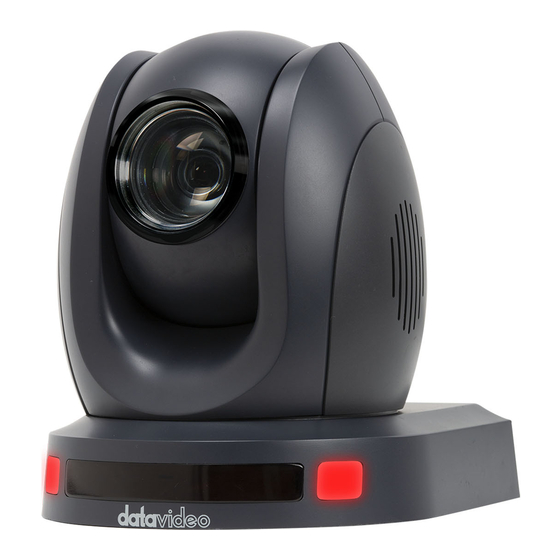
Page 10: Location And Function Of Parts
3. Location and Function of Parts Front of Camera Lens Built-in 1/2.8” 2.07M Pixel CMOS HD color camera with white balance control, backlight compensation settings, automatic gain settings and etc. Tally LED Tally lamp lights up when tally signal has been transmitted to the tally signal box. - Page 11 Rear of Camera Power Input DC in socket connects the supplied 12V PSU. The connection can be secured by screwing the outer fastening ring of the DC In plug to the socket. LAN Port This port is used to output the video of the camera. Please connect a Ethernet cable from this port to the LAN port of a PC or Notebook PC and then users can monitor the video of the camera from the web control interface.
- Page 12 Bottom of Camera Tripod Screw Hole allows the user to mount the camera on the tripod. Screw Hole Screw holes for ceiling bracket mounting. Safety Rope Loop Safety rope loop for fixing the camera.
-
Page 13: Connections
4. Connections 4.1 Camera Rear Control Panel HDBaseT Port for connection to the PTC-140T Receiver Box HDBaseT port using a CAT5e/6 cable. 4.2 Receiver Box Front Panel... - Page 14 HDBaseT Port for connection to the PTC-140T Camera HDBaseT Port using a CAT5e/6 Cable RS-232/RS-422 Interface (Phoenix Terminal) Connects to external RS-232/RS-422 device. RX: Receiver PIN (differential pair if using RS-422 connection) TX: Transmitter PIN (differential pair if using RS-422...
-
Page 15: Receiver Box Rear Panel
Connect the DVIP port to an Ethernet switch or router, serving as a communication port between the network and the HBT-11 receiver. Note: The HBT-11 is not the accessory of the PTC-140T, The HBT-11 will be packaged only with the PTC-140TH. -
Page 16: How To Connect The Ptc-140T Camera To The Hs-1600T Hdb Aset Portable
The Factory Default Baud rate for the HS-1600T is 38400 and this value can not be changed by users. The Factory Default Baud rate for the PTC-140T is set at 38400 and there is no need for users to change it. However, if there is something wrong when connecting the PTC-140T with the HS-1600T, please check whether the Baud rate of the PTC-140T is changed or not. -
Page 17: How To Set Ptc-140T's Video Format To Be Consistent To Hs-1600T's Pgm Out Resolution
Step 5. Please press the “Left” key or “Right” key to set the Baud rate at 38400. Please make sure that the Baud rate of the PTC-140T and the Baud rate of the HS-1600T must be consistent to assure their normal operation. - Page 18 Step 12. Please select the “Yes” button by using the “Left or Right Arrow” key and then please press the “Enter” button on the keyboard of the HS-1600T to save the updated settings. The system diagram for the PTC-140T and the HS-1600T connection is shown as following diagram.
-
Page 19: System Diagram For The Ptc-140T And The Hs-1600T Connection
4.4.2 System Diagram for the PTC-140T and the HS-1600T Connection... -
Page 20: Basic Setup
140T camera to the HDBaseT port on the front panel of the HDBaseT receiver box. Step 2. Please connect a HDMI cable from the HDMI OUT port to the HDMI port of the external connected monitor. Step3. After the self-test of the PTC-140T camera is done, the video will be shown. -
Page 21: Remote Control And On-Screen Menu
6. Remote Control and On-Screen Menu 6.1 Remote Control Functions Item Description Standby button After pressing the Standby button for 3 seconds, the camera will do the self-test again and then go back to the Home position. (Note: If power-on mode is turned on and Preset 0 is set, and there is no operation within 12s, it will automatically... - Page 22 The * and # keys are used for key combination. The PTC-140T provides 17 key combinations for users which are shown as *, # Keys follows. (1) 【#】+【#】+【#】: Clear all presets. (2) 【*】+【#】+【6】: Restore factory defaults (3) 【*】+【#】+【9】: Switch images between normal & Up- side down position.
- Page 23 13. Home Key Users can press the Home Key to change the camera head of the PTC-140T back to the center position. Users can also press the Home key to enter next level of the OSD MENU once the OSD MENU is shown.
- Page 24 Set the camera address as No.3: Please press 【*】+【#】+ 【F3】from the remote controller. Set the camera address as No.4: Please press 【*】+【#】+ 【F4】from the remote controller. Note: If users press the *+#+MANUAL buttons, the IP address of the PTC-140T will be resumed to factory default 192.168.5.163...
-
Page 25: On-Screen Menu (Control By Remote Controller)
6.2 On-Screen Menu (Control by Remote Controller) On-Screen Menu allows the user to change various camera settings such as shooting conditions and the system setup. The PTC-140T provides several options in the first layer OSD MENU including Language, (Setup), (Camera), (P/T/Z), (Video Format), (Version) and (Restore Default). - Page 26 Restore Default Restore Default...
- Page 27 Details of all options in the on-screen menu are listed in the table below. First Level Second Level Third Level Fourth Level Sub-Option Main Options Sub-Options Parameters Parameters Descriptions 1. Language (English/Simpli fied Chinese) 1. Auto 2. VISCA Protocol 3. PELCOO-D 4.
- Page 28 Gain Limit 0~15 Closed Auto 3000K 3500K 4000K 4500K 5000K WB Mode 5500K 6000K 6500K 7000K Manual Onepush RG Tuning Color BG Tuning...
- Page 29 100% 110% 120% Saturation 130% 140% 150% 160% 170% 180% 190% 200% High AWB Sensitivity Middle Brightness Image Contrast...
- Page 30 Sharpness Flip-H Flip-V Color B & W Mode Black & White Default 0.45 Gamma 0.50 0.55 0.63 DZoom Closed Auto Focus Mode Manual Onepush Focus AF-Zone Center Bottom...
- Page 31 High AF-Sensitivity Middle Auto NR-2D Noise Reduction NR-3D Dynamic Hot Pixel Default Normal Style Clarity Bright Soft Zoom by Speed Zoom Speed 4. P/T/Z Image Freezing Slow Acc Curve Fast 1080P60 1080P50 1080I60 1080I50 5. Video 1080P30 Format 1080P25 720P60 720P50 1080P59.94...
- Page 32 1080I59.94 1080P29.97 720P59.94 6. Network DHCP Settings IP Addr 192.168.x.x MCU Version Camera Version 7. Version AF version 8. Restore Restore Default Default (Yes/No)
-
Page 33: Professional Jargon Explanations Of The Osd Menu
6.3 Professional Jargon Explanations of the OSD Menu There are some professional jargons or nouns which are shown in the OSD menu of the PTC-140T camera, please refer to this section for realizing those jargons. Speed by Zoom: When this function is turned “ON”, at the time when... -
Page 34: Installation Instructions
4, PA4 plastic screw stopper x 4, PM3x5 screw x 6, ceiling upper covering plate x 1, ceiling lower covering plate x 1 and PTC-140T camera x 1 are needed. Step 1. The Ceiling Bracket, Ceiling Upper Cover Plate and Ceiling Lower Covering Plate ... - Page 35 Step 2. Mount the Ceiling Upper Covering Plate to the Ceiling At first, Please screw 4 PA4 plastic screw stoppers into the ceiling as shown as following diagram. Please connect the ceiling upper covering plate to the screw stoppers by using 4 PA4*30 self-tapping screws.
- Page 36 Step 3. Mount the PTC-140T Camera to the Ceiling Lower Covering Plate Please screw the PTC-140T camera to the ceiling lower covering plate by using 3 PM3*5 screws as shown as following diagram.
- Page 37 Step 4. Mount the PTC-140T Camera with the Ceiling Lower Covering Plate to the Ceiling Upper Covering Plate on the Wall Please push the PTC-140T camera with the ceiling lower covering plate according to the direction of following diagram and then please hook the ceiling lower covering plate to the ceiling upper covering plate.
-
Page 38: Direct Connection To Camera
8. Direct Connection to Camera To use the PTZ Camera Control Unit to directly control the PTC-140T camera, connect the Mini-Din 8 pin RS-232 port on the camera’s rear panel to the DB9 pin RS-232 port on the control keyboard or PC by a Mini-Din 8 pin to DB9 pin adapter cable. -
Page 39: Mini-Din 8 Pin Definition
8.1 RS-232 Mini-Din 8 Pin Definition Port Definition Data Terminal Ready Data Set Ready Transmit Data System Ground Receive Data System Ground IR OUT IR Commander Signal No Connection 8.2 RS232 (DB9) Pin Definition Port Definition Data Carrier Detect Receive Data Transmit Data Data Terminal Ready System Ground... -
Page 40: Ptc-140T's Web-Based User Interface
Step 6. Please connect an RJ-45 Ethernet cable from the LAN interface on the rear panel of the PTC-140T to the RJ-45 Ethernet port of a router. Step 7. You can see the IP address and the IR address of the PTC-140T-T will be shown on the top-left side of the screen. - Page 41 Step 8. Please connect an RJ-45 Ethernet cable from the RJ-45 port of your PC to the LAN port of the router. Step 9. The default IP mode for the PTC-140T is Static IP mode. So please set your PC in Static IP mode in advance. Since the Static IP address of the PTC- 140T is 192.168.5.163, the IP address for your PC must be set in 192.168.5.x...
- Page 42 Step 11. Please enter the default User Name and Password and then click the Login button. The Default User Name: admin The Default Password: admin Step 12. Please click the “Configuration” option of the web UI and then click the “Ethernet” option. After that, please check the “DHCP” checkbox and then click the “Save”...
- Page 43 Step 13. Please click the “Reboot” button from the Reboot option to reboot the camera. Step 14. Please set the network setting of your PC in DHCP mode.
-
Page 44: Connect The Camera To The Pc In Static Ip Mode
Step 6. Please connect an RJ-45 Ethernet cable from the LAN interface on the rear panel of the PTC-140T to the RJ-45 Ethernet port of a router. Step 7. You can see the IP address and the IR address of the PTC-140T-T will be shown on the top-left side of the screen. - Page 45 Step 9. The default IP mode for the PTC-140T is Static IP mode. So please set your PC in Static IP mode. Since the Static IP address of the PTC-140T is 192.168.5.163, the IP address for your PC must be set in 192.168.5.x Step 10.
- Page 46 Step 12. After logging into the PTC-140T web UI, the main interface of the web UI will be shown.
-
Page 47: Dvip
DNS. Depending on your operating system, download DVIP Configuration Tool from the respective sites listed as follows: https://www.microsoft.com/en-us/p/dvip-network- config/9p6gtz839k6s?activetab=pivot%3Aoverviewtab Android: https://play.google.com/store/apps/details?id=com.datavideo.dvipnetconfig &hl=en_US iOS: https://itunes.apple.com/tw/app/dvip-network- config/id1177895983?mt=8 After you’ve installed the DVIP Network Configuration Tool, follow the steps outlined below to scan for online DVIP devices and configure their... - Page 48 Step 1: Open the DVIP Network Configuration Tool and then select the connected Ethernet option from the “Network interface” pop-up window. After that please press the “OK” button. Step 2: After the Network interface is selected, the DVIP Network Configuration Tool interface will be shown as following diagram.
- Page 49 Step 3: Please press “HOST NAME” and then the network settings pop-up window will be shown.
- Page 50 Step 4: Users can click “Host Name” column for changing the device name. Users can also click each setting column for changing value if it is needed. After that, please press “Save” for saving those settings. Users can also press “Default”...
-
Page 51: Introduction Of The Ptc-140T Web User Interface
9.3 Introduction of the PTC-140T Web User Interface The web based user interface of the PTC-140T provides users three main options for setting and controlling the PTC-140T through the web UI. The web user interface of the PTC-140T provides users three main options including Preview, Configuration and Logout. - Page 52 Profile of the image is HP or the image is compressed in H.265 format, this image can not be shown in the Preview window. If the H.264 format is selected, the preview screen can be shown normally which is shown as following diagram. ...
-
Page 53: Control Functions
Control Functions Further to the right, there are various control functions, such as PTZ control, PTZ speed slider, focus mode drop-down menu, zoom and focus controls, as well as presets for saving PTZ settings. Details of each will be described in the table below. -
Page 54: Preset
Controls Descriptions Zoom IN/OUT Click to zoom in and zoom out. Preset The presets allow you to save multiple PTZ settings to the camera. See function descriptions in the table below. Functions Descriptions Preset Drop-Down Menu Select a preset number from the drop-down menu. -
Page 55: The Operations Of Zoom And Focus Buttons In Different Focus Modes
9.3.1.2 How to Set the Preset Positon Please follow following steps for setting your desired preset. Step 1. Please adjust the pan and tilt of the PTC-140T camera to your desired position. Step 2. Please make sure that other parameters including Zoom, Focus and those parameters in the Configuration option are set in advance. -
Page 56: How To Change The Ptz Speed Of The Camera
The default number of the PTZ speed control slider is 50 and the range for adjusting is from 0 to 100. Please follow following steps for adjusting the PTZ speed of the PTC-140T camera. Step 1. Please slide the PTZ speed control slider to the left side to reduce the pan and tile speed of the camera lens according to the number. -
Page 57: Audio Configure
9.3.2.1 Audio Configure The Audio Configure option allows users to set audio related parameters for the input audio source. The main interface of the Audio Configure option is shown as following diagram. Please see following table for the introduction of Audio Configure. Enable This Enable check box allows users to enable the settings for the... - Page 58 Encode Type This drop-down menu allows users to select their desired Encode type for the input audio source. There are three Encode type for users to select including MP3, AAC and G.711A. Sample Rate This drop-down menu allows users to select their desired sample rate for the input audio source.
-
Page 59: Video Configure-Video Encode
9.3.2.2 Video Configure-Video Encode The Video Encode option allows users to set many Video Encoder related parameters for the main stream and sub stream including Compressed Format, Profile, Image Size, Rate Control, Image Quality, Bit Rate(kb/s), Frame Rate(F/S), I Frame Interval, I Frame Min QP and Stream Name. The main interface of the Video Encode in the Video Configure option is shown as following diagram. - Page 60 Image Size Select an appropriate image size from the drop-down menu. 1920 x 1080 1280 x 720 640 x 480 Rate Control CBR encoding does not optimize media files for quality but will save you storage space. VBR takes longer to encode but produces the most favorable results as the quality of the media file is superior.
- Page 61 I Frame Interval A shorter I Frame Interval results higher quality video but consumes more network bandwidth. On the other hand if longer I Frame Interval is set, less bandwidth will be required but it will result in lower video quality. I frame interval is 75 by default.
-
Page 62: Video Configure-Stream Publish
9.3.2.3 Video Configure-Stream Publish In Stream Publish, you will be able to configure the RTSP, RTMP or SRT settings for main and sub streams. See the diagram below for various RTSP, RTMP or SRT settings. See the table below for descriptions of each item. Items Descriptions Enable... - Page 63 Items Descriptions Host Port The host port number is 1935 by default. Stream Name This is the RTMP/RTSP Stream Name/Key provided by the video streaming providers. An example of the RTMP Stream Name/Key is provided. User Name / Password Enter the login credentials of your live streaming platform or the Source Username &...
-
Page 64: How To Stream The Ptc-140T Video To The Rtmp Platform
(Take Youtube as an Example) Please follow following steps for streaming PTC-140T video to the RTMP platform. Step 1. Please make sure the PTC-140T and other devices are successfully connected. Step 2. Please obtain the stream server address and the stream token from the Youtube platform. -
Page 65: How To Stream The Ptc-140T Video To The Rtmp Platform
Step 6. Please check the Enable checkbox for the main stream/sub stream. Step 7. Please press the save button and then the streaming can be done successfully through the Youtube platform. 9.3.2.3.2 How to Stream the PTC-140T Video to the RTMP Platform (Take Facebook as an Example) ... - Page 66 140T’s web UI respectively. Please modify the “Host Port” to 443. 3. Check the Enable checkbox to enable RTMP stream. 4. Click the Save button to save the RTMP settings. 5. Please press the “Reboot” button from the Reboot option from the PTC-140T Web UI.
- Page 67 6. The preview screen will be shown on the bottom-right corner of the Facebook Live page. Please select where you want to post your live- streaming and who can see your live-straming. After that, please enter the title of the live-streaming and then please click “Go Live” button for live-streaming the video which is shot by the camera to the Facebook page.
- Page 68 Facebook Fan Page. Check “Use stream key” then copy and paste “Server URL” and Stream Key” into “Host Address” and “Stream Name” as shown on the PTC-140T’s web UI respectively. Please modify the “Host Port” to 443. 3. Check the Enable checkbox to enable RTMP stream.
- Page 69 7. After the live-streaming is started, users can see related information for the live-streaming video from the Facebook Live interface. If you want to stop the live-streaming, please click the “End Live Video” button for stopping your Facebook live-streaming.
- Page 70 Wowza Streaming Cloud is a cloud streaming platform which is a global leader in the live-streaming area. This chapter will take Wowza Streaming Cloud as an example to show how to do the RTSP streaming by Datavideo PTC-140T with the Wowza Streaming Cloud. Please see following steps to know how to stream the RTSP streaming by the PTC-140T camera to Wowza Streaming Cloud.
- Page 71 3. If you already have your own Wowza account, please enter your Email Address and Password and then click the “Sign In” button for logging into your own Wowza account which is shown as following diagram. If you do not have the Wowza account, you can apply a Wowza trial account for a 30 day free trial.
- Page 72 5. After logging into your account, users can see that there are two kinds of products including “Wowza Streaming Cloud” and “Wowza Streaming Engine”. What we need is the Wowza Streaming Cloud, so, please click the “FREE TRIAL” button of the “Wowza Streaming Cloud”.
- Page 73 6. Please click the “Launch Wowza Streaming Cloud” button for launching the Wowza Streaming Cloud. 7. You will see the main interface of the Wowza Streaming Cloud which is shown as following diagram. Please click “Add Live Stream” button for adding a new live-streaming.
- Page 74 8. Please enter your desired name for the stream into the “What is the name of your live stream?” column. For this example, the stream name is “RTSP Stream”. 9. Please click one of the following countries which is located at the nearest location to where you want to start the live-streaming.
- Page 75 10. Please select the camera or the encoder that you want to use to connect to Wowza Streaming Cloud. This example is RTSP streaming, so, please select “Other RTSP” option from the following diagram. You can keep other options as default values. After that, please click the “Next” button.
- Page 76 11. This page allows users to set some detailed settings. After all parameters are set, please click the “Next” button.
- Page 77 12. Please enter your desired title and then click the “Next” button. 13. This page allows you to check all parameters before starting the live- streaming. Please confirm that all parameters are correct and then click the “Finish” button. 14. Please do the streaming settings according to following steps. ...
- Page 78 Please copy the “Host Port” and then paste it into the “Host Port” column in the “Stream Publish” page of the PTC-140T Web UI. Please copy the “Stream Name” and then paste it into the “Stream Name” column in the “Stream Publish” page of the PTC-140T Web UI.
- Page 79 16. Please click the “Reboot” button from the “Reboot” option in the PTC- 140T Web UI. 17. Users can see the image which is shot by the PTC-140T is streamed to Wowza Streaming Cloud platform successfully by using the RTSP protocol.
- Page 80 How to do the SRT Streaming by the vMix Software How to install the Vmix Software Please install the vMix software according to following steps. 1. At first, please go to vMix official website and then download the vMix 60- day free-trial.
- Page 81 4. Please click “I accept the agreement” and then click the “Next” button. 5. Please click the “Next” button.
- Page 82 6. Please click the “Next” button. 7. Please click the “Next” button.
- Page 83 8. Please click the “Install” button. 9. The installation will be started.
- Page 84 10. Please click the “Finish” button to finish the installation. 11. Please select “Register for a fully functional 60 Day Trial” to fill out your Email Address. After that, please click the “OK” button to open the vMix software.
- Page 85 12. Please select the initial resolution and frame rate that you want to use and then please click the “OK” button. 13. After opening vMix, the software interface is shown as following diagram.
- Page 86 If the PTC-140T is set in Listener Mode Note: If vMix is set in Caller Mode, the PTC-140T Web UI must be set in Listener Mode. If vMix is set in Listener Mode, the PTC-140T Web UI must be set in Caller Mode.
- Page 87 2. Users can see the main interface of the vMix which is shown as following diagram. 3. Please go back to the interface of the PTC-140T Web UI, click the “SRT” option, and then select your desired SRT encryption way from “Crypto key length in bytes”.
- Page 88 4. Please click the “Reboot” button from the “Reboot” option for rebooting the PTC-140T. 5. Please go back to vMix and then please click “Add Input”. After that, please click “More” from the drop-up menu.
- Page 89 PTC-140T Web UI, which is “8888888888” in the “Passphrase” column. And then please select “32” in the “Key length” drop- down menu to make sure that it is consistent as the setting in the PTC-140T Web UI.
- Page 90 8. Users can see that the image which is shot by the PTC-140T is streamed to vMix software by the SRT Listener Mode.
- Page 91 If the PTC-140T is set in Caller Mode Note: If vMix is set in Caller Mode, the PTC-140T Web UI must be set in Listener Mode. If vMix is set in Listener Mode, the PTC-140T Web UI must be set in Caller Mode.
- Page 92 3. Please go back to the interface of the PTC-140T Web UI, click the “Stream Publish” option, and then you can see the “Stream Publish” interface which is shown as following diagram. 4. Please select “SRT” option from the “Protocol Type” drop-down menu.
- Page 93 “Passphrase” password to “88888888” which is consistent to the “Password for Stream Encryption” in the “Stream Publish” page of the PTC- 140T web UI. After that, please set the “Key length” drop-down menu to 32, which is consistent to the PTC-140T web UI.
- Page 94 13. Finally, please click the “OK” button. 14. Users can see that the image which is shot by the PTC-140T is streamed to vMix software by the SRT Caller Mode.
-
Page 95: Rtp Multicast
9.3.2.4 RTP Multicast The RTP Multicast allows you to view camera video on certain video players such as VLC media player from a remote location. Follow the steps outlined below to view the camera video on VLC media player. 1. Download VLC media player from the link https://www.videolan.org. 2. - Page 96 You can also choose to stream over TS protocol. Follow the steps outlined below to view the camera video on VLC media player over TS protocol. 1. On RTP Multicast page of the PTC-140T’s web interface, select “TS” from the Protocol Type drop-down menu.
-
Page 97: Video Parameters
3. Click the “Play” button to start viewing the video stream. 9.3.2.5 Video Parameters This sets the camera focus, exposure, color balance, image settings, noise reduction and picture styles. Focus In Focus, you are allowed to set Focus Mode, Auto Focus Zone and Auto Focus Sensitivity. - Page 98 AF-Sensitivity: This sets auto focus sensitivity by selecting High, Middle and Low from the drop-down menu. Exposure In Exposure, you are allowed to set Exposure Mode, Exposure Value (EV), Backlight Compensation (BLC), Anti-Flicker, Gain Limit and Dynamic Range Compression (DRC). ...
- Page 99 Shutter Automatic Exposure – The camera will measure light and automatically set the aperture based on your desired shutter speed. Aperture Automatic Exposure – The camera will measure light and automatically set the shutter speed based on your desired iris opening (aperture).
- Page 100 WB Mode: Select white balance mode from the options listed below. Auto Manual One Push 2400K 2500K 2600K 2700K 2800K 2900K 3000K 3100K...
- Page 101 3200K 3300K 3400K 3500K 3600K 3700K 3800K 3900K 4000K 4100K 4200K 4300K 4400K 4500K 4600K 4700K 4800K 4900K 5000K 5100K 5200K 5300K 5400K 5500K 5600K 5700K 5800K 5900K 6000K 6100K 6200K 6300K 6400K 6500K 6600K 6700K 6800K...
- Page 102 6900K 7000K 7100K RG Tuning: This fine tunes the red gain from -10 to 10 but effective only in AUTO mode. BG Tuning: This fine tunes the blue gain from -10 to 10 but effective only in AUTO mode. ...
- Page 103 Bright: Brightness level adjustment from 0 to 14. Contrast: Contrast adjustment from 0 to 14. Sharpness: Sharpness adjustment from 0 to 15. Gamma: Selects a gamma value from the following Default 0.45 0.50 0.55 0.63...
- Page 104 DCI: To enable DCI, simply select a value from 1 to 8; selecting OFF will disable DCI. B&W Mode: This allows you to switch between color and black-and-white modes. Flip-H: Turning it ON flips the image along the horizontal axis. ...
- Page 105 NR-2D: 2D noise reduction is ideal for scenes with movement. 1 – 7 Auto NR-3D: 3D noise reduction is ideal for static fields of view. 1 – 7 Note: By using both 2D and 3D noise reduction together, you can effectively enhance both moving and static imagery, which is ideal for most live broadcast environments.
- Page 106 Note: Each time after you modify the camera parameters, please click the Refresh button to apply the new settings.
-
Page 107: Video Osd
9.3.2.6 Video OSD In Video OSD, you will be allowed to show video time and title on the screen. You can further set the font color as well as their positions. Enable Video Time and Title on Screen Simply check the checkbox then click the Save button to display video time and title on the screen. - Page 108 White Black Yellow Blue Adjust Time and Title Positions On the OSD Offset tile, you will be allowed to adjust positions of the Time and Title displayed on the screen. First select Time or Title then click the arrow buttons to move it to the desired position.
-
Page 109: Osd Font Size
9.3.2.7 OSD Font Size In OSD Font Size, you can set the font size for the Master and Slave streams by entering a number into the respective textboxes shown in the diagram below. In addition, you can also select to allow the system to scale the font size automatically according to the resolution set. -
Page 110: Network Configure
1080P29.97 Note: Click the Save button after you’ve selected a resolution. 9.3.2.9 Network Configure Network Configure allows you to configure the network functions of your camera. -
Page 111: Network Port
9.3.2.9.1 Network Port In Network Port, you should be able to find a list of default port numbers for different data communication protocols. Please note that these port numbers may vary according to your network environment. Note: Click the Save button after you’ve edited the port numbers. -
Page 112: Ethernet
9.3.2.9.2 Ethernet In Ethernet, you are allowed to modify your network settings according to your network environment. For more details on DHCP and Static IP Mode, see Network Connection. Note: Click the Save button after you’ve edited the network settings. -
Page 113: Dns
9.3.2.9.3 DNS In DNS, Enter the DNS information which is 8.8.8.8 by default. 9.3.2.9.4 SRT The main interface of the SRT option is shown as following diagram. This interface provides the SRT port No. The default port No. is 9000. Moreover, if users want to encrypt the SRT stream, it allows users to set their desired SRT password and the SRT crypto key length. -
Page 114: System Configure
9.3.2.10 System Configure System Configure allows you to configure your camera system. 9.3.2.10.1 System Attribute In System Attribute, you are allowed to edit your camera name and select the Web UI language. Available languages are Traditional Chinese, Simplified Chinese and English. -
Page 115: System Time
9.3.2.10.2 System Time In System Time, you are allowed to set the Date Format, Time Zone, Hour Type and NTP. NTP stands for Network Time Protocol and it is an Internet protocol used to synchronize the clocks of devices over a network to some time reference. Once NTP is enabled, you will be allowed to select the update frequency and assign the time server. -
Page 116: System User
9.3.2.10.3 System User In System User, you are allowed to edit the login credentials for Admin, User 1 and User 2. Note: Click the Save button to save the new login credentials. 9.3.2.10.4 Update This is where you will be able to view current firmware information. See Firmware Update for detailed firmware upgrade instructions. -
Page 117: Default
9.3.2.10.5 Default In Default, click “Restore factory defaults” to reset the device to factory defaults. -
Page 118: Reboot
9.3.2.10.6 Reboot Click “Reboot” to reboot the device. -
Page 119: Firmware Update
How to Update the Latest Firmware for the PTC-140T Camera Please follow following steps for updating the latest firmware for the PTC- 140T camera. Step 1. Please download the latest firmware of the camera from Datavideo Official website https://www.datavideo.com/product/PTC-140T Step 2. Please download the latest firmware and then save the firmware in the hard disk of your PC. -
Page 120: Frequently-Asked Questions
11. Frequently-Asked Questions This section describes problems that you may encounter while using the PTC- 140T. If you have questions, please refer to related sections and follow all the suggested solutions. If problem still exists, please contact your distributor or the service center. - Page 121 Sometimes 1. Please check whether the cable connection there is no between the camera and the external connected image? monitor is connected correctly. Image jittering 1. Please check whether the camera is well-mounted. is happened 2. Whether there is a vibrating machine or object that when the is around the camera.
- Page 122 The camera 1. Please check whether the control cable is the standard control cable that is provided by our can not be company. controlled by the serial port. 2. Please check whether the protocol, baud rate and address of the device that is connected are consistent to the protocol, baud rate and address of the camera.
- Page 123 UI again, the delay time will be resumed to less than 0.5 seconds. Important When the PTC-140T is set in SRT Caller Mode, the vMix must be set in SRT Listener Mode. When the PTC-140T is set in notice when...
-
Page 124: Dimensions
12. Dimensions Unit: mm... -
Page 126: Specifications
13. Specifications Camera Parameters 1080p 60/59.94/50/30/29.97/25 Video Format 1080i 60/59.94/50 720p 60/59.94/50 Image Sensor 1/2.8 inch high quality HD CMOS sensor Effective Pixels 2.07 Mega pixels (approx.) S/N Ratio >55dB Min. Illumination 0.5Lux (F1.8, AGC ON) Electronic Shutter Auto / Manual Zoom Ratio 20x Optical Zoom, 10x Digital Zoom Gamma Control... - Page 127 Image Compensation Backlight Compensation Input /Output Interfaces HDBaseT (PoE) x1 Video Output RJ-45 x1 Audio Input 3.5mm Line in Tally LED Dual colors (Red, Green) Lens Filter M52.0 x 0.75 Thread with UV Protection VISCA/Pelco-D/Pelco-P; Baud Control Protocol Rate:115200/38400/9600/4800/2400bps DVIP RS-232 Remote Control Lan (RJ-45)
- Page 128 Tripod Mount 1/4-20 UNC Optional Accessories WM-1/ WM-10 Color Dark Blue/White Dimension (LxWxH) 156 x 184 x 186 mm Weight 1.6 kg Operating Temp. 0~40 °C Range Power DC 12V 12W...
-
Page 129: Cable Selection
Cable Selection Video Resolutions (HDBaseT Connection) Cable Range Video Resolution Up to 1080p, 60Hz, 36 bpp. 100 meters Data rates lower than 5.3 Gbps or below 255 MHz CAT5e/6 TMDS clock. 70 meters Ultra HD video formats: HDMI Deep color: 1080p, 60, 48 bpp. 4K x 2K CAT6a/CAT7 100 meters(*) - Page 130 Note...
- Page 131 Note...
-
Page 132: Service & Support
Datavideo Technologies Co., Ltd. All rights reserved 2020 Apr..-07.2021 Ver:E7...