
Related Manuals for Amprobe AM-530


Summary of Contents for Amprobe AM-530
- Page 1 AM-520 HVAC Multimeter AM-530 True-rms Electrical Contractor Multimeter AM-520-EUR AM-530-EUR Digital Multimeter Users Manual...
-
Page 3: Digital Multimeter
AM-520 HVAC Multimeter AM-530 True-rms Electrical Contractor Multimeter AM-520-EUR / AM-530-EUR Digital Multimeter Users Manual 11/2012, Rev.2 ©2012 Amprobe Test Tools. All rights reserved. Printed in China... - Page 4 Amprobe® distributor for an exchange for the same or like product. Please check the “Where to Buy” section on www.amprobe. com for a list of distributors near you. Additionally, in the United States and Canada In-Warranty repair and replacement units can also be sent to a Amprobe®...
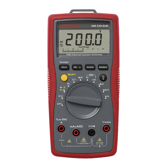
- Page 5 AM-520 HVAC Multimeter AM-530 True-rms Electrical Contractor Multimeter AM-520-EUR / AM-530-EUR Digital Multimeter Flash light Flash light Button LCD Display Rotary Switch Function Buttons SELECT Button Input Terminal for voltage, diode, capacitance, Resistance, continuity and temperature measurement COM (return) terminal for all measurements...
- Page 6 Screen Display 13 14 15 The Meter selects the range with best resolution Direct Current Negative reading Alternate Current Low battery indicator Data hold Diode test Continuity test Relative zero mode Non-Contact Voltage Measurement units for Resistance Measurement units for Frequency Measurement units for Voltage Measurement units for Current Measurement units for Capacitance...
-
Page 7: Table Of Contents
AM-520 HVAC Multimeter AM-530 True-rms Electrical Contractor Multimeter AM-520-EUR / AM-530-EUR Digital Multimeter CONTENTS SYMBOL .........................2 SAFETY INFORMATION ..................2 UNPACKING AND INSPECTION ................3 FEATURES .......................4 MAKING MEASUREMENT ..................5 Measuring AC and DC Voltage .................6 Measuring AC and DC Current .................7 Measuring Resistance ..................8... -
Page 8: Symbol
SYMBOLS Caution ! Risk of electric shock. � Caution! Refer to the explanation in this Manual Alternating Current (AC) Direct Current (DC) The equipment is protected by double insulation or reinforced insulation Earth (Ground) Audible tone Battery � Complies with European Directives �... -
Page 9: Unpacking And Inspection
• Remove test leads from the Meter before opening the Meter case or battery door. UNPACKING AND INSPECTION Your shipping carton should include: AM-520 or AM-530 or AM-520-EUR or AM-530-EUR Pair of test leads Temperature probe Velcro strap 9V (6F22) battery (installed) -
Page 10: Features
“third hand” probe holder and VoltTect non-contact voltage detection. Safety rated to CAT III 600V. AM-530 / AM-530-EUR is the fully-featured multimeter of choice for the professional electrical contractor. Measure and verify presence of voltage in... -
Page 11: Making Measurement
MAKING MEASUREMENT X� 1. Use the proper function and range for measurements. 2. To avoid possible electrical shock, personal injury or damages to the Meter, disconnect circuit power and discharge all high-voltage capacitors before testing resistance and diode. 3. Connecting test leads: •... -
Page 12: Measuring Ac And Dc Voltage
Relative zero mode Manual or Auto range switching. The default setting is Auto ranging, press to switch to manual ranging RANGE (selectable resolutions). Press for 2 sec to return to auto ranging. MAX/MIN Maximum / minimum reading memory. Flash light Press to enable the function when at relevant rotary switch function. -
Page 13: Measuring Ac And Dc Current
Measuring AC and DC Current Press SELECT button to select AC or DC current measurement function. X� To avoid personal injury or damage to the Meter: 1. Do not attempt to make an in-circuit current measurement when the open-circuit potential to earth ground exceeding AC 600V or DC 600V 2. -
Page 14: Measuring Resistance
Measuring Resistance X� Disconnect circuit power and discharge all high-voltage capacitors before testing resistance. Note: On a higher resistance measurement (>1Me), the measurement may take a few seconds to get stable reading. Over range or open circuit indication: OL... -
Page 15: Measuring Continuity
Measuring Continuity X� Disconnect circuit power and discharge all high-voltage capacitors before testing continuity. Measuring Diode X� Disconnect circuit power and discharge all high-voltage capacitors before testing diode. -
Page 16: Measuring Capacitance
Measuring Capacitance X� Disconnect circuit power and discharge all high-voltage capacitors before testing capacitance. Measuring Frequency X� To avoid personal injury or damage to the Meter, do not apply voltage higher than 600V. -
Page 17: Measuring Temperature °C /°F
Measuring Temperature °C / °F X� 1. To avoid personal injury or damage to the Meter, do not apply thetemperature probe to any live conductive parts. 2. Temperature sensor K type (nickel-chromium/nichrosi) thermocouple is suitable for temperature measurement below 230°C (446°F). Measurement steps: Step 1: Turn the rotary switch to °C or °F position. -
Page 18: Non-Contact Voltage Sensing
Non-Contact Voltage Sensing 1. To avoid personal injury or damage to the Meter, do not test on un- insulated high voltage wires. 2. Buzzer will sound and screen will display “OL” when sensing AC voltage between 90V and 600V 3. Do not test on hazardous live wires higher than AC 600V 4. -
Page 19: Specification
SPECIFICATION Ambient temperature: 73.4°F ±9 (23°C ±5°C); Relative temperature: ≤75% Accuracy: ±(% of reading + digits) Maximum voltage between input terminal and earth ground: AC 600Vrms or DC 600V � Fuse for mA µA input: F1 fuse, 0.5A H 1000V fast-fuse, (6.3×32)mm �... - Page 20 600V ±(1.2%+3LSD) Note: Manual range only for 400.0mV range. Input impedance: Around 10MΩ Frequency response: 45Hz ~ 400Hz AM-520 / AM-520-EUR : Average sensing, rms indication. AM-530 / AM-530-EUR: True RMS. Overload protection: 600Vrms 3. Resistance Measurement Range Resolution Accuracy 400.0Ω...
- Page 21 Display range is 0V to 2.0V. Normal voltage is around 0.5V to 0.8V for silicon PN junction. Overload protection: 600V 5. Capacitance Measurement Range Resolution Accuracy 40.00nF 10pF ±(3%+10LSD) under REL status 400.0nF 100pF ±(3%+5LSD) under REL status 4.000μF 40.00μF 10nF ±(3%+5LSD) 400.0μF...
-
Page 22: Temperature Measurement
10mA Frequency response: 45Hz ~ 400Hz AM-520 / AM-520-EUR : Average sensing, rms indication. AM-530 / AM-530-EUR: True RMS. Overload protection: mA /µA range:F1 fuse, 0.5A H 1000V fast-fuse, ( 6.3×32)mm 10 A range:F2 fuse, 11A H 1000V fast-fuse, ( 10×38)mm 9. -
Page 23: Maintenance
MAINTENANCE AND REPAIR If the Meter fails to operate, check battery, test leads, etc., and replace as necessary. Double check the followings: 1. Replace the fuse or battery if the meter does not work. 2. Review the operating instructions for possible mistakes in operating procedure. - Page 24 Except for the replacement of the battery, repair of the meter should be performed only by a Factory Authorized Service Center or by other qualified instrument service personnel. The front panel and case can be cleaned with a mild solution of detergent and water.
- Page 27 Visit www.Amprobe.com for • Catalog • Application notes • Product specifications • User manuals Amprobe ® www.Amprobe.com info@amprobe.com Everett, WA 98203 Tel: 877-AMPROBE (267-7623) Amprobe® Europe Beha-Amprobe In den Engematten 14 79286 Glottertal, Germany Please Tel.: +49 (0) 7684 8009 - 0 Recycle...