Table of Contents
Advertisement
Quick Links
Download this manual
See also:
User Manual
Advertisement
Table of Contents

Related Manuals for Amprobe AM-540


Summary of Contents for Amprobe AM-540
- Page 1 AM-540 Advanced HVAC Multimeter AM-550 Industrial Multimeter AM-540-EUR AM-550-EUR Digital Multimeter Users Manual 99 Washington Street Melrose, MA 02176 Phone 781-665-1400 Toll Free 1-800-517-8431 Visit us at www.TestEquipmentDepot.com...
-
Page 3: Digital Multimeter
AM-540 Advanced HVAC Multimeter AM-550 Industrial Multimeter AM-540-EUR AM-550-EUR Digital Multimeter Users Manual August 2011, Rev.2 ©2012 Amprobe Test Tools. All rights reserved. Printed in China... - Page 4 Amprobe® Test Tools distributor for an exchange for the same or like product. Please check the “Where to Buy” section on www.amprobe. com for a list of distributors near you. Additionally, in the United States and Canada In-Warranty repair...
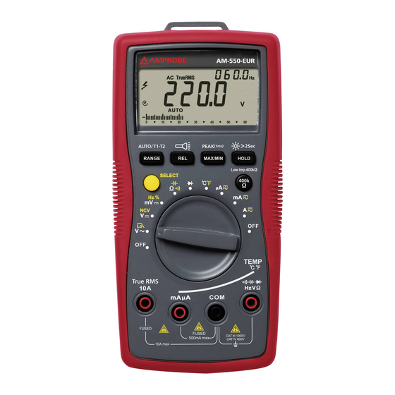
- Page 5 AM-540 Advanced HVAC Multimeter AM-550 I ndustrial Multimeter AM-540-EUR / AM-550-EUR Digital Multimeter Flash Light LCD Display Push Buttons (See Making Measurement for button functions) AM-550 / AM-550-EUR: Low Impedance button AM-540 / AM-540-EUR: Backlight button Rotary Switch SELECT Button...
-
Page 6: Table Of Contents
Screen Display 10 19 20 14 15 Auto range or Manual range Measurement units for Capacitance Direct current Duty cycle Negative reading Auto Power Off Alternate current Maximum / minimum reading memory True-rms value Positive peak / negative peak Low battery indicator reading memory Data hold Measurement unit for Temperature... - Page 7 AM-540 Advanced HVAC Multimeter AM-550 Industrial Multimeter AM-540-EUR / AM-550-EUR Digital Multimeter CONTENTS SYMBOL .........................2 SAFETY INFORMATION ..................2 UNPACKING AND INSPECTION ................3 FEATURES .......................4 MAKING MEASUREMENT ..................5 Rotary Switch Positions ..................6 Function Buttons ....................6 Measuring AC and DC Voltage ................9 Low Pass Filter ....................9...
-
Page 8: Direct Current
SYMBOLS Caution ! Risk of electric shock. � Caution! Refer to the explanation in this Manual Alternating Current (AC) Direct Current (DC) The equipment is protected by double insulation or reinforced insulation Earth (Ground) Audible tone Battery � Complies with European Directives �... -
Page 9: Unpacking And Inspection
• Do not use the Meter around explosive gas or vapor. • When using the test leads, keep your fingers behind the finger guards. UNPACKING AND INSPECTION Your shipping carton should include: AM-540 or AM-550 or AM-540-EUR or AM-550-EUR Multimeter Pair of test leads Temperature probe Temperature adaptor... -
Page 10: Data Hold
With built in flashlight, and non-contact voltage detection the AM-540 is the choice multimeter for a professional HVAC technician. Safety rated to CAT IV 600V, CAT III 1000V for the most advanced HVAC troubleshooting needs. -
Page 11: Temperature Measurement T1 Or T2
• Auto and manual ranging • Auto power off • Low battery warning • Velcro strap to hang a meter • Safety: CAT IV 600V, CAT III 1000V MAKING MEASUREMENT X� 1. Use the proper function and range for measurements. 2. -
Page 12: Function Buttons
AM-540 / AM-540-EUR Function Buttons Button Measurement Function Press the yellow SELECT button to select alternate SELECT measurement functions on the rotary switch. Manual or Auto range switching for voltage current, resistance and capacitance. The default setting is Auto ranging, press to switch to manual ranging. Press for 2 sec RANGE / to return to auto ranging. - Page 13 AM-550 / AM-550-EUR Function Buttons Button Measurement Function Press the yellow SELECT button to select alternate SELECT measurement functions on the rotary switch. Manual or Auto range switching for voltage current, resistance and capacitance. The default setting is Auto ranging, press to switch to manual ranging. Press for 2 sec RANGE / to return to auto ranging.
- Page 14 Dual Display AC voltage measurement Primary display shows AC voltage. Secondary display shows frequency. AC current measurement Primary display shows AC current. Secondary display shows frequency. Auto Power OFF Auto power off: approx. 15 minutes. When the Meter is in auto power off mode, press any button to resume normal operation.
-
Page 15: Measuring Ac And Dc Voltage
Measuring AC and DC Voltage X� To avoid personal injury or damage to the Meter, do not apply voltage higher than 1000Vac and 1000Vdc.Buzzer will sound when detect a voltage higher than 1000Vac and 1000Vdc. Low imp. 400Ω (For only) Low Pass Filter X�... -
Page 16: Measuring Frequency / Duty Cycle
Note: The Meter goes into manual mode when Low Pass Filter mode is enabled. Auto range mode is not available for Low Pass Filter option. Measuring Frequency / Duty Cycle X� To avoid personal injury or damage to the Meter, do not apply voltage higher than 1000V. - Page 17 (for Frequency only) 2. Measuring Frequency by using AC Voltage function Step 1: Turn the rotary switch to position. Step 2: Connect test leads to the circuit. Connect the common (COM) test lead to the circuit before connecting the live lead (connecting diagram refer to “Measuring AC Voltage”).
-
Page 18: Measuring Ac And Dc Current
3. Measuring Frequency by using AC Current function Step 1: Turn the rotary switch to μA or mA or 10A position. Step 2: Connect the test leads to the correct input 10A/mA μA current terminal and to the circuit before powering the circuit under test (connecting diagram refer to “Measuring AC Current”). -
Page 19: Measuring Resistance
Measuring Resistance X� Disconnect circuit power and discharge all high-voltage capacitors before testing resistance. Note: On a higher resistance measurement (>1Me), the measurement may take a few seconds to get stable reading. Over range or open circuit indication: OL... -
Page 20: Measuring Continuity
Measuring Continuity X� Disconnect circuit power and discharge all high-voltage capacitors before testing continuity. Press SELECT button for continuity function. Measuring Capacitance X� Disconnect circuit power and discharge all high-voltage capacitors before measuring capacitance. Use DC Voltage function to check the capacitors are discharged. -
Page 21: Measuring Diode
Measuring Diode X� DDisconnect circuit power and discharge all high-voltage capacitors before testing diode. Note: A typical junction voltage drops 0.5 V to 0.8 V. -
Page 22: Measuring Temperature °C / °F
Measuring Temperature °C / °F X� 1. To avoid personal injury or damage to the Meter, do not apply the temperature probe to any live conductive parts. 2. Temperature sensor K type (nickel-chromium/nichrosi) thermocouple is suitable for temperature measurement below 230°C (446°F). Measurement steps: Step 1: Turn the rotary switch to °C/°F position. -
Page 23: Non-Contact Voltage Sensing
Non-Contact Voltage Sensing X� 1. To avoid personal injury or damage to the Meter, do not test on un- insulated high voltage wires. 2. Buzzer will sound and screen will display “OL” when sensing AC voltage above 90V. 3. Do not test on hazardous live wires higher than AC 750V. 4. -
Page 24: Specification
SPECIFICATION Ambient temperature: 23°C ±5°C (73.4°F ±9°F); Relative temperature: ≤75% Accuracy: ±(% of reading + digits) Maximum voltage between input terminal and earth ground: AC 1000Vrms or DC 1000V � Fuse for mA µA input: F1 0.5A H 1000V fast-fuse, (Φ6×32)mm �... - Page 25 ±(1.2%+3LSD) ±(2.5%+3 LSD) Overload protection: 1000Vrms Input impedance: Around 10MΩ Frequency response: 45Hz– 400Hz (AM-540 / AM-540-EUR), 45Hz – 1kHz (AM- 550 / AM-550-EUR) AM-540 / AM-540-EUR: Average sensing, rms indication. AM-550 / AM-550-EUR: True RMS. Note: Frequency (on secondary display) may not be displayed if the measured voltage is below 20% of the display voltage range.
- Page 26 /µA range:F1 fuse, 0.5A H 1000V fast-fuse, ( 6×32)mm 10 A range:F2 fuse, 11A H 1000V fast-fuse, ( 10×38)mm 7. AC Current Measurement Accuracy 45Hz – 400Hz Range Resolution 400Hz – 1KHz (AM-540/ AM-550) (AM-550) (AM-540-EUR/ AM- 550-EUR) 600.0μA 0.1μA μA ±(1.2%+5 LSD) ±(2%+5 LSD)
- Page 27 µA mA range: F1 0.5A H 1000V fast-fuse, ( 6×32)mm 10 A range: F2 11A H 1000V fast-fuse, ( 10×38)mm Frequency response: 45Hz – 400Hz(AM-540 / AM-540-EUR), 45Hz – 1KHz (AM- 550 / AM-550-EUR) Note: Frequency (on secondary display) may not be displayed if the measured current is below 20% of the display current range.
-
Page 28: Temperature Measurement
600.0μF 100nF ±(4%+5 LSD) 6000μF 1μF ±(5%+5 LSD) 60mF 10μF Not specified Overload protection: 1000Vp 11. Temperature measurement Range Resolution Accuracy -40 – 40°C ±(2%+8 LSD) >40 – 400°C 1°C ±(1%+8 LSD) >400 – 1000°C ±2.5% -40 – 104°F ±(2%+12 LSD) >104 –... - Page 29 Continuity buzzer activates: the fuse is OK Continuity buzzer is not activated: the fuse is burnt. Replace the fuse as specified. F1 0.5A H 1000V fast-fuse, ( 6×32)mm Quick check on 10A FUSE: Step 1: Turn the rotary switch to A position.
-
Page 30: Battery And Fuse Replacement
BATTERY AND FUSE REPLACEMENT X� WARNING To avoid shock, injury, or damage to the Meter: Disconnect test leads before opening case. Use ONLY fuses with the amperage, interrupt, voltage, and speed ratings specified. Replacing BATTERY follow below steps: 1. Disconnect the test lead probe from measuring circuit. 2.