Table of Contents
Advertisement
Advertisement
Table of Contents

Related Manuals for D-Link DSL-2740E


Summary of Contents for D-Link DSL-2740E
- Page 1 DSL-2740E User Manual...
- Page 2 DSL-2740E User Manual FCC Statement This equipment has been tested and found to comply with the limits for a Class B digital device, pursuant to part 15 of the FCC rules. These limits are designed to provide reasonable protection against harmful interference in a residential installation.
- Page 3 DSL-2740E User Manual this device must accept any interference received, including interference that may cause undesired operation. Caution! Any changes or modifications not expressly approved by the party responsible for compliance could void the user's authority to operate the equipment.
- Page 4 DSL-2740E User Manual Users should ensure for their own protection that the electrical ground connections of the power utility, telephone lines and internal metallic water pipe system, if present, are connected together. This precaution may be particularly important in rural areas. Caution: Users should not attempt to make such connections themselves, but should contact the appropriate electric inspection authority, or electrician, as appropriate.
-
Page 5: Table Of Contents
DSL-2740E User Manual Contents Introduction ......................1 Safety Precautions ................1 LEDs and Interfaces ................2 System Requirements ................4 Features ....................4 Hardware Installation ..................6 ... - Page 6 DSL-2740E User Manual 3.4.6 Logout ..................98 Status ....................98 3.5.1 Device Info ................98 3.5.2 Wireless Clients ..............100 3.5.3 DHCP Clients ................101 3.5.4 ADSL Driver ................101 ...
-
Page 7: Introduction
DSL-2740E User Manual Introduction The DSL-2740E supports multiple line modes. With one 10/100 base-T Ethernet interfaces at the user end, the device provides high-speed ADSL broadband connection to the Internet or Intranet for high-end users like net bars and office users. -
Page 8: Leds And Interfaces
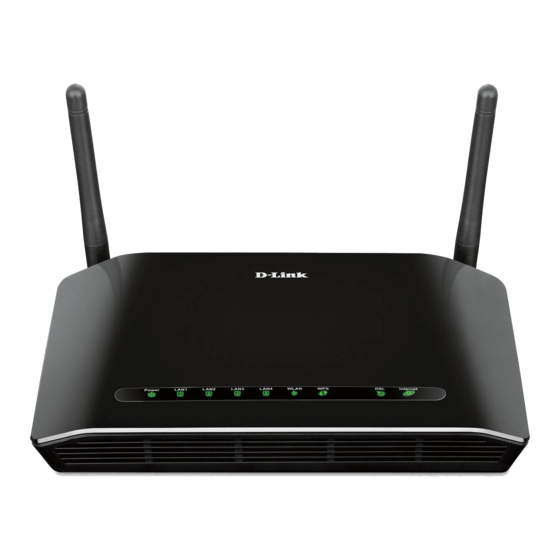
DSL-2740E User Manual 1.2 LEDs and Interfaces Note: The figures in this document are for reference only. Front Panel Figure 1 Front panel The following table describes the LEDs of the device. Color Status Description The initialization of the system Green is complete. - Page 9 DSL-2740E User Manual Color Status Description and the client, the LED would light steady for 5 seconds. Blinking WPS is successfully triggered. Device is ready for new WPS setup. No signal is being detected. The device is handshaking with Blinking...
-
Page 10: System Requirements
DSL-2740E User Manual For a PC or other Ethernet-abled device to join the LAN of LAN4/3/2/1 2740E by being connected to this interface with RJ-45 cable. Press and hold the button for 3 seconds start WPS negotiation. WIRELESS Press and hold the button for 2 seconds start WLAN. - Page 11 DSL-2740E User Manual 802.1Q and 802.1P protocol DHCP server NAT and NAPT Static route Firmware upgrade: Web, TFTP, FTP Reset to the factory defaults DNS relay Virtual server Two-level passwords and user names Web user interface Telnet CLI System status display...
-
Page 12: Hardware Installation
DSL-2740E User Manual Hardware Installation Step 1 Connect the DSL port of the device and the Modem port of the splitter with a telephone cable. Connect the phone to the Phone port of the splitter through a telephone cable. Connect the incoming line to the Line port of the splitter. -
Page 13: Web Configuration
This chapter describes how to configure the device by using the Web-based configuration utility. Note: This user manual is applied for DSL-2740U& DSL-2740E. 3.1 Accessing the Device The following is the detailed description of accessing the device for the first time. - Page 14 DSL-2740E User Manual If you log in as the super user successfully, the page shown in the following figure divided into two parts appears. This page displays a summary overview of the router, including the system information, DSL information, LAN Configuration, DNS information and WAN Configuration.
- Page 15 DSL-2740E User Manual Figure 5 Device information – 2...
-
Page 16: Setup
DSL-2740E User Manual 3.2 Setup In the main interface, click Setup tab to enter the Setup menu as shown in the following figure. The submenus are Wizard, Local Network, Internet Setup, Wireless Setup and Time and Date. 3.2.1 Wizard Wizard enables fast and accurate configuration of Internet connection and other important parameters. - Page 17 DSL-2740E User Manual There are 5 steps to configure the device. Click Next to continue. Step 1 Change the device login password. Step 2 Set the time and date.
- Page 18 DSL-2740E User Manual Step 3 Configure the Internet connection. If the internet service you subscribed is PPPoE or PPPoA, you can choose the Protocol to be PPPoE or PPPoA. Set the VPI and VCI. Enter the user name and password provided by your ISP.
- Page 19 DSL-2740E User Manual If the internet service you subscribed is Dynamic IP, you can choose Protocol to be Dynamic IP. The page shown in the following figure appears. If the Protocol is Static IP, you can choose Protocol to be Static IP. The page shown in the following figure appears.
- Page 20 DSL-2740E User Manual If the Protocol is Bridge, the page shown in the following figure appears.
- Page 21 DSL-2740E User Manual Step 4 Configure the wireless network. Step 5 Complete and apply the settings. Click Apply to save the settings.
-
Page 22: Local Network
DSL-2740E User Manual Note: In each step of the Wizard page, you can click Back to review or modify the previous settings. Click Cancel to exit the wizard page. 3.2.2 Local Network You can configure the LAN IP address according to the actual application. The preset IP address is 192.168.1.1. - Page 23 DSL-2740E User Manual 3.2.2.1 LAN Interface Choose Setup > Local Network > LAN Interface. The LAN Setting page shown in the following figure appears. You may configure the LAN interface, for example, the IP address and subnet mask.
- Page 24 DSL-2740E User Manual The following table describes the parameters in this page. Field Description Enter the IP address of LAN interface. It is recommended to use an address from a block reserved for private use. This Address address block is 192.168.1.1- 192.168.1.254.
- Page 25 DSL-2740E User Manual...
- Page 26 DSL-2740E User Manual The following table describes the parameters of this page. Field Description Specify the LAN global ipv6 address. It can be Global Address assigned by ISP. Enable Enable or disable the Router Advertisement feature. Enable or disable the “Managed address M Flag configuration”...
- Page 27 DSL-2740E User Manual The following table describes the parameters of this page. Field Description If set to DHCP Server, the router can assign IP addresses, IP default gateway and DNS servers to DHCP Mode the host in Windows95, Windows NT and other operation systems that support the DHCP client.
- Page 28 DSL-2740E User Manual Field Description retains the assigned IP addresses before the IP addresses change. Enter the domain name if you know. If you leave this blank, the domain name obtained by DHCP from the ISP is used. You must enter host name (system Domain Name name) on each individual PC.
- Page 29 DSL-2740E User Manual Description Field example, 00-A0-C5-00-02-12. It displays the lease time. The lease time determines Expiry the period that the host retains the assigned IP addresses before the IP addresses change. Refresh Click it to refresh this page. Click the button Set VendorClass IP Range to display the page Device IP Range Set.
- Page 30 DSL-2740E User Manual In the DHCP Mode field, choose DHCP Relay. The page shown in the following figure appears.
- Page 31 DSL-2740E User Manual The following table describes the parameters and buttons of this page: Field Description If set to DHCP Relay, the router acts a surrogate DHCP Mode DHCP Server and relays the DHCP requests and responses between the remote server and the client.
-
Page 32: Internet Setup
DSL-2740E User Manual Field Description Table. Select a row in the DHCP Static IP Table, then click Delete Selected it, this row is deleted. Undo Click it to refresh this page. DHCP Static IP It shows the assigned IP address based on the MAC Table address. - Page 33 DSL-2740E User Manual...
- Page 34 DSL-2740E User Manual The following table describes the parameters of this page. Field Description ADSL WAN: ADSL uplink via telephone cable. WAN Physical Ethernet WAN: Ethernet uplink via Ethernet Type cable. Default Route You can select Auto or Specified. Selection The virtual path between two points in an ATM network, ranging from 0 to 255.
- Page 35 DSL-2740E User Manual Field Description If the type is set to Connect on Demand, you need to enter the idle timeout time. Within the preset Idle Time (min) minutes, if the router does not detect the flow of the user continuously, the router automatically disconnects the PPPoE connection.
- Page 36 DSL-2740E User Manual The following table describes the parameters and buttons of this page: Field Description Protocol It displays the protocol type used for this WAN connection. ATM VCC The ATM virtual circuit connection assigned for this PPP interface (VPI/VCI).
- Page 37 DSL-2740E User Manual Field Description minutes, if the router does not detect the flow of the user continuously, the router automatically disconnects the PPPoE connection. Bridge You can select Bridged Ethernet, Bridged PPPoE, or Disable Bridge. AC-Name The accessed equipment type.
- Page 38 DSL-2740E User Manual The following table describes the parameters of this page. Field Description The virtual path identifier of the ATM PVC. The virtual channel identifier of the ATM PVC. The QoS category of the PVC. You can choose UBR, CBR, rt-VBR, or nrt-VBR.
- Page 39 DSL-2740E User Manual 3.2.3.3 ADSL Settings Choose Setup > Internet Setup > ADSL Settings. The ADSL Settings page appears. This page contains a modulation and capability section to be specified by your ISP. Consult with your ISP to select the correct settings for each. Click Apply Changes to finish.
-
Page 40: Wireless Setup
DSL-2740E User Manual 3.2.4 Wireless Setup 3.2.4.1 Wireless Basics Choose Setup > Wireless Setup > Wireless Basics. The Wireless Basic Settings page appears. You may configure the parameters for wireless LAN clients, which may connect to your access point. Here you may change wireless encryption... - Page 41 DSL-2740E User Manual The following table describes the parameters in this page. Description Field Choose the working mode of the modem. You can choose from the drop-down list. Band Choose the network model of the modem, which is Mode varied according to the software. By default, the network model of the modem is AP.
- Page 42 DSL-2740E User Manual Description Field SSID. Enter a descriptive name that is used when the wireless client connecting to the modem. Choose a channel from the drop-down list box. A channel is the radio frequency used by 802.11b/g wireless devices. There are 13 channels (from 1 to 13) available depending on the geographical area.
- Page 43 DSL-2740E User Manual Click Apply Changes to save the settings. 3.2.4.2 Wireless Security Choose Setup > Wireless Setup > Wireless Security. The Wireless Security Settings page appears. Turn on WEP or WPA using encryption keys could prevent any unauthorized access to your wireless network.
- Page 44 DSL-2740E User Manual Field Description WPA2 encryption modes. The wireless client establishes the connection between the modem through WPA or WPA2. Key differences between WPA and WEP are in user authentication and improved data encryption. It is available when you set the encryption mode Set WEP Key to WEP.
- Page 45 DSL-2740E User Manual The following describes the parameters of this page: Field Description Choose the WEP key length. You can Choose Key Length 64-bit or 128-bit. If you choose 64-bit, you can choose ASCII (5 characters) or Hex (10 characters).
-
Page 46: Time And Date
DSL-2740E User Manual Field Description characters), enter any 13 ASCII characters. If you choose 128-bit and Hex (26 characters), enter any 26 hexadecimal characters. Click it to apply the settings temporarily. If you want Apply Changes to save the settings of this page permanently, click Save in the lower left corner. - Page 47 DSL-2740E User Manual The following table describes the parameters in this page. Description Field Displays the time currently maintained by the router. If System Time this is incorrect, use the following options to configure the time correctly. Time Zone Select your local time zone from the dropdown list.
-
Page 48: Advanced
DSL-2740E User Manual 3.3 Advanced This section includes advanced features for network management, security and administrative tools to manage the device. You can view status and other information used to examine performance and for troubleshooting. 3.3.1 Advanced Wireless This function is suggested not to change the defaults, as incorrect settings may reduce the performance of your wireless radio. - Page 49 DSL-2740E User Manual The following table describes the parameters in this page. Description Field Used to fragment packets which help improve Fragment performance in the presence of radio frequency (RF) Threshold interference. RTS Threshold Determines the packet size of a transmission through (Request to the use of the router to help control traffic flow.
- Page 50 DSL-2740E User Manual Description Field availability and readiness. A beacon interval is a period of time (sent with the beacon) before sending the beacon again. The beacon interval may be adjusted in milliseconds (ms). Sets the wake-up interval for clients in power-saving DTIM Interval mode.
- Page 51 DSL-2740E User Manual Set the Wireless Access Control Mode to Allow Listed to enable white list function. Only the devices whose MAC addresses are listed in the Current Access Control List can access the modem. Set the Wireless Access Control Mode to Deny Listed to enable black list function.
- Page 52 DSL-2740E User Manual There are two methods for the wireless client to establish connection with the modem through WPS. For one method, click Regenerate PIN to generate a new PIN, and then click Start PBC. In the wireless client tool, enter the PIN which is generated by the modem to start connection.
- Page 53 DSL-2740E User Manual 3.3.1.4 MBSSID Choose Advanced > Advanced Wireless > MBSSID. The page shown in the following figure appears. In this page, you can set virtual access points (VAP), its SSID and authentication type. The device supports four virtual access points (VAPs). It is a unique name to...
-
Page 54: Access Control List
DSL-2740E User Manual modem must have the same name. Enter a descriptive name that is used when the wireless client is connecting to the modem. 3.3.2 Access Control List Multiple connections are required by some applications, for example, internet games, video conferencing and Internet telephony. These applications have difficulties working through NAT (Network Address Translation). - Page 55 DSL-2740E User Manual...
- Page 56 DSL-2740E User Manual The following table describes the parameters and buttons of this page: Field Description Select the router interface. You can select LAN or Direction Select WAN. In this example, LAN is selected. LAN ACL Switch Select it to enable or disable ACL function.
- Page 57 DSL-2740E User Manual The following table describes the parameters and buttons of this page: Field Description Select the router interface. You can select LAN or Direction Select WAN. In this example, WAN is selected. WAN Setting You can choose Interface or IP Address.
-
Page 58: Port Triggering
DSL-2740E User Manual Field Description After setting the parameters, click it to add an entry to the Current ACL Table. Reset Click it to refresh this page. 3.3.2.2 Access Control List IPv6 Choose Advanced > Access Control List > Access Control List IPv6. The page shown in the following figure appears. - Page 59 DSL-2740E User Manual...
-
Page 60: Port Forwarding
DSL-2740E User Manual Click the Usual Application Name drop-down menu to choose the application you want to set up for port triggering. When you have chosen an application the default Trigger settings will populate the table below. If the application you want to set up isn’t listed, click the User-defined Application Name radio button and type in a name for the trigger in the Custom application field. -
Page 61: Dmz
DSL-2740E User Manual Click the Usual Service Name drop-down menu to choose the service you want to set up for port forwarding. When you have chosen a service, the default settings will populate the table below. If the service you want to set up isn’t listed, select the User-defined Service Name radio button and type in a service name. -
Page 62: Parental Control
DSL-2740E User Manual the DMZ is exposed to various types of security risks. If you use the DMZ, take measures (such as client-based virus protection) to protect the remaining client PCs on your LAN from possible contamination through DMZ. Choose Advanced > DMZ. The page shown in the following figure appears. - Page 63 DSL-2740E User Manual 3.3.6.1 URL Block Choose Advanced > Parental Control > URL Block. The URL Block page shown in the following figure appears. You may deny certain websites from being accessed during the "schedule" you specified. Here you can add/delete filtered URL.
- Page 64 DSL-2740E User Manual In the field Schedule Mode, you may select an existing schedule schedule for when the rule will be enabled, or manually set a schedule. After setting, click Add Filter to add the URL into the URL Blocking Table. To add schedules, refer to...
- Page 65 DSL-2740E User Manual 3.3.6.2 Online Time Limit Choose Advanced > Parental Control > Online Time Limit. The ONLINE TIME LIMIT page shown in the following figure appears.
-
Page 66: Filtering Options
DSL-2740E User Manual 3.3.6.3 Schedules Choose Advanced > Parental Control > Schedules. The Schedules page shown in the following figure appears. You may add or delete scheduling rules to be applied for URL block. In the field Rule Name, give the schedule a name that is meaningful to you, such as "Weekday rule". - Page 67 DSL-2740E User Manual to cyber attacks from the Internet. In these cases, you can limit that exposure by specifying the IP addresses of Internet hosts that you trust to access your LAN through the ports that you have opened. Choose Advanced > Filtering Options > IP/Port Filter. The IP/Port Filtering page shown in the following figure appears.
- Page 68 DSL-2740E User Manual action, and specify at least one of the following criteria: protocol, source/destination IP address, subnet mask and source/destination port. Click the Apply Changes to save a finished rule in the Rules List. The Current Filter Table shows detailed information about each created IP filter.
- Page 69 DSL-2740E User Manual For detailed configuration, you may refer to 3.3.7.1IP/Port Filter. 3.3.7.3 MAC Filter Choose Advanced > Filtering Options > MAC Filter. The MAC Filtering page shown in the following figure appears. You may create a list of MAC addresses that...
-
Page 70: Dos Settings
DSL-2740E User Manual 3.3.8 DoS Settings Denial-of-Service Attack (DoS attack) is a type of attack on a network that is designed to bring the network to its knees by flooding it with useless traffic. Choose Advanced > DoS Settings. The DOS Settings page shown in the following figure appears. -
Page 71: Dns
DSL-2740E User Manual 3.3.9 Domain Name System (DNS) is an Internet service that translates the URL/domain name into the corresponding IP address. Since URL/Domain Names are... - Page 72 DSL-2740E User Manual alphabetical, they are easier to remember. But the Internet is based on IP address. For example, the URL/Domain Name www.dlink.com is actually 192.168.0.123. 3.3.9.1 DNS Choose Advanced > DNS > DNS. The DNS Configuration page shown in the following figure appears.
-
Page 73: Dynamic Dns
DSL-2740E User Manual 3.3.9.2 IPv6 DNS Choose Advanced > DNS > IPv6 DNS. The IPv6 DNS Configuration page shown in the following figure appears. You may configure the ipv6 addresses of DNS servers. The following table describes the parameters and buttons of this page. - Page 74 DSL-2740E User Manual name in any of the many domains, and allows access to a specified host from various locations on the Internet. Click a hyperlinked URL in the form of hostname.dyndns.org and allow remote access to a host. Many ISPs assign public IP addresses using DHCP, so locating a specific host on the LAN using the standard DNS is difficult.
-
Page 75: Network Tools
DSL-2740E User Manual The following table describes the parameters and buttons of this page. Field Description Select a dynamic DNS service provider from the DDNS provider pull-down list. Enter the host name that you registered with your Hostname DDNS service provider. - Page 76 DSL-2740E User Manual...
- Page 77 DSL-2740E User Manual Follow the steps to manipulate a mapping group. Step 1 Select a group from the table. Step 2 Select interfaces from the available WAN and LAN interface groups and add it to the interface group list using the arrow buttons to manipulate the required mapping of the ports.
- Page 78 DSL-2740E User Manual The following table describes the parameters and buttons of this page. Field Description Multicast allowed Enable multicast proxy, only for route mode. Allows tuning for the expected packet loss on a link. It Robust Count determines how many times a startup query should be xmitted.
- Page 79 DSL-2740E User Manual 3.3.11.3 IP QoS Quality of Service is a feature that allows you to allocate or guarantee the throughput or speed of Internet for certain computers. This is a very useful feature for sensitive applications such as VoIP whereby it will assist in preventing dropped calls.
- Page 80 DSL-2740E User Manual Step 2 Click Add Rule to add a new IP QoS rule. The page shown in the following figure appears. 3.3.11.4 UPnP UPnP (Universal Plug and Play) is a networking architecture that provides compatibility among networking equipment, software, and peripherals. This router has optional UPnP capability, and can work with other UPnP devices and software.
- Page 81 DSL-2740E User Manual 3.3.11.5 SNMP SNMP (Simple Network Management Protocol) provides a means to monitor status and performance and set configuration parameters. It enables a management station to configure, monitor and receive trap messages from network devices. Choose Advanced > Network Tools > SNMP. The SNMP Protocol Configuration page shown in the following figure appears.
- Page 82 DSL-2740E User Manual The following table describes the parameters of this page: Description Field Select it to enable SNMP function. You need to Enable SNMP enable SNMP, and then you can configure the parameters of this page. Enter the trap IP address. The trap information is Trap IP Address sent to the corresponding host.
- Page 83 DSL-2740E User Manual...
- Page 84 DSL-2740E User Manual The following table describes the parameters of this page: Field Description ACS Configuration The URL of the auto-configuration server to connect to. User Name The user name for logging in to the ACS. Password The password for logging in to the ACS.
- Page 85 DSL-2740E User Manual Field Description for the router. 3.3.11.7 Software Forbidden Choose Advanced > Network Tools > Software Forbidden. The Software Forbidden page shown in the following figure appears. You may configure some software to be forbidden to deny the IP packets of it.
- Page 86 DSL-2740E User Manual 3.3.11.8 ARP Binding This function realizes the binding of IP addresses and MAC addresses to avoid ARP address cheats. Choose Advanced > Network Tools > ARP Binding. The ARP Binding Configuration page shown in the following figure appears.
-
Page 87: Routing
DSL-2740E User Manual 3.3.12 Routing 3.3.12.1 Static Route Choose Advanced > Routing > Static Route. The Routing Configuration page shown in the following figure appears. This page is used to configure the routing information. You may add or delete IP routes. - Page 88 DSL-2740E User Manual The following table describes the parameters and buttons of this page: Field Description Enable Select it to use static IP routes. Destination Enter the IP address of the destination device. Subnet Mask Enter the subnet mask of the destination device.
- Page 89 DSL-2740E User Manual 3.3.12.2 IPv6 Static Route Choose Advanced > Routing > IPv6 Static Route. The IPv6 Routing Configuration page shown in the following figure appears. This page is used to configure the routing information. You can add or delete IP routes.
- Page 90 DSL-2740E User Manual 3.3.12.3 RIP Enable this function if you are using this device as a RIP-enabled router to communicate with others using Routing Information Protocol (RIP). This page is used to select the interfaces on your devices that use RIP, and the version of the protocol used.
-
Page 91: Nat
DSL-2740E User Manual Field Description Choose RIP2 indicates the router receives RIP v2 messages. Choose Both indicates the router receives RIP v1 and RIP v2 messages. The working mode for sending RIP messages. You can choose RIP1 or RIP2. Choose RIP1 indicates the router broadcasts RIP1 Send Version messages only. - Page 92 DSL-2740E User Manual 3.3.13.2 NAT Exclude IP Choose Advanced > NAT > NAT Exclude IP. The NAT EXCLUDE IP page shown in the following figure appears. In the page, you can configure some source IP addresses which use the purge route mode when accessing the Internet through...
- Page 93 DSL-2740E User Manual 3.3.13.3 NAT Forwarding Choose Advanced > NAT > NAT Forwarding. The NAT Forwarding page shown in the following figure appears. Entries in this table allow you to automatically redirect common network services to a specific machine behind the NAT firewall. These settings are only necessary if you wish to host some sort of server like a web server or mail server on the private local network behind your Gateway's NAT firewall.
- Page 94 DSL-2740E User Manual Field Description Current NAT Port Current configuration rule list. Forwarding Table 3.3.13.4 FTP ALG Configuration The common port for FTP connection is port 21, and a common ALG monitors the TCP port 21 to ensure NAT pass-through of FTP. By enabling this function, when the FTP server connection port is not a port 21, the FTP ALG module will be informed to monitor other TCP ports to ensure NAT pass-through of FTP.
-
Page 95: Maintenance
DSL-2740E User Manual 3.3.13.5 NAT IP Mapping Choose Advanced > NAT > NAT IP Mapping. The NAT IP Mapping page shown in the following figure appears. Entries in the Current NAT IP Mapping Table allow you to configure one IP pool for a specified source IP address from LAN, so one packet whose source IP is in range of the specified address will select one IP address from the pool for NAT. - Page 96 DSL-2740E User Manual can restore your router settings from a previously saved configuration file. You may also reset your router to factory default settings. Resetting your router to factory default settings will delete your current configuration. The following table describes the parameters and buttons of this page:...
-
Page 97: Firmware Update
Choose Maintenance > Firmware Update. The page shown in the following figure appears. This page displays your device firmware version and information that will be helpful for D-Link technicians should you require any technical support. The procedure for updating the firmware is as follows. -
Page 98: Password
DSL-2740E User Manual 3.4.3 Password Choose Maintenance > Password. The page shown in the following figure appears. You may modify your router password needed to access this Web management interface. For security reasons, it is recommended that you change the default admin and user passwords of the router. The password you choose should be between 1 and 16 characters in length. -
Page 99: Diagnostics
DSL-2740E User Manual Field Description view configuration settings and statistics and update the router's firmware. 3.4.4 Diagnostics 3.4.4.1 Ping Diagnostic Choose Maintenance > Diagnostics > Ping. The page shown in the following figure appears. This page allows you to ping a Host to test whether your router can be connected to the netwrok. - Page 100 DSL-2740E User Manual The following table describes the parameter and button of this page: Field Description Target Address Enter an IP address for Ping6 diagnosis. Interface Select an interface through which the Ping6 diagnosis is performed. 3.4.4.3 Traceroute Choose Maintenance > Diagnostics > Traceroute. The page shown in the following figure appears.
- Page 101 DSL-2740E User Manual Host Enter the destination host address for diagnosis. NumberOfTries Number of repetitions. Timeout Put in the timeout value. Datasize Packet size. DSCP Differentiated Services Code Point, You should set a value between 0-63. MaxHopCount Maximum number of routes.
-
Page 102: System Log
DSL-2740E User Manual 3.4.4.5 Diag Test Choose Maintenance > Diagnostics > Diag Test. The page shown in the following figure appears. In this page, you can test the DSL connection. You can also view the LAN status connection and ADSL connection. - Page 103 DSL-2740E User Manual The following table describes the parameters and buttons of this page. Field Description When the system is likely to result in a module Error abnormity, the system generates an Error log. When the system is under attack or logged in,...
-
Page 104: Logout
DSL-2740E User Manual 3.4.6 Logout Choose Maintenance > Logout. The page shown in the following figure appears. In this page, you can log out of the configuration page. 3.5 Status You can view the system information and monitor performance 3.5.1 Device Info Choose Status >... - Page 105 DSL-2740E User Manual Figure 6 Device information - 1...
-
Page 106: Wireless Clients
DSL-2740E User Manual Figure 7 Device information - 2 3.5.2 Wireless Clients Choose Status > Wireless Clients. The page shown in the following figure appears. This table shows the MAC address, transmission, reception packet counters and encrypted status for each associated wireless client. -
Page 107: Dhcp Clients
DSL-2740E User Manual 3.5.3 DHCP Clients Choose Status > DHCP Clients. The page shown in the following page appears. This page displays all client devices that obtain IP addresses from the device. You can view the host name, IP address, MAC address and time expired(s). -
Page 108: Statistics
DSL-2740E User Manual 3.5.5 Statistics Choose Status > Statistics. The page shown in the following page appears. This is a summary of the number of packets that have passed between the WAN and the LAN since the router was last initialized. -
Page 109: Route Information
DSL-2740E User Manual 3.5.6 Route Information Choose Status > Route Info. The page shown in the following page appears. This table shows a list of destination routes commonly accessed by your network. -
Page 110: Help
DSL-2740E User Manual 3.6 Help In the main interface, click Help tab to enter the Help menu as shown in the following figure. This section provides detailed configuration information for the device. Click a link to view corresponding information.