Table of Contents
Advertisement
StoreOnce 3100, StoreOnce 3500 Series,
and StoreOnce 5100 Systems Maintenance
and Service Guide
Abstract
This document is the Maintenance and Service guide for the HPE StoreOnce 3100, 3520, 3540,
and 5100 Systems. These products are single node StoreOnce Systems, running StoreOnce
software version 3.14.0 or later. All tasks described in this guide require an Administrator logon.
Part Number: BB913-90959
Published: March 2017
Edition: 3
Advertisement
Table of Contents

Related Manuals for HP StoreOnce 3100


Summary of Contents for HP StoreOnce 3100
- Page 1 Service Guide Abstract This document is the Maintenance and Service guide for the HPE StoreOnce 3100, 3520, 3540, and 5100 Systems. These products are single node StoreOnce Systems, running StoreOnce software version 3.14.0 or later. All tasks described in this guide require an Administrator logon.
- Page 2 © 2015, 2017 Hewlett Packard Enterprise Development LP Notices The information contained herein is subject to change without notice. The only warranties for Hewlett Packard Enterprise products and services are set forth in the express warranty statements accompanying such products and services. Nothing herein should be construed as constituting an additional warranty. Hewlett Packard Enterprise shall not be liable for technical or editorial errors or omissions contained herein.
-
Page 3: Table Of Contents
HPE StoreOnce and HPE ProLiant..................... 6 To access ProLiant documentation...................6 HPE StoreOnce 3100 System Components..................6 HPE StoreOnce 3100 mechanical and system components............ 8 HPE StoreOnce 3500 Series Components..................9 HPE StoreOnce 3500 and 5100 mechanical and system components........11 HPE StoreOnce 5100 System Components..................12 HPE StoreOnce 5100 mechanical and system components.......... - Page 4 RAID controller component overview....................51 Part numbers.......................... 51 Internal SAS cabling.......................... 51 HPE StoreOnce 3100 System internal SAS cabling...............51 HPE StoreOnce 3500 Series internal SAS cabling..............52 HPE StoreOnce 5100 System internal SAS cabling...............53 System boot and RAID controller failure................... 53 Replacing the RAID components......................
- Page 5 Replacing Optional Hardware cards....................64 Fibre Channel card considerations....................64 Removing and replacing a Fibre Channel or 10 GbE optical SFP............ 65 HPE StoreOnce 5100 System Capacity Upgrade expansion shelves...66 HPE StoreOnce 5100 System Capacity Upgrade hot-pluggable components........66 Removing and replacing the I/O module................... 66 Removing and replacing a power supply module................68 Removing and replacing a fan module....................
-
Page 6: Finding Part Numbers For Replacement Parts
There is no specific match for the HPE StoreOnce 5100 System Capacity Upgrade in existing HPE documentation, so the replacement procedures are documented fully in this guide. HPE StoreOnce 3100 System Components This model is based on an HPE ProLiant DL360 Gen9 server. The following table contains the Spares Part Numbers for the main components in the server unit. - Page 7 This list is an offline list, created from partsurfer. If there is a problem with these Spares Part Numbers, check the online source at: http://partsurfer.hpe.com/search.aspx. If the problem exists in the online source, use the feedback form to log the problem: http://partsurfer.hpe.com/ContactUs.aspx. Table 2: HPE StoreOnce 3100 System, BB913A Part Spares Part Number...
-
Page 8: Hpe Storeonce 3100 Mechanical And System Components
HPE StoreOnce 3100 mechanical and system components Figure 1: HPE StoreOnce 3100 mechanical components Figure 2: HPE StoreOnce 3100 system components Access panel PCI riser blank PCI riser cage Hot plug power supply PCIe riser boards Controller options Table Continued... -
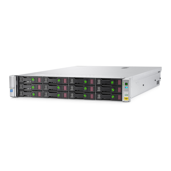
Page 9: Hpe Storeonce 3500 Series Components
Heatsink Processor DIMM System I/O board Drive HPE StoreOnce 3500 Series Components The HPE StoreOnce 3520 System and HPE StoreOnce 3540 System are based on an HPE ProLiant DL380 Gen9 server. Both models have a base configuration of 12 LFF disks, with basic storage capacity capped at 50% of the available usable capacity. - Page 10 Part Spares Part Number Description Hot plug Backplane 777284-001 SPS-PCA DL360/380 12- LFF SAS Backplane Fan module 777286-001 SPS-Fan Module (High PERF) DL38x Gen9 Processor heatsink 777290-001 SPS-Heatsink ASSYSTD 105WDL380 Fan cage 777294-001 SPS-FAN CAGE DL38x Cable, HD Mini SAS to 694008–002 Cable, HD Mini SAS to Mini SAS, 16 inch...
-
Page 11: Hpe Storeonce 3500 And 5100 Mechanical And System Components
HPE StoreOnce 3500 and 5100 mechanical and system components Figure 3: HPE 3500 and HPE 5100 Mechanical Components Figure 4: HPE 3500 and HPE 5100 System Components HPE StoreOnce 3500 and 5100 mechanical and system components... -
Page 12: Hpe Storeonce 5100 System Components
Access panel Fan cage PCI riser Drive cage DIMMs Heatsink Processor Power supply System board assembly Hard drive For a rear view drawing of the HPE StoreOnce 3500 Series, see Figure 5. HPE StoreOnce 5100 System Components The HPE StoreOnce 5100 System is based on an HPE ProLiant DL380 Gen9 server. It has a base configuration of 12 LFF disks for data storage and two disks for the operating system. - Page 13 Part Spares Part Number Description Hot plug SAS expander 761879-001 SPS-BD Smart Array PCIe SAS Expander Cable, HD Mini SAS to 694008–002 Cable, HD Mini SAS to Mini SAS, 16 inch Mini SAS, 16 inch 3500/5100 between the 3500/5100 Defender to SAS expander and the shiner p1224...
-
Page 14: Hpe Storeonce 5100 Mechanical And System Components
Part Spares Part Number Description Hot plug PCIe riser 2 PCA (for 777283-001 SPS-PCA dl380 3-S 2 PCIe slots 4 to 6) x16 x8 PCI-E riser2 Backplane for data disks 777284-001 SPS-PCA DL360/380 12-LFF SAS Backplane Fan module 777286-001 SPS-Fan Module (High PERF) DL38x Gen9 Processor heatsink 777290-001... -
Page 15: Hpe Storeonce 5100 System Capacity Upgrade Kit Components
1Gb RJ45 Port 2 1Gb RJ45 Port 1 (eth0) iLO4 connector USB connectors Rear UID LED HPE StoreOnce 5100 System Capacity Upgrade Kit Components The HPE StoreOnce 5100 System (48 TB) Capacity Upgrade Kit (BB916A) is a 2U disk enclosure containing twelve 4 TB disks. - Page 16 Part Spares Part Number Description Hot plug? HP external 1 m (3 ft) HD 716195–B21 Mini-SAS x 4 to HD Mini- SAS x 4 cable supplied with the product HP external 0.5 m (1.5 ft) 691970–001 HD Mini-SAS x 4 to HD...
-
Page 17: Hpe Storeonce 5100 System Capacity Upgrade System Components
Fibre Channel SAN can be swapped like for like. The following table lists the part numbers for HPE StoreOnce Optional Hardware. Optional Hardware is supported with the HPE StoreOnce 5100 System and HPE StoreOnce 3500 Series. It is not supported with the HPE StoreOnce 3100 System. Table 6: Optional Hardware Part Numbers... - Page 18 Description Part Part number Hot plug? 10GbE SFP transceiver SPS-SFP+,10G BLc,SR 456096-001 8Gb FC card SPS-BD, HBA, 82q DP 489191-001 FC PCIe 8Gb FC transceiver SPS-SFP, 8GB, FC 468508-001 SHORT WAVE 16Gb FC card 16GB FC Card 699765-001 16Gb FC transceiver SPS-16Gb SFP+SW 793443-001 Industrial XCVR 1 Pack...
-
Page 19: General Precautions And Safety Guidelines
General precautions and safety guidelines Required tools The following items are required for some replacement procedures: • T-8 Torx screwdriver • T-10 Torx screwdriver • T-15 Torx screwdriver • Phillips screwdriver Component replacement guidelines CAUTION: Removing a component significantly changes the air flow within the enclosure. Components must be installed for the enclosure to cool properly. -
Page 20: Preventing Electrostatic Discharge
If the product sustains damage requiring service, disconnect the product from the AC electrical outlet and refer servicing to an HPE authorized service provider. Examples of damage requiring service include: • The power cord, extension cord, or plug has been damaged. •... -
Page 21: Identifying Problems
Identifying problems POST messages and troubleshooting The HPE StoreOnce Management Console (GUI and Command Line Interface) are the primary sources of troubleshooting information. However, they do not capture power-on self-test hardware-related issues. Always refer to the appropriate HPE ProLiant Gen9 Maintenance and Service Guide for Power-On Self-Test (POST) information. -
Page 22: Using The Storeonce Cli To Identify A Problem
Using the StoreOnce CLI to identify a problem Overview The following StoreOnce CLI commands can also be used to identify hardware problems and to navigate the hardware tree for details about a specific component. • hardware show problems • hardware show status <Dev-id> The following example illustrates how to use the StoreOnce CLI commands to find out more about the disk problems we have identified on the StoreOnce GUI. - Page 23 p1224 Storage System 051dbf3f-0000-1000-8017-533646303433 DEGRADED Drive Cage 5001438030123680 DEGRADED Pools pools-1 DEGRADED Controller 1 50014380266A0140 # hardware show status 5001438030123680 Name Dev-id Status ----------------------- ---------------------- -------- Drive Cage 5001438030123680 DEGRADED Disk 5000C50076A2E72F 5000C50076A2E72F Disk 5000C500768723A7 5000C500768723A7 Disk 5000C500768AF62B 5000C500768AF62B Disk 5000C5007689EC7B 5000C5007689EC7B Disk 5000C50076A07ACB 5000C50076A07ACB...
-
Page 24: Leds And Problem Diagnosis
capacity = 4.00 TB driveType = HDD = 7200 totalPowerOnHours = 5351 ..Dev-id = Drive_Missing_b1000082 Status = MISSING message = The drive is missing or has failed. type = drive model serialNumber firmwareVersion location = Port: 1I Box: 1 Bay: 8 volumeName = LUN_C3_P1_V1 capacity... -
Page 25: Front Panel Leds
Front panel LEDs Figure 7: Front panel LEDs for HPE StoreOnce 3500 Series and HPE StoreOnce 5100 System System health LED Power LED and on/off button NIC status LED UID LED Front panel LEDs and buttons behavior Description Status Health LED* Solid green = Normal Flashing green (1 Hz/cycle per sec) = iLO is rebooting... - Page 26 †Facility power is not present, power cord is not attached, no power supplies are installed, power supply failure has occurred, or the power button cable is disconnected. Figure 8: Front panel LEDs, HPE StoreOnce 3100 System UID LED NIC status LED...
-
Page 27: Disk Drive Leds
Disk drive LEDs Figure 9: Disk drive LEDs (in servers) Drive locate LED Solid blue = The drive is being identified by a host application. Flashing blue = The drive carrier firmware is being updated or requires an update. Disk activity ring LED Off = No drive activity Rotating green = Drive activity Do not remove LED... -
Page 28: Rear Panel Leds
Rear panel LEDs Figure 10: Rear panel LEDs, HPE StoreOnce 3100 System Figure 11: Rear panel LEDs for HPE StoreOnce 3500 Series and HPE StoreOnce 5100 System Table 7: Rear panel LED behavior Item Description Status UID LED Off = Deactivated... -
Page 29: Storage Enclosure Leds (Hpe Storeonce 5100 System Only)
Item Description Status Power supply 2 LED Off = System is off or power supply has failed. (optional on HPE 3100) Solid green = Normal Power supply 1 LED Off = System is off or power supply has failed. Solid green = Normal Storage enclosure LEDs (HPE StoreOnce 5100 System only) Front View LEDs Figure 12: Capacity Upgrade front view... -
Page 30: Rear View Leds
Indicator Display Description Blue on Location requested. Safe to power off. Blue flashing Location requested. Do not power off. Indicates that maintenance is in progress. For example, firmware updating. Disk drive LEDs Table 9: Disk drive status LEDs Indicator Display Description Status LED Green on, amber off... - Page 31 1. Fan locate UID 2. Fan status LED 3. Pullout tab with serial number label 4. I/O module status LED 5. I/O module locate UID 6. Data ports 7. Data port status LEDs 8. Seven-segment display 9. System locate UID button 10.
-
Page 32: Hpe Storeonce 5100 System Expansion Shelf Error Messages
Table 12: I/O module status LEDs Indicator Display Description 7–segment display Indicates the enclosure number or an error/warning code Data ports (DP-1, DP-2) Green on, amber off Link at high speed with no activity Green flashing, amber off Link at high speed with activity Green on, amber on Link at low speed with no activity Green flashing, amber on... -
Page 33: I/O Module Errors
I/O module errors Error code Error detail Recommended action Error in Expander 1. Remove the module, wait 10 seconds, reinsert the communication module. 2. If the error persists, then check for new firmware releases Permanent error in ESP and upgrade the enclosure firmware. New firmware NVRAM I2C Bus versions, containing new features and defect fixes, are released periodically. -
Page 34: Thermal Control Errors
Thermal control errors Error code Error detail Recommended action Permanent error in 1. Remove the module, wait 10 seconds, reinsert the temperature sensor I2C bus module. 2. If the error persists, then check for new firmware releases Error reading data from and upgrade the enclosure firmware. -
Page 35: Power Supply Communication Errors
Error code Error detail Recommended action Input power loss in Power This warning can also be caused by a failed power Supply module 1 supply. 1. If cabling was not the root cause, troubleshoot by Input power loss in Power reinserting each power supply in turn. -
Page 36: Powering On And Off, Firmware Upgrades, And Other Processes
Powering on and off, firmware upgrades, and other processes Preparing for StoreOnce maintenance Many of the maintenance procedures described in this guide require the system to be powered off. Advise users of the Maintenance window when the HPE StoreOnce System will be unavailable and use the StoreOnce GUI or CLI to power off cleanly and then disconnect the system from the power supply. -
Page 37: Upgrading Bios Or Hardware Firmware Components
system disable remoteeventsuppression "XYZ Maintenance" Upgrading BIOS or hardware firmware components Do not upgrade BIOS or hardware firmware components individually using downloads from the HPE Support website because currently supported firmware component updates are already embedded within the StoreOnce software. Always use the StoreOnce CLI or the StoreOnce GUI to implement BIOS and hardware firmware component checks and updates. -
Page 38: Updating Firmware Using The Storeonce Cli
Updating firmware using the StoreOnce CLI Procedure 1. To show the status of firmware, run the StoreOnce CLI command: # hardware show firmware <node|storage|all> 2. To see if any firmware needs upgrading, check the Action column. IMPORTANT: Do not shut down or reboot your system or any system component until the final step. Special instructions may apply. -
Page 39: Running A System Self Test
External Network Check: [RESULT] PASSED ### SAS CONFIGURATION REPORT ################################################## Sas Configuration Check is supported only on HP StoreOnce multinode, 5500 and 4900 backup products. ### NOTE ###################################################################### For any warning or error messages in this report, please consult the... -
Page 40: Hpresetpassword Account
action. ### END ####################################################################### Command Successful HPresetpassword account The purpose of the HPresetpassword account The HPresetpassword account provides a method for the local Admin user to recover the Admin password back to a default state. • username = HPresetpassword • default password = hpresetpassword Best practice is to change the default password after installation. - Page 41 3. When prompted for the password enter the current password. The default is hpresetpassword, but if you are following best practices you will have changed this Password after installation. 4. Once logged in a list of available commands will be presented. 5.
-
Page 42: Replacing The Storeonce System Motherboard
Before replacing the motherboard, make a note of PCIe slot allocation and SAS cabling. • HPE StoreOnce 3100 System: Only one PCIe slot is used, slot 1 for the RAID controller card. • HPE StoreOnce 3500 Series and HPE StoreOnce 5100 System: This system supports Optional Hardware. -
Page 43: Motherboard Spares Part Number And System Maintenance Switch
Motherboard spares part number and System Maintenance switch The motherboard for the HPE StoreOnce 3100 System, HPE StoreOnce 3500, and 5100 System is the standard DL360/DL380 Gen9 motherboard, spares part number 775400-001. See the DL360p Gen 9 Maintenance and Service Guide and DL380p Gen 9 Maintenance and Service Guide for more information about replacing the motherboard. - Page 44 DIMM 2 Ch2, slot 9, B DIMM 1 Ch1, slot 12, A DIMM 2 Ch2, slot 9, B HPE StoreOnce 3100 DIMM 1 Ch1, slot 12, A System DIMM 2 Ch2, slot 9, B The locations of DIMM slots are also shown on the StoreOnce hood label inside the server.
-
Page 45: After Replacing The Motherboard-Bios And Ilo Configuration
Figure 16: DIMM locations for HPE StoreOnce 3500 Series not used Ch 2 Ch 1 Figure 17: DIMM locations for HPE StoreOnce 3100 System After replacing the motherboard—BIOS and iLO configuration Configure the RBSU (ROM-Based Setup Utility) settings BEFORE connecting the FC, network, and SAS cables to the server and BEFORE the system boots into the StoreOnce software, that is, during the server POST sequence. - Page 46 To access System Utilities, press F9 in the ProLiant POST screen. Select System Configuration Select BIOS/Platform Configuration (RBSU) — System Options. Replacing the StoreOnce System motherboard...
- Page 47 Change the RBSU settings, as shown in the tables in the next section. Press F10 to save. Then press ESC until the System Utilities menu is displayed. At this point, you can either press ESC to exit System Utilities and continue with the system reboot. Or, if there are no DHCP–assigned IP addresses, you can manually configure iLO using the local console.
- Page 48 Select Network Options. 10. Configure your network settings and press F10 to save. 11. Press ESC until you exit System Utilities and can continue with the system reboot. 12. Check that an existing iLO4 Advanced license is loaded. If it is not, add it: Replacing the StoreOnce System motherboard...
-
Page 49: Rbsu Settings
14. After power-up, it is necessary to rewrite warranty serial numbers into BIOS. Contact HPE Support for assistance in rewriting warranty serial numbers. RBSU settings Table 14: RBSU settings for HPE StoreOnce 3100 System Top menu item Sub menu 1... -
Page 50: Ilo4 Settings
Sub menu 1 Sub menu 2 Current default Change to... state Boot options Boot Mode UEFI Mode Legacy BIOS mode Power Management HP Power Profile Balanced Power Maximum Options and Performance performance Performance Advanced Node interleaving Disabled Enabled - i.e Turn... -
Page 51: Replacing The P1224 Raid Controller And Components
Part numbers Replacement spares part numbers for the p1224 card, SuperCapacitor module, and SAS expander card are as follows: • HP p1224 RAID controller with 1GB cache module: 842475-001 (minimum firmware revision = 2.50) • SuperCapacitor: 660093-001 • SAS expander card (not used with HPE StoreOnce 3100 System): 761879-001 For information about the part numbers for replacement internal SAS cables, see Internal SAS cabling on page 51. -
Page 52: Hpe Storeonce 3500 Series Internal Sas Cabling
From SAS cable Port on backplane Port on RAID controller card 780423–001 HPE StoreOnce 3500 Series internal SAS cabling Figure 19: Internal SAS cabling for HPE StoreOnce 3500 Series Item From Cable Port 1, RAID controller (slot Port 1, SAS expander (slot 2) 729357–001 Port 5, SAS expander Port 1, backplane 784627–001 (kit for all three... -
Page 53: Hpe Storeonce 5100 System Internal Sas Cabling
Port 3, backplane System boot and RAID controller failure HPE StoreOnce 3100, 3520 and 3540 Systems boot from the p1224 RAID controller that is also connected to the customer data storage disks. HPE StoreOnce 5100 Systems boot from the onboard smart array controller which is connected to the two OS disk drives in the rear of the server. -
Page 54: Replacing The Raid Components
The p1224 RAID controller card is located in: • HPE StoreOnce 3100 System: PCIe slot 1 and is connected to the backplane. • HPE StoreOnce 3500 Series and HPE StoreOnce 5100 System: PCIe slot 3 and is connected to the SAS expander card in slot 2 and to the backplane. -
Page 55: The Raid Cache Module And Supercapacitor
The RAID cache module and SuperCapacitor There is one SuperCapacitor and cache module for each RAID Controller. The RAID cache module is slotted onto the RAID card; the SuperCapacitor is located in the center of the unit, clipped to the floor of the chassis behind the disk cage. -
Page 56: Replacing The Hpe Sas Expander Card
NOTE: Tuck the mini-SAS cables to be routed to the backplane into the side of the chassis. See Figures 17 and Replacing the HPE SAS expander card The following example describes how to replace the p1224 card. The general procedure is the same to access the SAS expander card or the SuperCapacitor cache module. - Page 57 The HPE StoreOnce 3500 Series and HPE StoreOnce 5100 System may have a PCIe 10GbE Network or Fibre Channel card in slot 1. Verify that this card has not been dislodged. Replace the PCIe riser cage and the server cover, as described in the appropriate HP ProLiant Maintenance and Service guide.
-
Page 58: Disk Replacement
Disk replacement Disk numbering This chapter describes how to replace individual disks within a RAID set. NOTE: For instructions on how to connect additional storage to an HPE StoreOnce 5100 System by adding a capacity upgrade enclosure (not available with the HPE StoreOnce 3500 Series and HPE StoreOnce 3100 System), see the printed documentation supplied with the additional storage. -
Page 59: Hot Spare Disk And Leds On The Hpe Storeonce 5100 System
100%. • HPE StoreOnce 3100 System: If more than one disk fails, then the data and operating system are lost and a “Quick Restore” of the appliance OS will be required before the unit can be used again. -
Page 60: Replacing A Hot-Plug Hard Disk
2 TB HDD HPE StoreOnce 3520 System (12 653948-001 disks) HPE StoreOnce 3100 System (4 disks) Replacing a hot-plug hard disk Procedure 1. Identify the disk that has failed as described above. NOTE: Remember you can use the Beacon LED to identify the physical disk in the storage controller or expansion shelves. - Page 61 6. Run the StoreOnce CLI command, hardware show firmware, to check that the firmware on the new disk is correct; it will be listed under the storage details. Run the StoreOnce CLI command, hardware update firmware, with appropriate parameters to update it, if necessary. See the HP StoreOnce Backup CLI Reference Guide for more details.
-
Page 62: Rebuilding Storage If Multiple Disks Fail And A Raidset Is Broken
Rebuilding storage if multiple disks fail and a RAIDset is broken This section explains how to rebuild your storage in the event of a complete data loss. This should be done under the guidance of HPE Support. After the failed disks have been replaced it will be necessary to remove the old filesystem configuration and rebuild a new one as follows: Procedure 1. -
Page 63: Storeonce Optional Hardware
Support for StoreOnce Optional Hardware NOTE: This chapter is not applicable to the HPE StoreOnce 3100 System because it does not support Optional Hardware. The HPE StoreOnce 3500 Series and HPE StoreOnce 5100 System support the addition of 10 GbE Network cards and Fibre Channel cards. -
Page 64: Replacing Optional Hardware Cards
Short message Error message Description Recommended Action Incorrect Card installed in the The card is in the wrong It is likely that a card has wrong PCI-E slot PCIe slot. been installed in the wrong slot. Put the card in the correct slot and try to activate again. -
Page 65: Removing And Replacing A Fibre Channel Or 10 Gbe Optical Sfp
device presented on a StoreOnce Fibre Channel port currently uses the WWPN / WWNN of the FC card. StoreOnce generated WWPNs / WWNNs are not used. Replacing the FC card will result in a new Catalyst over Fibre Channel WWPN / WWNN. After replacing a FC card the StoreOnce user will need to re-zone their clients with the new WWPN / WWNN. -
Page 66: Hpe Storeonce 5100 System Capacity Upgrade Expansion Shelves
HPE StoreOnce 5100 System Capacity Upgrade hot- pluggable components NOTE: This chapter is not relevant for the HPE StoreOnce 3500 Series or the HPE StoreOnce 3100 System. The HPE StoreOnce 5100 System supports capacity expansion by the addition of up to five Capacity Upgrade Kits. - Page 67 5. Slide out the I/O module (3) and set aside. 6. Slide the replacement I/O module into the correct bay and swing in the hood latch until it closes. HPE StoreOnce 5100 System Capacity Upgrade expansion shelves...
-
Page 68: Removing And Replacing A Power Supply Module
7. Retighten the captive retainer thumbscrews 8. Replace the I/O cables. SAS IN from RAID controller in server or from previous enclosure SAS OUT to next enclosure 9. Read the LEDs and confirm that the unit is operating. Removing and replacing a power supply module NOTE: If one of the PSUs is removed and reinserted, but the power cord is not reattached, the hardware report will show the failed AC Supply and a TempSensor Failure. -
Page 69: Removing And Replacing A Fan Module
4. Connect the power cable. 5. To ensure the module is operating properly, check the power supply module status LED. Removing and replacing a fan module WARNING: To maintain the correct airflow to the HPE StoreOnce system, this procedure must be completed within 3 minutes. -
Page 70: Replacing The Fan Control Card
Replacing the fan control card This procedure must be performed only after HPE Support determines that the fan control card is the source of the problem and recommends that the fan control card be replaced. CAUTION: This procedure requires removing the enclosure from the rack. Before removing the enclosure, power down the HPE StoreOnce 5100 System. -
Page 71: Removing And Replacing The Power Distribution Board
Insert the new fan control card and slide it sideways to engage it with the retaining pins. Tighten the captive thumbscrew. 10. Attach the fan control card cable. 11. Install the enclosure cover and press the hood latch down to engage the latch. 12. -
Page 72: Removing And Replacing The Enclosure Backplane
Remove the power cables from the backplane. Lift the air guide, pull it toward the front of the enclosure and remove it (2). Loosen the captive thumbscrew on the power distribution board. 10. Slide the power distribution board toward the front of the enclosure and lift it out of the enclosure. 11. - Page 73 Remove the fan modules. Remove the enclosure from the rack. Pull the hood latch up and back (1 and 2), and lift the enclosure cover up and remove it (3). 10. Disconnect the following cables from the backplane: Number Cable Front UID health module Fan control card Fan control card...
- Page 74 Number Cable Rear UID health module Power supply Power supply 11. Remove the eight drive cage retaining screws. There are four to a side. NOTE: The StoreOnce System has 12 hard disks and the screws are in the 12LFF HDD Cage location. 12.
-
Page 75: Removing And Replacing An Enclosure
28. Reconnect all cables to the enclosure, including the power cables. 29. When the enclosure has completed its power-on sequence, check all enclosure status LEDs to ensure that the enclosure is operating properly. Removing and replacing an enclosure This operation is required before the user can carry out a number of the other tasks described in this chapter. Procedure Power down the HPE StoreOnce 5100 System. - Page 76 Reattach the rear hold-down bracket. 10. Reinstall any items that were removed before removing the enclosure. a. Install the I/O module. b. Install the power supplies. c. Install the fan modules. d. Install the disk drives in the same bays as they were before maintenance. 11.
- Page 77 Figure 28: SAS cabling showing five storage enclosures below the head server JBOD1 JBOD2 JBOD3 JBOD4 JBOD5 SAS connector on RAID controller on head unit P1 connector on I/O module (SAS IN from P2 connector on I/O module (SAS OUT to head unit or previous expansion shelf) next expansion shelf) 12.
-
Page 78: The Qr Iso Image
The QR ISO image The StoreOnce QR ISO image In the rare occurrence of a complete system failure, it may be necessary to reinstall the product software. This task is normally carried out on the recommendation and under the supervision of HPE Support. CAUTION: The Quick Restore process will delete all stored data and configuration settings returning your product to factory default settings. -
Page 79: Delete Storage
a. Place your HPE USB drive key (minimum size 8 GB flash stick) in an available USB port. b. Select the HPE USB Key Utility shortcut in the HPE System Tools folder. 3. Once all steps are completed, remove the USB stick from the Windows PC. Delete storage Before running QR, it is advisable to remove all configured storage on the appliance. -
Page 80: Performing A Configuration Restore
System ID that can be found on the Device Management page of the StoreOnce Management Console. Its value is assigned in the factory set up process and is a 12–character string in the format HP<SerialNumber of Appliance>. Procedure 1. Check the Cluster ID against the value shown in the configuration text file, <config_filename>.txt,... - Page 81 • Adding X,XXXGB... • Formatted XXGB, which means that the storage and file system has been configured and is ready for use. Parity initialization may still be in progress. The following output is an example; the values shown may not match your appliance-specific values. # system show status Status ------...
-
Page 82: Support And Other Resources
IMPORTANT: Access to some updates might require product entitlement when accessed through the Hewlett Packard Enterprise Support Center. You must have an HP Passport set up with relevant entitlements. Customer self repair Hewlett Packard Enterprise customer self repair (CSR) programs allow you to repair your product. If a CSR part needs to be replaced, it will be shipped directly to you so that you can install it at your convenience. -
Page 83: Remote Support
For more information about CSR, contact your local service provider or go to the CSR website: http://www.hpe.com/support/selfrepair Remote support Remote support is available with supported devices as part of your warranty or contractual support agreement. It provides intelligent event diagnosis, and automatic, secure submission of hardware event notifications to Hewlett Packard Enterprise, which will initiate a fast and accurate resolution based on your product's service level. -
Page 84: Documentation Feedback
www.hpe.com/info/reach For Hewlett Packard Enterprise product environmental and safety information and compliance data, including RoHS and REACH, see: www.hpe.com/info/ecodata For Hewlett Packard Enterprise environmental information, including company programs, product recycling, and energy efficiency, see: www.hpe.com/info/environment Documentation feedback Hewlett Packard Enterprise is committed to providing documentation that meets your needs. To help us improve the documentation, send any errors, suggestions, or comments to Documentation Feedback (docsfeedback@hpe.com). -
Page 85: Additional Regulatory Information
Additional regulatory information Belarus Kazakhstan Russia marking Manufacturer and Local Representative Information Manufacturer information: • Hewlett Packard Enterprise Company, 3000 Hanover Street, Palo Alto, CA 94304 U.S. Local representative information Russian: • Russia: • Belarus: • Kazakhstan: Local representative information Kazakh: •... -
Page 86: Turkey Rohs Material Content Declaration
• YWW, where Y indicates the year counting from within each new decade, with 2000 as the starting point; for example, 238: 2 for 2002 and 38 for the week of September 9. In addition, 2010 is indicated by 0, 2011 by 1, 2012 by 2, 2013 by 3, and so forth.