Table of Contents
Advertisement
1.
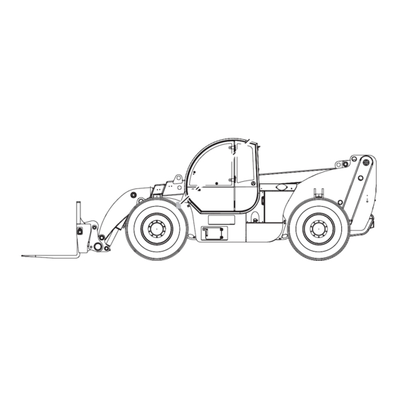
Service and Repair Manual
From GTH1513B-001
(Perkins Tier 4i)
From GTH1516M-340
(Deutz Tier 4i)
Serial Number Range
To GTH1515B-339
To GTH1516M-599
From GTH15M-600
From GTH1513B-001
To GTH1515B-339
plus 24273
From GTH1516M-340
To GTH1516M-599
From GTH15M-600
This manual includes:
Electrical and Hydraulic
For detailed maintenance
procedures, Refer to the
appropriate Maintenance
Manual for your machine.
Part No. 1272857
Rev A1
September 2016
Advertisement
Table of Contents

Related Manuals for Genie GTH-1544


Summary of Contents for Genie GTH-1544
- Page 1 Service and Repair Manual Serial Number Range GTH-1544 This manual includes: From GTH1513B-001 (Perkins Tier 4i) Repair procedures To GTH1515B-339 Fault Codes From GTH1516M-340 To GTH1516M-599 Electrical and Hydraulic From GTH15M-600 Schematics For detailed maintenance GTH-1544 procedures, Refer to the...
-
Page 2: Introduction
Genie has endeavored to deliver the highest degree of accuracy possible. However, continuous operating instructions in the Genie GTH-1544 improvement of our products is a Genie policy. Operator's Manual before attempting any Therefore, product specifi cations are subject to maintenance or repair procedure. -
Page 3: Gth-1544
Serial Number Legend REFERENCE EXAMPLES: Electronic Version Section 2_Specifi cations, Machine Specifi cations Section 3_Repair Procedure, 3-2 Click on any procedure or page number Section 4_Fault Codes, 4-3 highlighted in blue to view the update. Section 5_Schematics, 5-3 Part No.1272857 GTH-1544... - Page 4 Procedure / Page / Description REFERENCE EXAMPLES: Electronic Version Section 2_Specifi cations, Machine Specifi cations Section 3_Repair Procedure, 3-2 Click on any procedure or page number Section 4_Fault Codes, 4-3 highlighted in blue to view the update. Section 5_Schematics, 5-3 GTH-1544 Part No. 1272857...
- Page 5 September 2016 Serial Number Legend Part No.1272857 GTH-1544...
- Page 6 September 2016 This page intentionally left blank. GTH-1544 Part No. 1272857...
- Page 7 You read, understand and obey: - manufacturer’s instructions and safety rules - employer’s safety rules and worksite regulations - applicable governmental regulations You have the appropriate tools, lifting equipment and a suitable workshop. Part No.1272857 GTH-1544...
- Page 8 Be sure to wear protective eye wear and other protective clothing if the situation warrants it. Be aware of potential crushing hazards such as moving parts, free swinging or unsecured components when lifting or placing loads. Always wear approved steel-toed shoes. viii GTH-1544 Part No. 1272857...
-
Page 9: Table Of Contents
SAE and Metric Fasteners Torque Charts ..........2 - 11 Section 3 Repair Procedures Introduction .....................3 - 1 Boom Components Boom Proximity Switch..............3 - 2 Boom ....................3 - 3 Boom Lift Cylinder ..............3 - 11 Boom Extend Cylinder..............3 - 12 Part No.1272857 GTH-1544... -
Page 10: Table Of Contents
Section 4 Fault Codes Introduction .....................4 - 1 Diagnostic Display ..................4 - 2 Engine Fault Codes - Models with Deutz TCD 4.1 L4 ......4 - 3 How to Troubleshoot the Perkins 1204E-E44TA Engine ......4 - 42 GTH-1544 Part No. 1272857... - Page 11 TABLE OF CONTENTS Section 5 Schematics Introduction .....................5 - 1 Electrical and Hydraulic Symbol Legends ..........5 - 2 Electrical Schematic ................5 - 3 Hydraulic Schematic - Deutz Engine ............5 - 34 Hydraulic Schematic - Perkins Engine ..........5 - 36 Part No.1272857 GTH-1544...
-
Page 12: Part
September 2016 This page intentionally left blank. GTH-1544 Part No. 1272857... -
Page 13: Machine Specifi Cations
Lug pattern 10 x 13.189 Operator's Manual. Wheel diameter 53 in 135 cm Wheel width 18 in 46.5 cm Continuous improvement of our products is a Genie policy. Product specifi cations are subject to change without notice. Part No.1272857 GTH-1544... -
Page 14: Performance Specifi Cations
10206 kg Fork tilt up 7 seconds Lift capacity, maximum 15000 lbs Fork tilt down 7 seconds 6804 kg Continuous improvement of our products is a Genie policy. Product specifi cations are subject to change without notice. GTH-1544 Part No. 1272857... -
Page 15: Hydraulic Specifi Cations
Genie specifi cations require additional equipment and special installation instructions for the approved optional fl uids. Consult the Genie Service Department before use. Continuous improvement of our products is a Genie policy. Product specifi cations are subject to change without notice. Part No.1272857 GTH-1544... -
Page 16: Hydraulic Component Specifi Cations
0.73 cu in (Deutz Confi guration) 12 cc Continuous improvement of our products Flow rate @ 2200 rpm 8 gpm is a Genie policy. Product specifi cations are (Deutz Confi guration) 31 L/min subject to change without notice. Displacement 0.98 cu in (Perkins Confi... -
Page 17: Function Manifold Specifi Cations
28 bar (measured at test port TP3) Air Conditioner Refrigerant Specifi cations System Full Charge R134a 2 lbs 3 oz Continuous improvement of our products is a Genie policy. Product specifi cations are subject to change without notice. Part No.1272857 GTH-1544... -
Page 18: Perkins 1204E-E44Ta Engine
0°F to the Engine Operation and Maintenance Manual on your machine. Reserve capacity @ 25A 200 minutes rate Continuous improvement of our products is a Genie policy. Product specifi cations are subject to change without notice. GTH-1544 Part No. 1272857... -
Page 19: Deutz Tcd 4.1 L4 Engine
Engine Operation and Maintenance Manual on Quantity your machine. Cold cranking ampere 1000A @ 0°F Reserve capacity @ 25A 200 minutes rate Continuous improvement of our products is a Genie policy. Product specifi cations are subject to change without notice. Part No.1272857 GTH-1544... -
Page 20: Dana Integral Gear Box Shift On Fly
Axle Maintenance and Repair Manual (Dana part number MO213S20). Dana Axle Maintenance and Repair Manual Genie part number 57.4700.0008 (Genie Instructions Library) Continuous improvement of our products is a Genie policy. Product specifi cations are subject to change without notice. GTH-1544 Part No. 1272857... -
Page 21: Hydraulic Hose And Fitting Torque Specifi Cations
Your machine is equipped with Parker Seal-Lok™ ORFS or 37° JIC fi ttings and hose ends. 14 ft-lbs / 19 Nm Genie specifi cations require that fi ttings and hose 23 ft-lbs / 31.2 Nm ends be torqued to specifi cation when they are 36 ft-lbs / 54.2 Nm... -
Page 22: Torque Procedure
3 Working clockwise on the body hex fi tting, They are not standard SAE size O-rings. They are make a second mark with a permanent ink available in the O-ring fi eld service kit (Genie part marker to indicate the proper tightening number 49612). - Page 23 34. 1 48. 6 64. 9 69. 7 94. 5 92. 2 30. 1 40. 8 54. 3 77. 4 46. 9 63. 6 62. 5 84. 8 64. 5 87. 5 86. 2 1055 1233 Part No.1272857 GTH-1544 2-11...
- Page 24 Section 2 • Specifications September 2016 This page intentionally left blank. 2-12 GTH-1544 Part No. 1272857...
- Page 25 Be sure that all necessary tools and parts are serious injury. available and ready for use. Indicates a potentially hazardous WARNING Use only Genie approved replacement parts. situation which, if not avoided, could result in death or serious Read each procedure completely and adhere injury.
-
Page 26: Boom Proximity Switch
Result: The light of the proximity switch drive circuit and the chassis sway circuit. Both the assembly turns on. The switch is functioning drive and the chassis sway functions are disabled correctly. when the boom is raised to 50° or higher. GTH-1544 Part No. 1272857... -
Page 27: Boom
Result: The light of the proximity switch assembly is not illuminated. The proximity switch is properly calibrated. Result: The light of the proximity switch assembly is illuminated. The proximity switch is not calibrated correctly. Repeat the procedure beginning with step 4. Part No.1272857 GTH-1544... - Page 28 6 Use a soft metal drift to remove the pivot pin. 7 Using the overhead crane, lift and remove the fork frame from the boom. Crushing hazard. The fork CAUTION frame could fall if not properly supported when the lock pin is removed from the machine. GTH-1544 Part No. 1272857...
- Page 29 2° BOOM SECTION CHAINS ANCHORAGE 1° BOOM SECTION CHAINS ANCHORAGE Part No.1272857 GTH-1544...
- Page 30 7 Remove the tensioners "e" from the chains, by 16 Install the pulley "a" and pin "b" previously pulling out the retaining fasteners "f". removed from the pivot end of the boom. 1° BOOM SECTION CHAINS ANCHORAGE 3° BOOM SECTION CHAINS ANCHORAGE GTH-1544 Part No. 1272857...
- Page 31 7 Using a soft metal drift, remove the slave cylinder locking pin from the boom support. Crushing hazard. The cylinder DANGER will fall if not properly supported when the pivot pin is removed from the machine. Part No.1272857 GTH-1544...
- Page 32 Pull them out from below the boom. 7 At the fork end of the boom, disconnect the fl exible hoses from the fork tilt cylinder (ref. “f”) and the attachment lock/unlock cylinder (ref. “g”). GTH-1544 Part No. 1272857...
- Page 33 19 Attach lifting straps to the second and third chain tensioners and pull it out of the boom. boom sections; handle them very slowly, paying attention to the position of the straps to make sure the boom sections are always horizontal. Part No.1272857 GTH-1544...
- Page 34 24 Remove all the front pads in the second boom section. 25 Attach lifting straps to the third boom section. Pull the section out and handle very slowly, paying attention to the position of the straps to make sure the section is always horizontal. 3-10 GTH-1544 Part No. 1272857...
-
Page 35: Boom Lift Cylinder
Support the cylinder. Do not apply any lifting pressure. 4 Remove the fasteners securing the lift cylinder barrel-end pivot pin to the chassis. 5 Use a soft metal drift to remove the pivot pin. Part No.1272857 GTH-1544 3-11... -
Page 36: Boom Extend Cylinder
The third section 6 Remove the cylinder screws, rod side. features some holes matching the cylinder retaining screws, when the boom is retracted. 7 Remove the retaining fasteners securing the extend cylinder barrel-end pivot pin. 3-12 GTH-1544 Part No. 1272857... -
Page 37: Fork Level Cylinder
Loosen hydraulic connections very slowly to allow the oil pressure to dissipate gradually. Do not allow oil to squirt or spray. Component damage hazard. NOTICE Hoses can be damaged if they are kinked or pinched. Part No.1272857 GTH-1544 3-13... - Page 38 fi rst boom section, and pull the hoses out of the boom. 9 Get underneath the boom, disconnect the hoses from fi ttings “c”, then pull out the hoses from underneath the boom. 3-14 GTH-1544 Part No. 1272857...
-
Page 39: Fork Tilt Cylinder
Cap the cylinder fi ttings. Bodily injury hazard. Spraying WARNING hydraulic oil can penetrate and burn skin. Loosen hydraulic connections very slowly to allow the oil pressure to dissipate gradually. Do not allow oil to squirt or spray. Part No.1272857 GTH-1544 3-15... - Page 40 8 Using a soft metal drift and a hammer, remove the pivot pin. 9 Carefully lift and remove the cylinder from the machine. Crushing hazard. The cylinder DANGER could fall if not properly supported when removed from the machine. 3-16 GTH-1544 Part No. 1272857...
-
Page 41: Operator's Compartment
Do not allow oil to For further information or assistance, consult the squirt or spray. Genie Service Department. 7 Remove the cover which is located under the Bodily injury hazard. This WARNING cab. - Page 42 Do not lift the cab using a strap from an overhead crane. Bolt torque specifi cation Operator's cab mounting bolts 155 ft-lbs 210 Nm (plus Locktite compound) 3-18 GTH-1544 Part No. 1272857...
-
Page 43: Machine Controls
3 Remove the upper part of the dashboard. 4 Remove the transmission control lever. 5 Remove the light control lever. 6 Remove the screws which secure the steering column to the frame. 7 Remove the steering column. Part No.1272857 GTH-1544 3-19... - Page 44 5 Remove the fasteners securing the joystick to the mount panel. Remove the joystick. Joystick port orientation 3-20 GTH-1544 Part No. 1272857...
- Page 45 Loosen hydraulic connections very slowly to allow the oil pressure to dissipate gradually. Do not allow oil to squirt or spray. 8 Remove the retaining fasteners securing the brake pedal. Remove the brake pedal. Part No.1272857 GTH-1544 3-21...
-
Page 46: Fuel And Hydraulic Tanks
9 Tag, disconnect and plug the fuel hoses. without these skills and tools could result in death or serious 10 Remove the fi ller cap from the fuel tank. injury and signifi cant component damage. Dealer service is strongly recommended. 3-22 GTH-1544 Part No. 1272857... - Page 47 19 Using a lifting strap and an overhead crane, remove the tanks from the machine. Crushing hazard. The tanks WARNING could become unbalanced and fall if not properly supported when removed from the machine. Part No.1272857 GTH-1544 3-23...
-
Page 48: Engines
(Perkins part number KENR9116-01). To learn the specifi cations of and how to use the fault codes, refer to Section 5, Fault Codes. Perkins 1204E-E44TA Operation and Maintenance Manual Genie part number 57.4700.0009 Perkins 1204E-E44TA Service Manual Genie part number 57.4700.0012... -
Page 49: Gearbox
Dana Integral Gear Box Shift on Fly damage. Dealer service is Maintenance and Repair Manual required. Genie part number 57.4700.0007 1 Chock the wheels. 2 Remove the fasteners securing the driveshaft to the transmission. Lower the end of the driveshaft to the ground. - Page 50 Remove the axle from the machine. Crushing hazard. The axle will WARNING fall if not properly supported when the fasteners are removed from the machine. Bolt torque specifi cation Axle mounting bolts 515 ft-lbs 700 Nm 3-26 GTH-1544 Part No. 1272857...
-
Page 51: Boom And Steering Function Pump
When testing the pump, crank the engine in one second intervals until the correct pressure is confi rmed. Do not over-pressurize the pump. 6 Remove the pressure gauge and install plug onto port TP1. Part No.1272857 GTH-1544 3-27... - Page 52 3 Remove the engine cover to easily reach the remove the pump from the machine. pumps. Crushing hazard. The pump WARNING will fall if not properly supported when the fasteners are removed from the machine. 3-28 GTH-1544 Part No. 1272857...
- Page 53 Install the hose retaining rings and fasteners. 4 At the case drain at the top of the pump, fi ll the pump with hydraulic fl uid until it reaches the top of the case drain fi tting. Part No.1272857 GTH-1544 3-29...
- Page 54 Turn the adjustment screw clockwise to increase the pressure or counterclockwise to 6 Shut off the engine and inspect for oil leaks. decrease the pressure. Tighten the set screw. 5 Turn the engine off and remove the pressure gauge. 3-30 GTH-1544 Part No. 1272857...
- Page 55 270 bar. The pump is good. Proceed to step 9. Pressure is not within specifi cation. The pressure setting needs to be adjusted. Proceed to step 7. 7 Loosen the set screw for the pressure compensator adjustment screw. Part No.1272857 GTH-1544 3-31...
-
Page 56: Auxiliary Gear Pump
Do not allow oil to squirt or spray. 3 Cap the auxiliary gear pump holes and the hoses ones. 4 Remove the auxiliary gear pump. 3-32 GTH-1544 Part No. 1272857... - Page 57 WARNING hydraulic oil can penetrate and burn skin. Loosen hydraulic connections very slowly to allow the oil pressure to dissipate gradually. Do not allow oil to squirt or spray. 3 Open the hydraulic tank ball valve. Part No.1272857 GTH-1544 3-33...
- Page 58 15 seconds then shut off the engine. 2 Wait 15 seconds, then start the engine again. 3 Allow the engine to run at low idle for 15 seconds and then shut off the engine. 3-34 GTH-1544 Part No. 1272857...
-
Page 59: Hydrostatic Transmission Pump
Result: the pressure gauge connected to test port TP3 reads 406 psi / 28 bar. Pressure is not within specifi cation. Adjust the boost pressure valve "c" located under the pump. 5 Increase the engine speed to 1100 rpm. Part No.1272857 GTH-1544 3-35... - Page 60 3 Remove the cover that is under engine. from the machine. 4 Locate the battery disconnect switch and disconnect the battery from the machine. 5 Remove the retaining fasteners that secure the battery disconnect switch mounting plate. 3-36 GTH-1544 Part No. 1272857...
- Page 61 4 Attach a lifting strap and lift the transmission pump using a overhead crane. 5 Install the hydrostatic transmission pump on the engine. 6 Remove the fi tting caps from the hydrostatic transmission pump. 7 Remove the hoses caps. Part No.1272857 GTH-1544 3-37...
- Page 62 5 Apply the brake pedal and start the engine. Shift the transmission into forward and disengage the emergency brake. 6 Release the brake pedal and slowly increase the engine rpm until the machine starts to move. Apply the brake. 3-38 GTH-1544 Part No. 1272857...
-
Page 63: Function Manifold
4 Turn the engine off, spot the valve on the power steering and open the cap. 5 Adjust the internal hex socket. Turn clockwise to increase the pressure; turn counterclockwise to decrease the pressure. 6 Cap the valve. 7 Repeat this procedure beginning with step 2. Part No.1272857 GTH-1544 3-39... - Page 64 Do not allow oil to squirt or spray. 4 Support and secure the function manifold to a suitable lifting device. Do not apply lighting pressure. 3-40 GTH-1544 Part No. 1272857...
- Page 65 3 Increase the engine speed to maximum rpm. 4 Moving the joystick, retract the boom. Result: the pressure gauge reads 3770 psi / 260 bar. The pump is good. Pressure is not within specifi cation. Set the valve placed above the manifold. Part No.1272857 GTH-1544 3-41...
- Page 66 Do not allow oil to squirt or spray. 4 Tag and disconnect the harness from the manifold. 5 Support and secure the auxiliary function manifold to a suitable lifting device. Do not apply lighting pressure. 3-42 GTH-1544 Part No. 1272857...
- Page 67 3 Increase the engine speed to maximum rpm. 4 Move the joystick to lock/unlock the attachment. Result: the pressure gauge reads 3335 psi / 230 bar. The pump is good. Pressure is not within specifi cation. Set the valve placed above the manifold. Part No.1272857 GTH-1544 3-43...
- Page 68 Function Manifold Components Pos. Function Description Schematic ITEM Boom up/down Hydraulic proportional control A1 -B1 Boom in/out Hydraulic proportional control A2 -B2 Fork tilt Hydraulic proportional control A3 -B3 Load Sensing Relief Valve (3770 psi) 3-44 GTH-1544 Part No. 1272857...
- Page 69 September 2016 Section 3 • Repair Procedures MANIFOLDS Auxiliary Function Manifold Components Pos. Function Description Schematic ITEM Chassis sway function Boom auxiliary line ON/OFF solenoid valve X210 - X211 Relief Valve (3335 psi) Part No.1272857 GTH-1544 3-45...
-
Page 70: Valve Coils
2 Test the coil resistance using a multimeter set to resistance (Ω). Refer to the Valve Coil Resistance Specifi cation table. Result: If the resistance is not within the adjusted specifi cation, plus or minus 10%, replace the coil. 3-46 GTH-1544 Part No. 1272857... - Page 71 September 2016 Section 3 • Repair Procedures MANIFOLDS How to Test a Coil Diode COIL Genie incorporates spike suppressing diodes in all MULTI- of its coils. Properly functioning coil diodes protect METER the electrical circuit by suppressing voltage spikes. Voltage spikes naturally occur within a function circuit following the interruption of electrical current to a coil.
- Page 72 Section 3 • Repair Procedures September 2016 This page intentionally left blank. 3-48 GTH-1544 Part No. 1272857...
- Page 73 Do not allow oil to squirt or spray. General Repair Process Malfunction Identify Troubleshoot discovered symptoms problem still exists Return to Inspect Perform service and test Repair problem solved Part No.1272857 GTH-1544...
-
Page 74: Diagnostic Display
ECM memory. The presence of faults is indicated by the word Note: Additional hardware will be necessary to “SERVICE” (replacing GENIE) on the LCD display access stored codes. which is located on the gauge cluster in the operator's compartment. -
Page 75: Engine Fault Codes - Models With Deutz Tcd 4.1 L4
Sensor error burner dosing valve (DV2) downstream pressure sensor; signal range check low 523913 Sensor error glow plug control diagnostic line voltage; signal range check high 523913 Sensor error glow plug control diagnostic line voltage; signal range check low 523914 Glow plug control; open load Part No.1272857 GTH-1544... - Page 76 Timeout Error of CAN-Receive-Frame AT1IG1; NOX sensor upstream 3224 DLC Error of CAN-Receive-Frame AT1IG1Vol NOX Sensor (SCR-system upstream cat; DPF- system downstream cat); length of frame incorrect 3224 Timeout Error of CAN-Receive-Frame AT1IG1Vol; NOX sensor (SCR-system upstream cat; DPF- system downstream cat) GTH-1544 Part No. 1272857...
- Page 77 Passive Timeout Error of CAN-Receive-Frame TSC1TE; Setpoint 523778 Active Timeout Errorof CAN-Receive-Frame TSC1TR 523779 Passive Timeout Error of CAN-Receive-Frame TSC1TR 523788 Timeout Error of CAN-Transmit-Frame TrbCH; Status Wastegate 523605 Timeout Error of CAN-Receive-Frame TSC1AE; Traction Control 523606 Timeout Error of CAN-Receive-Frame TSC1AR; Retarder Part No.1272857 GTH-1544...
- Page 78 Fan actuator (PWM output); powerstage over temperature Fan actuator (PWM output); short circuit to battery Fan actuator (PWM output); short circuit to ground 1639 Sensor error fan speed; signal range check high 1639 Sensor error fan speed; signal range check low GTH-1544 Part No. 1272857...
- Page 79 Sensor error DV1 & DV2 upstream temperature; signal range check high 523918 Sensor error DV1 & DV2 upstream temperature; signal range check low Cold start aid relay error. Cold start aid relay open load Cold start aid relay open load Part No.1272857 GTH-1544...
- Page 80 523615 Metering Unit (Fuel-System); short circuit to ground low side 1323 Too many recognized misfi res in cylinder 1 (in fi ring order) 1324 Too many recognized misfi res in cylinder 2 (in fi ring order) GTH-1544 Part No. 1272857...
- Page 81 Sensor oil temperature; plausibility error oil temperature too high Physical range check high for oil temperature Physical range check low for oil temperature Sensor error oil temperature; signal range check high Sensor error oil temperature; signal range check low High oil temperature; warning threshold exceeded Part No.1272857 GTH-1544...
- Page 82 Pressure Relief Valve (PRV) is open 523470 The PRV can not be opened at this operating point with a pressure shock 523470 Rail pressure out of tolerance range 523009 Pressure relief valve (PRV) reached maximun allowed open time 4-10 GTH-1544 Part No. 1272857...
- Page 83 Detection of AdBlue fi lled SCR system in Init-State 523632 Pump pressure SCR metering unit too high 523632 Pump pressure SCR metering unit too low 523632 Pressure overload of SCR-System 523632 Pressure build-up error SCR-System 4365 Urea tank temperature too high Part No.1272857 GTH-1544 4-11...
- Page 84 Sensor supply voltage monitor 2 error (ECU) 523601 Sensor supply voltage monitor 3 error (ECU) Starter relay high side; short circuit to battery Starter relay high side; short circuit to ground Starter relay; no load error 4-12 GTH-1544 Part No. 1272857...
- Page 85 Actuator position for EGR-Valve (2.9,3.6) or Throttle-Valve (6.1,7.8) not plausible Actuator EGR-Valve (2.9;3.6) or Throttle-Valve (6.1,7.8); open load Actuator EGR-Valve (2.9;3.6) or Throttle-Valve (6.1,7.8); powerstage over temperature EGR-Valve (2.9;3.6) or Throttle-Valve (6.1,7.8); short circuit to battery EGR-Valve (2.9;3.6) or Throttle-Valve (6.1,7.8); short circuit to ground Part No.1272857 GTH-1544 4-13...
- Page 86 SCR heater relay urea pressureline secondary side; open load 4366 SCR main relay (secondary side); Shortcut to battery 4366 SCR main relay (secondary side); shortcut to ground 4341 SCR heater relay urea supplyline secondary side; open load 4-14 GTH-1544 Part No. 1272857...
- Page 87 Sensor error urea pump pressure; signal range check low 4376 SCR reversing valve; open load 4376 SCR reversing valve; over temperature 4376 SCR reversing valve; short circuit to battery 4376 SCR reversing valve; short circuit to ground 3031 AdBlue-Tank temperature: maximum exceeded Part No.1272857 GTH-1544 4-15...
- Page 88 Glow plug control release line; short circuit error 523914 Glow plug control; internal error 524018 DPF wasn´t regenerated, power reduction phase 1 (manuell regeneration request) 524022 DPF wasn´t regenerated, power reduction phase 2 (manuell regeneration request) 4-16 GTH-1544 Part No. 1272857...
- Page 89 Air Pump; over current 523922 Burner Shut Off Valve; blocked closed 524021 Burner fuel line pipe leak behind Shut Off Valve 523922 Burner Shut Off Valve; blocked open 524017 Spark plug control unit (SPCU); electrical fault Part No.1272857 GTH-1544 4-17...
- Page 90 Injector 7 (in fi ring order); interruption of electric connection 524001 Injector 8 (in fi ring order); interruption of electric connection 524000 Injector 7 (in fi ring order); short circuit 524001 Injector 8 (in fi ring order); short circuit 4-18 GTH-1544 Part No. 1272857...
- Page 91 Physical range check high for exhaust gas temperature particulate fi lter downstream; warning 3248 Physical range check low for exhaust gas temperature particulate fi lter downstream 3248 Physikal range check low for exhaust gas temperature particulate fi lter downstream; shut off regeneration Part No.1272857 GTH-1544 4-19...
- Page 92 High exhaust gas temperature EGR cooler downstream; shut off threshold exceeded 1180 Turbocharger Wastegate CAN feedback; warning threshold exceeded 1180 Turbocharger Wastegate CAN feedback; shut off threshold exceeded 1180 Exhaust gas temperature upstream turbine; warning threshold exceeded 4-20 GTH-1544 Part No. 1272857...
- Page 93 524116 Timeout error of CAN-Transmit-Frame SCR2 524117 Timeout error of CAN-Transmit-Frame SCR3 524097 Timeout error of CAN-Transmit-Frame DPFBrnAirPmpCtl 524098 Timeout error of CAN-Transmit-Frame ComDPFBrnPT 524099 Timeout error of CAN-Transmit-Frame ComDPFC1 524100 Timeout error of CAN-Transmit-Frame ComDPFHisDat Part No.1272857 GTH-1544 4-21...
- Page 94 Actuator error EGR-Valve (2.9;3.6) or Throttle-Valve (6.1,7.8); Overload by short-circuit Actuator position for EGR-Valve (2.9,3.6) or Throttle-Valve (6.1,7.8) not plausible Actuator error EGR-Valve (2.9;3.6) or Throttle-Valve (6.1,7.8); Power stage overtemperature due to high current Actuator EGR-Valve (2.9;3.6) or Throttle-Valve (6.1,7.8); powerstage over temperature 4-22 GTH-1544 Part No. 1272857...
- Page 95 Sensor error airfi lter differential pressure; short circuit to battery Sensor error airfi lter differential pressure; short circuit to ground Sensor error ambient air pressure; signal range check high Sensor error ambient air pressure; signal range check low Part No.1272857 GTH-1544 4-23...
- Page 96 High customer oil temperature; warning threshold exceeded High customer oil temperature; shut off threshold exceeded Physical range check low for oil temperature Sensor oil temperature; plausibility error Sensor oil temperature; plausibility error oil temperature too high 4-24 GTH-1544 Part No. 1272857...
- Page 97 Injector 2 (in fi ring order); short circuit High side to low side short circuit in the injector 2 (in fi ring order) Injector 2 (in fi ring order); interruption of electric connection Injector 3 (in fi ring order); short circuit Part No.1272857 GTH-1544 4-25...
- Page 98 Fan actuator (PWM output); open load Digital fan control; powerstage over temperature Fan actuator (PWM output); powerstage over temperature 1079 Sensor supply voltage monitor 1 error (ECU) 1080 Sensor supply voltage monitor 2 error (ECU) 4-26 GTH-1544 Part No. 1272857...
- Page 99 Too many recognized misfi res in cylinder 5 (in fi ring order) 1328 Too many recognized misfi res in cylinder 6 (in fi ring order) 1639 Sensor error fan speed; signal range check high 1639 Sensor error fan speed; signal range check low Part No.1272857 GTH-1544 4-27...
- Page 100 Nox Sensor downstream of SCR Catalysator; plausibility error "stuk in range" 3241 Sensor SCR catalyst upstream temperature too high; plausibility error 3241 Sensor SCR catalyst upstream temperature too low; plausibility error 3248 Physical range check high for exhaust gas temperature particulate fi lter downstream 4-28 GTH-1544 Part No. 1272857...
- Page 101 4334 Sensor error urea pump pressure; signal range check low 4341 SCR-heater urea supplyline; short circuit to battery 4341 SCR-heater urea supplyline; short circuit to ground 4341 SCR heater relay urea supplyline secondary side; open load Part No.1272857 GTH-1544 4-29...
- Page 102 4376 SCR reversing valve; open load 4376 SCR reversing valve; open load 4376 SCR reversing valve; over temperature 4376 SCR reversing valve; over temperature 4765 Physical range check high for exhaust gas temperature upstream (DOC) 4-30 GTH-1544 Part No. 1272857...
- Page 103 Multiple Stage Switch engine torque limitation curve; short circuit to ground 523470 Pressure Relief Valve (PRV) forced to open; performed by pressure increase 523470 Pressure Relief Valve (PRV) forced to open; performed by pressure shock 523470 Maximum rail pressure in limp home mode exceeded (PRV) Part No.1272857 GTH-1544 4-31...
- Page 104 Softwarereset CPU SWReset_0 523612 Softwarereset CPU SWReset_1 523612 Softwarereset CPU SWReset_2 523613 Maximum positive deviation of rail pressure exceeded (RailMeUn0) 523613 Maximum positive deviation of rail pressure in metering unit exceeded (RailMeUn1) 523613 Railsystem leakage detected (RailMeUn10) 4-32 GTH-1544 Part No. 1272857...
- Page 105 SCR heater relay urea supplymodule primary side; open load 523720 Sensor urea supply module heater temperature; plausibility error (normal condition) 523720 Sensor urea supply module heater temperature; plausibility error (cold start condition) 523720 Urea supply module heater temperature; duty cycle in failure range Part No.1272857 GTH-1544 4-33...
- Page 106 (IMA) injector 5 (in fi ring order) 523900 check of missing injector adjustment value programming (IMA) injector 6 (in fi ring order) 523910 Air Pump; powerstage over temperature 523910 Air Pump; operating voltage error 523910 Air Pump; over current 4-34 GTH-1544 Part No. 1272857...
- Page 107 HCI dosing valve (DV1); blocked open 523915 HCI dosing valve (DV1); short circuit high side powerstage 523915 HCI dosing valve (DV1); powerstage over temperature 523916 Physical range check high for HCI dosing valve (DV1) downstream pressure; shut off regeneration Part No.1272857 GTH-1544 4-35...
- Page 108 Sensor burner temperature; plausibility error 523922 Burner shut of valve; short circuit to battery 523922 Burner shut of valve; short circuit to ground 523922 Burner Shut Off Valve; short circuit to ground 523922 Burner shut off valve; open load 4-36 GTH-1544 Part No. 1272857...
- Page 109 523947 Zerofuel calibration injector 2 (in fi ring order); minimum value exceeded 523948 Zerofuel calibration injector 3 (in fi ring order); maximum value exceeded 523948 Zerofuel calibration injector 3 (in fi ring order); minimum value exceeded Part No.1272857 GTH-1544 4-37...
- Page 110 Injector cylinder bank 2 slave; short circuit 523999 Injector powerstage output Slave defect 524000 Injector 7 (in fi ring order); short circuit 524000 High side to low side short circuit in the injector 7 (in fi ring order) 4-38 GTH-1544 Part No. 1272857...
- Page 111 524032 EGR actuator; status message "EGRCust" is missing 524033 EGR actuator; due to overload in Save Mode 524034 Disc separator; short circuit to battery 524034 Disc separator; short circuit to ground 524034 Disc Separator; open load Part No.1272857 GTH-1544 4-39...
- Page 112 Master ECU and Slave ECU have been identifi ed as the same types 524069 Timeout Error of CAN-Receive-Frame MSMon_FidFCCTO; Master-Slave CAN communication faulty 524097 Timeout error of CAN-Transmit-Frame DPFBrnAirPmpCtl 524098 Timeout error of CAN-Transmit-Frame ComDPFBrnPT 4-40 GTH-1544 Part No. 1272857...
- Page 113 524120 Timeout error of CAN-Receive-Frame ComRxSCRHtDiag 524121 Timeout error of CAN-Receive-Frame ComRxTrbChActr 524122 Timeout error of CAN-Receive-Frame ComRxUQSens 524123 Timeout error of CAN-Receive-Frame ComSCRHtCtl 524124 Timeout error of CAN-Receive-Frame ComTxAT1IMG 524125 Timeout error of CAN-Receive-Frame ComTxTrbChActr Part No.1272857 GTH-1544 4-41...
-
Page 114: How To Troubleshoot The Perkins 1204E-E44Ta Engine
FAULT CODES How to Troubleshoot the Perkins 1204E-E44TA Engine Troubleshooting procedures and additional engine information is available in the Perkins 1204E-E44TA Troubleshooting Manual (Perkins part number KENR9116-01). Perkins 1204E-E44TA Troubleshooting Manual Genie part number 57.4700.1400 4-42 GTH-1544 Part No. 1272857... - Page 115 Be sure that all necessary tools and test equipment are available and ready for use. Malfunction Identify Troubleshoot discovered symptoms problem still exists Return to Inspect Perform service and test Repair problem solved Part No.1272857 GTH-1544...
-
Page 116: Electrical And Hydraulic Symbol Legends
Valve coil Valve coil 2 position 4 way 2 position 2 way with diode solenoid valve solenoid valve Diode Switch Joystick Proximity switch Limit switch Counterbalance valve Temperature switch Fuel level sender Pressure switch Battery GTH-1544 Part No. 1272857... - Page 117 Part No.1272857 GTH-1544...
- Page 118 GTH-1544 Part No. 1272857...
- Page 119 September 2016 Section 5 • Schematics ELECTRICAL SCHEMATIC - DEUTZ Up to SN GTH1513 B-5 Sheet 3 of 8 engine engine engine engine engine engine engine engine engine engine engine engine engine engine engine p&t° Part No.1272857 GTH-1544...
- Page 120 Section 5 • Schematics September 2016 ELECTRICAL SCHEMATIC - DEUTZ Up to SN GTH1513 B-5 Sheet 4 of 8 GEAR HORN GTH-1544 Part No. 1272857...
- Page 121 September 2016 Section 5 • Schematics ELECTRICAL SCHEMATIC - DEUTZ Up to SN GTH1513 B-5 Sheet 5 of 8 sal7 wel8 wel18 wel19 wel7 wel7 sal3 sal3 X129 Part No.1272857 GTH-1544...
- Page 122 Section 5 • Schematics September 2016 ELECTRICAL SCHEMATIC - DEUTZ Up to SN GTH1513 B-5 Sheet 6 of 8 wel1 wel2 wel4 GTH-1544 Part No. 1272857...
- Page 123 September 2016 Section 5 • Schematics ELECTRICAL SCHEMATIC - DEUTZ Up to SN GTH1513 B-5 Sheet 7 of 8 wel1 Rear CCTV Camera Part No.1272857 GTH-1544...
- Page 124 Section 5 • Schematics September 2016 ELECTRICAL SCHEMATIC - DEUTZ Up to SN GTH1513 B-5 Sheet 8 of 8 5-10 GTH-1544 Part No. 1272857...
- Page 125 September 2016 Section 5 • Schematics ELECTRICAL SCHEMATIC - DEUTZ From SN GTH1513 B-6 Sheet 1 of 8 Part No.1272857 GTH-1544 5-11...
- Page 126 Section 5 • Schematics September 2016 ELECTRICAL SCHEMATIC - DEUTZ From SN GTH1513 B-6 Sheet 2 of 8 5-12 GTH-1544 Part No. 1272857...
- Page 127 September 2016 Section 5 • Schematics ELECTRICAL SCHEMATIC - DEUTZ From SN GTH1513 B-6 Sheet 3 of 8 Part No.1272857 GTH-1544 5-13...
- Page 128 Section 5 • Schematics September 2016 ELECTRICAL SCHEMATIC - DEUTZ From SN GTH1513 B-6 Sheet 4 of 8 5-14 GTH-1544 Part No. 1272857...
- Page 129 September 2016 Section 5 • Schematics ELECTRICAL SCHEMATIC - DEUTZ From SN GTH1513 B-6 Sheet 5 of 8 Part No.1272857 GTH-1544 5-15...
- Page 130 Section 5 • Schematics September 2016 ELECTRICAL SCHEMATIC - DEUTZ From SN GTH1513 B-6 Sheet 6 of 8 5-16 GTH-1544 Part No. 1272857...
- Page 131 September 2016 Section 5 • Schematics ELECTRICAL SCHEMATIC - DEUTZ From SN GTH1513 B-6 Sheet 7 of 8 Part No.1272857 GTH-1544 5-17...
- Page 132 Section 5 • Schematics September 2016 ELECTRICAL SCHEMATIC - DEUTZ From SN GTH1513 B-6 Sheet 8 of 8 5-18 GTH-1544 Part No. 1272857...
- Page 133 September 2016 Section 5 • Schematics ELECTRICAL SCHEMATIC - PERKINS Up to SN GTH1513 B-5 Sheet 1 of 7 Part No.1272857 GTH-1544 5-19...
- Page 134 Section 5 • Schematics September 2016 ELECTRICAL SCHEMATIC - PERKINS Up to SN GTH1513 B-5 Sheet 2 of 7 5-20 GTH-1544 Part No. 1272857...
- Page 135 September 2016 Section 5 • Schematics ELECTRICAL SCHEMATIC - PERKINS Up to SN GTH1513 B-5 Sheet 3 of 7 Part No.1272857 GTH-1544 5-21...
- Page 136 Section 5 • Schematics September 2016 ELECTRICAL SCHEMATIC - PERKINS Up to SN GTH1513 B-5 Sheet 4 of 7 5-22 GTH-1544 Part No. 1272857...
- Page 137 September 2016 Section 5 • Schematics ELECTRICAL SCHEMATIC - PERKINS Up to SN GTH1513 B-5 Sheet 5 of 7 Part No.1272857 GTH-1544 5-23...
- Page 138 Section 5 • Schematics September 2016 ELECTRICAL SCHEMATIC - PERKINS Up to SN GTH1513 B-5 Sheet 6 of 7 5-24 GTH-1544 Part No. 1272857...
- Page 139 September 2016 Section 5 • Schematics ELECTRICAL SCHEMATIC - PERKINS Up to SN GTH1513 B-5 Sheet 7 of 7 Part No.1272857 GTH-1544 5-25...
- Page 140 Section 5 • Schematics September 2016 ELECTRICAL SCHEMATIC - PERKINS From GTH1513 B-6 Sheet 1 of 7 5-26 GTH-1544 Part No. 1272857...
- Page 141 September 2016 Section 5 • Schematics ELECTRICAL SCHEMATIC - PERKINS From SN GTH1513 B-6 Sheet 2 of 7 Part No.1272857 GTH-1544 5-27...
- Page 142 Section 5 • Schematics September 2016 ELECTRICAL SCHEMATIC - PERKINS From GTH1513 B-6 Sheet 3 of 7 5-28 GTH-1544 Part No. 1272857...
- Page 143 September 2016 Section 5 • Schematics ELECTRICAL SCHEMATIC - PERKINS From SN GTH1513 B-6 Sheet 4 of 7 Part No.1272857 GTH-1544 5-29...
- Page 144 Section 5 • Schematics September 2016 ELECTRICAL SCHEMATIC - PERKINS From GTH1513 B-6 Sheet 5 of 7 5-30 GTH-1544 Part No. 1272857...
- Page 145 September 2016 Section 5 • Schematics ELECTRICAL SCHEMATIC - PERKINS From SN GTH1513 B-6 Sheet 6 of 7 Part No.1272857 GTH-1544 5-31...
- Page 146 Section 5 • Schematics September 2016 ELECTRICAL SCHEMATIC - PERKINS From GTH1513 B-6 Sheet 7 of 7 5-32 GTH-1544 Part No. 1272857...
-
Page 147: Hydraulic Schematic - Deutz Engine
Section 5 • Schematics September 2016 Hydraulic Schematic - Deutz Engine Deutz engine - Sheet 1 of 2 5-33 5-34... - Page 148 Section 5 • Schematics September 2016 Hydraulic Schematic - Deutz Engine Deutz engine - Sheet 1 of 2 5-34 GTH-1544 Part No. 1272857...
-
Page 149: Hydraulic Schematic - Perkins Engine
/rev displacement: 1.20 i c /rev displacement: tank (capacity: 53 USG) (2 speeds shift-on-fly Flushing valve 0.98 ci/rev Shutoff valve Shutoff valve Hydrostatic transmission motor max displacement: 6.53 i c /rev Suction screen Suction screen 5-36 GTH-1544 Part No. 1272857... - Page 150 September 2016 Section 5 • Schematics Hydraulic Schematic - Perkins Engine Perkins engine - Sheet 2 of 2 5-37 5-38...