Table of Contents
Advertisement
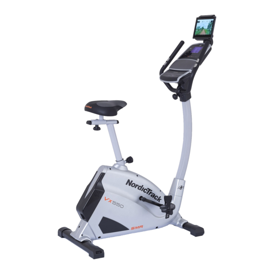
Model No. NTIVEX47016.0
Serial No.
Write the serial number in the space
above for reference.
Serial Number
Decal
CUSTOMER SERVICE
UNITED KINGDOM
Call: 0330 123 1045
From Ireland: 053 92 36102
Website: www.iconsupport.eu
E-mail: csuk@iconeurope.com
Write:
ICON Health & Fitness, Ltd.
Unit 1D, The Gateway
Fryers Way, Silkwood Park
OSSETT
WF5 9TJ
UNITED KINGDOM
CAUTION
Read all precautions and
instructions in this manual
before using this equipment.
Keep this manual for future
reference.
USER'S MANUAL
www.iconeurope.com
Advertisement
Table of Contents

Related Manuals for NordicTrack VX550


Summary of Contents for NordicTrack VX550
- Page 1 Model No. NTIVEX47016.0 USER’S MANUAL Serial No. Write the serial number in the space above for reference. Serial Number Decal CUSTOMER SERVICE UNITED KINGDOM Call: 0330 123 1045 From Ireland: 053 92 36102 Website: www.iconsupport.eu E-mail: csuk@iconeurope.com Write: ICON Health & Fitness, Ltd. Unit 1D, The Gateway Fryers Way, Silkwood Park OSSETT...
-
Page 2: Table Of Contents
TABLE OF CONTENTS WARNING DECAL PLACEMENT..............2 IMPORTANT PRECAUTIONS . -
Page 3: Important Precautions
IMPORTANT PRECAUTIONS WARNING : To reduce the risk of serious injury, read all important precautions and instructions in this manual and all warnings on your bike before using your bike. ICON assumes no responsibility for personal injury or property damage sustained by or through the use of this product. -
Page 4: Before You Begin
VX550 number before contacting us. The model number and the ® bike. The VX550 bike provides a selection of features location of the serial number decal are shown on the front designed to make your workouts at home more effective cover of this manual. -
Page 5: Part Identification Chart
PART IDENTIFICATION CHART Use the drawings below to identify the small parts needed for assembly. The number below each drawing is the key number of the part, from the PART LIST near the end of this manual. The number following the key number is the quan- tity needed for assembly. -
Page 6: Assembly
ASSEMBLY • Assembly requires two persons. of the part, from the PART LIST near the end of this manual. The number following the parentheses is • Place all parts in a cleared area and remove the the quantity needed for assembly. packing materials. - Page 7 STEP 1 Attach the front stabilizer (74) to the main frame (49) with the Carriage bolts (53), then fix the rear stabilizer (52) to the main frame (49) with the Carriage bolts (53) as shown. STEP 2 Attach the pedals (36L/R) to the cranks (39L/R) respectively, viewed from the rider’s exercising position.
- Page 8 STEP 4 A.Inset the Seat (31) to the post of Seat Gliding Set (30) and then fix it with Carriage Bolt ( 32), Springs ( 29) and Nuts ( 28). B.Fix the Seat Gliding Set (30) to the Seat Post (26) with Knob (34) and Washer (33). Note: Keep the Seat (31) tightly on to the post of Seat Gliding Set (30).
- Page 9 STEP 5 Put the Upper Computer Cable (6) through the hole of Handlebar Post and then out of the top. Fix the Handlebar (9) onto the Handlebar post with Knob (14) and Tube (13) after adjusting the Handlebar to a suitable position. STEP 6 Connect the Upper Computer Cable (6) and Handle Pulse Cable (12) onto the Computer (1).
-
Page 10: How To Use The Elliptical
HOW TO USE THE EXERCISE BIKE HOW TO ADJUST THE HEIGHT OF THE SEAT HOW TO LEVEL THE EXERCISE BIKE For effective exercise, the seat should be at the proper If the exercise bike rocks height. As you pedal, there should be a slight bend in your slightly on your floor during knees when the pedals are in the lowest position. -
Page 11: Console Features
CONSOLE FEATURES Contacts FEATURES OF THE CONSOLE The advanced console offers an array of features designed to make your workouts more effective and enjoyable. When you use the manual mode of the console, you can change the resistance of the pedals with the touch of a button. - Page 12 HOW TO USE THE MANUAL MODE Resistance—This display will show the resistance level of the pedals for a few seconds each time the resistance level changes. 1. Begin pedaling or press any button on the console to turn on the console. RPM—This display will show your pedaling speed in revolutions per minute (rpm).
- Page 13 3. Begin pedaling to start the workout. If there are sheets of plastic on the metal contacts on the handgrip heart Each workout is divided into one-minute seg- Contacts rate monitor, remove the ments. One resistance level and one target speed is plastic.
- Page 14 HOW TO USE THE SOUND SYSTEM 1. Download and install the iFit app on your smart device. To play music or audio books through the console sound system while you exercise, plug a 3.5 mm male to 3.5 mm On your iOS or Android™...
-
Page 15: Maintenance And Troubleshooting
increase and decrease buttons to adjust the contrast 4. Exit the settings mode. level. Usage Information—The display will show the total Press the Settings button to exit the settings mode. number of hours that the elliptical has been used and the total distance (in miles or kilometers) that has been pedaled on the elliptical. -
Page 16: Exercise Guidelines
EXERCISE GUIDELINES Burning Fat—To burn fat effectively, you must exercise at a low intensity level for a sustained period of time. During WARNING: Before beginning this the first few minutes of exercise, your body uses carbohy- or any exercise program, consult your physician. drate calories for energy. -
Page 17: Suggested Stretches
SUGGESTED STRETCHES The correct form for several basic stretches is shown at the right. Move slowly as you stretch— never bounce. 1. Toe Touch Stretch Stand with your knees bent slightly and slowly bend forward from your hips. Allow your back and shoulders to relax as you reach down toward your toes as far as possible. -
Page 18: Part List
PART LIST MODEL Key No. Qty. Description Key No. Qty. Description Computer Crank L Tablet Holder Crank R Screw M4-0.7*15 Plastic Screw Self-tapping Screw M4*16 Plastic Cover Computer Rack Chain Cover L Upper Computer Cable1000mm Chain Cover R Screw M4-0.7*15 Drill Screw M5*15 End Cap Φ25 C-Sharp Clip Φ15... -
Page 19: Exploded Drawing
EXPLODED DRAWING 24 23 22 21 70 71... -
Page 20: Ordering Replacement Parts
ORDERING REPLACEMENT PARTS To order replacement parts, please see the front cover of this manual. To help us assist you, be prepared to provide the following information when contacting us: • the model number and serial number of the product (see the front cover of this manual) •...