Advertisement
Model No. NTEVEX76017.0
Serial No.
USER'S MANUAL
Write the serial number in the space
above for reference.
Serial Number
Decal
CUSTOMER SERVICE
UNITED KINGDOM
Call: 0330 123 1045
From Ireland: 053 92 36102
Website: iconsupport.eu
E-mail: csuk@iconeurope.com
Write:
ICON Health & Fitness, Ltd.
Unit 4, Westgate Court
Silkwood Park
OSSETT
WF5 9TT
UNITED KINGDOM
AUSTRALIA
Call: 1800 993 770
E-mail: australiacc@iconfitness.com
Write:
ICON Health & Fitness
PO Box 635
WINSTON HILLS NSW 2153
AUSTRALIA
CAUTION
Read all precautions and
instructions in this manual before
using this equipment. Keep this
manual for future reference.
iconeurope.com
Advertisement
Table of Contents

Related Manuals for NordicTrack NTEVEX76017.0

Summary of Contents for NordicTrack NTEVEX76017.0
- Page 1 Model No. NTEVEX76017.0 Serial No. USER’S MANUAL Write the serial number in the space above for reference. Serial Number Decal CUSTOMER SERVICE UNITED KINGDOM Call: 0330 123 1045 From Ireland: 053 92 36102 Website: iconsupport.eu E-mail: csuk@iconeurope.com Write: ICON Health & Fitness, Ltd.
- Page 2 NORDICTRACK and IFIT are registered trademarks of ICON Health & Fitness, Inc. App Store is a trademark of Apple Inc., registered in the U.S. and other countries. Android and Google Play are trademarks of Google Inc. The BLUETOOTH word mark and logos are registered trademarks of Bluetooth SIG, Inc.
-
Page 3: Important Precautions
IMPORTANT PRECAUTIONS WARNING: To reduce the risk of serious injury, read all important precautions and instructions in this manual and all warnings on your exercise bike before using your exercise bike. ICON assumes no responsibility for personal injury or property damage sustained by or through the use of this product. -
Page 4: Before You Begin
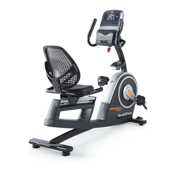
BEFORE YOU BEGIN Thank you for selecting the new NORDICTRACK reading this manual, please see the front cover of this ® COMMERCIAL VR 21 exercise bike. Cycling is an manual. To help us assist you, note the product model effective exercise for increasing cardiovascular fit- number and serial number before contacting us. -
Page 5: Part Identification Chart
PART IDENTIFICATION CHART Use the drawings below to identify the small parts needed for assembly. The number in parentheses below each drawing is the key number of the part, from the PART LIST near the end of this manual. The number following the key number is the quantity needed for assembly. -
Page 6: Assembly
ASSEMBLY • Assembly requires two persons. In addition to the included tool(s), assembly requires the following tools: • Place all parts in a cleared area and remove the one Phillips screwdriver packing materials. Do not dispose of the packing materials until you finish all assembly steps. one adjustable wrench •... - Page 7 3. With the help of a second person, place some of the packing materials (not shown) under the rear of the Frame (1). Attach the Rear Stabilizer (3) to the Frame (1) with two M10 x 120mm Screws (44); start both Screws, and then tighten them.
- Page 8 6. Attach the Accessory Tray (9) to the Upright (4) with an M6 x 50mm Screw (42). 7. Untie and discard the wire tie on the Main Wire (41). While a second person holds the Console Bracket (82) near the Upright (4), route the Main Wire (41) through the notch in the Upright, through the Upright Bracket (84), and through the hole in the center of the Console Bracket.
- Page 9 9. While a second person holds the Console (5) near the Console Bracket (82), connect the wires on the Console to the Main Wire (41) and to the Left and Right Pulse Wires (7, 8). Insert the excess wire into the Console Bracket (82).
- Page 10 11. Attach the Seat Handlebar (18) to the Seat Carriage (11) with four M8 x 40mm Screws (56); start all the Screws, and then tighten them. 12. Slide the Backrest Frame (14) onto the Seat Handlebar (18). Attach the Backrest Frame (14) with four M6 x 30mm Screws (51) and four M6 Washers (112);...
- Page 11 13. Attach the Seat (12) to the Seat Handlebar (18) with four M6 x 20mm Screws (67) and four M6 Washers (112) (only two of each are shown); start all the Screws, and then tighten them. 14. Identify the Right Pedal (29). Using an adjustable wrench, firmly tighten the Right Pedal (29) clockwise into the Right Crank Arm (99).
- Page 12 15. Plug the Power Adapter (107) into the receptacle on the frame of the exercise bike. Note: To plug the Power Adapter (107) into an outlet, see HOW TO PLUG IN THE POWER ADAPTER on page 13. 16. After the exercise bike is assembled, inspect it to make sure that it is assembled correctly and that it functions properly.
-
Page 13: How To Use The Exercise Bike
HOW TO USE THE EXERCISE BIKE HOW TO PLUG IN THE POWER ADAPTER HOW TO ADJUST THE SEAT IMPORTANT: If the exercise bike has been exposed The seat can be to cold temperatures, allow it to warm to room adjusted forward temperature before you plug in the power adapter. - Page 14 CONSOLE DIAGRAM FEATURES OF THE CONSOLE The advanced console offers an array of features designed to make your workouts more effective and enjoyable. When you use the manual mode of the console, you can change the resistance of the pedals with the touch of a button.
- Page 15 HOW TO USE THE MANUAL MODE Calories per Hour (Cals/Hr)—This display will show the approximate number of calories you are 1. Turn on the console. burning per hour. Distance—This display will show the distance that Begin pedaling or press any button on the console to turn on the console.
- Page 16 Scan Mode and Priority palms resting against the contacts. Avoid moving Mode—The calories and watts your hands or gripping the contacts tightly. displays will appear in an alternating cycle (scan mode). When your pulse is detected, your heart rate will appear in the display.
- Page 17 HOW TO USE AN ONBOARD WORKOUT next segment, the resistance level and/or target speed will appear in the display to alert you. The 1. Turn on the console. resistance of the pedals will then change. Begin pedaling or press any button on the console As you exercise, keep your pedaling speed near to turn on the console.
- Page 18 HOW TO USE THE WATTS WORKOUT If your watts output is too far below or above the target watts setting, the resistance of the pedals 1. Turn on the console. will automatically increase or decrease to bring your watts output closer to the target watts setting. Begin pedaling or press any button on the console to turn on the console.
- Page 19 HOW TO CONNECT YOUR TABLET TO THE 4. Record and track your workout information. CONSOLE Follow the instructions in the iFit Bluetooth Tablet The console supports BLUETOOTH connections to app to record and track your workout information. tablets via the iFit Bluetooth Tablet app and to compat- ible heart rate monitors.
- Page 20 HOW TO USE THE SOUND SYSTEM HOW TO CHANGE CONSOLE SETTINGS To play music or audio books through the console 1. Select the settings mode. sound system while you exercise, plug a 3.5 mm male to 3.5 mm male audio cable (not included) into the To select the settings mode, press the Settings jack on the console and into a jack on your personal button.
-
Page 21: Maintenance And Troubleshooting
MAINTENANCE AND TROUBLESHOOTING MAINTENANCE HOW TO ADJUST THE DRIVE BELT Regular maintenance is important for optimal If the pedals slip while you are pedaling, even while the performance and to reduce wear. Inspect and properly resistance is adjusted to the highest setting, the drive belt may need to be adjusted. - Page 22 HOW TO ADJUST THE REED SWITCH Locate the Reed Switch (35). Rotate the Left Crank Arm (100) until a Magnet (39) is aligned with the Reed If the console does not display correct feedback, the Switch. Next, loosen the Clamp Screw (A), slide the reed switch should be adjusted.
-
Page 23: Exercise Guidelines
EXERCISE GUIDELINES Burning Fat—To burn fat effectively, you must exer- WARNING: cise at a low intensity level for a sustained period of Before beginning this time. During the first few minutes of exercise, your or any exercise program, consult your physi- body uses carbohydrate calories for energy. -
Page 24: Part List
PART LIST Model No. NTEVEX76017.0 R0517A Key No. Qty. Description Key No. Qty. Description Frame M10-1.0 Flange Nut Front Stabilizer M6 x 30mm Screw Rear Stabilizer M4 x 25mm Screw Upright M5 x 20mm Screw Console M10 x 55mm Screw... - Page 25 Key No. Qty. Description Key No. Qty. Description Right Crank Arm M8 Split Washer Left Crank Arm Front Stabilizer Cap M10 x 60mm Bolt M10 x 96mm Screw M8 Locknut M4 x 30mm Screw M6 x 15mm Screw M6 Washer Crank Snap Ring M8 Hex Nut Crank...
-
Page 26: Exploded Drawing
EXPLODED DRAWING A Model No. NTEVEX76017.0 R0517A... - Page 27 EXPLODED DRAWING B Model No. NTEVEX76017.0 R0517A...
-
Page 28: Ordering Replacement Parts
ORDERING REPLACEMENT PARTS To order replacement parts, please see the front cover of this manual. To help us assist you, be prepared to provide the following information when contacting us: • the model number and serial number of the product (see the front cover of this manual) •...