Advertisement
Table of Contents
- 1 Table of Contents
- 2 Warning Decal Placement
- 3 Important Precautions
- 4 Before You Begin
- 5 Part Identification Chart
- 6 Assembly
- 7 The Chest Heart Rate Monitor
- 8 How to Use the Exercise Bike
- 9 Fcc Information
- 10 Maintenance and Troubleshooting
- 11 Exercise Guidelines
- 12 Part List
- 13 Exploded Drawing
- 14 Ordering Replacement Parts
- 15 Limited Warranty
- Download this manual
www.nordictrack.com
Model No. NTEX89914.0
Serial No.
Write the serial number in the
space above for reference.
Serial Number
Decal
ACTIVATE YOUR
WARRANTY
To register your product and
activate your warranty today, go
to www.nordictrackservice.com/
registration.
CUSTOMER CARE
For service at any time, go to
www.nordictrackservice.com.
Or call 1-800-TO-BE-FIT
(1-800-862-3348)
Mon.–Fri. 6 a.m.–6 p.m. MT
Sat. 8 a.m.–12 p.m. MT
Please do not contact the store.
CAUTION
Read all precautions and instruc-
tions in this manual before using
this equipment. Keep this manual
for future reference.
USER'S MANUAL
Advertisement
Table of Contents

Related Manuals for NordicTrack Commercial VR25 Elite


Summary of Contents for NordicTrack Commercial VR25 Elite
- Page 1 Model No. NTEX89914.0 Serial No. USER’S MANUAL Write the serial number in the space above for reference. Serial Number Decal ACTIVATE YOUR WARRANTY To register your product and activate your warranty today, go to www.nordictrackservice.com/ registration. CUSTOMER CARE For service at any time, go to www.nordictrackservice.com.
-
Page 2: Table Of Contents
Note: The decal(s) may not be shown at actual size. NORDICTRACK is a registered trademark of ICON Health & Fitness, Inc. IFIT is a registered trademark of ICON Health & Fitness, Inc. Google Maps is a trademark of Google Inc. -
Page 3: Important Precautions
IMPORTANT PRECAUTIONS WARNING: To reduce the risk of serious injury, read all important precautions and instructions in this manual and all warnings on your exercise bike before using your exercise bike. ICON assumes no responsibility for personal injury or property damage sustained by or through the use of this product. - Page 5 STANDARD SERVICE PLANS...
-
Page 6: Before You Begin
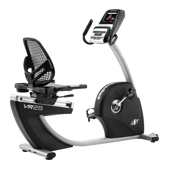
BEFORE YOU BEGIN Thank you for selecting the revolutionary reading this manual, please see the front cover of this NORDICTRACK COMMERCIAL VR 25 ELITE exer- manual. To help us assist you, note the product model ® cise bike. Cycling is an effective exercise for increasing number and serial number before contacting us. -
Page 7: Part Identification Chart
PART IDENTIFICATION CHART Use the drawings below to identify the small parts needed for assembly. The number in parentheses below each drawing is the key number of the part, from the PART LIST near the end of this manual. The number following the key number is the quantity needed for assembly. -
Page 8: Assembly
ASSEMBLY • Assembly requires two persons. In addition to the included tool(s), assembly requires the following tools: • Place all parts in a cleared area and remove the one Phillips screwdriver packing materials. Do not dispose of the packing materials until you fi nish all assembly steps. one adjustable wrench •... - Page 9 3. Set a sturdy piece of packing material under the front of the Frame (1). Have a second person hold the Frame to prevent it from tipping while you complete this step. Orient the Front Stabilizer (15) as shown. Attach the Front Stabilizer to the Frame (1) with two M10 x 122mm Screws (65).
- Page 10 5. Tip: Avoid pinching the wires. Slide the Upright (2) onto the Frame (1). Attach the Upright (2) with four M10 x 62mm Screws (70); start all the Screws, and then tighten them. Avoid pinching the wires 6. Press the mount on the Front Shield (58) into the Frame (1).
- Page 11 7. Orient the Upright Cover (57) as shown. Hold the Upright Cover near the Upright (2), and insert the wires upward through the Upright Cover. Then, slide the Upright Cover (57) onto the Wire Tie Upright (2). Wires 8. Orient the Handlebar (7) as shown. While a second person holds the Handlebar near the Upright (2), insert the wires upward through the Wire Tie...
- Page 12 10. Tip: Avoid pinching the wires. Attach the Console (4) to the Handlebar (7) with four M4 x 16mm Screws (77); start all the Screws, and then tighten them. Avoid pinching the wires 11. Attach the Upright Cover (57) to the Handlebar (7) with two M4 x 16mm Screws (77).
- Page 13 13. Insert the Rail Rod (60) into the Rail (5), and tighten a Rod Cap (62) onto each end of the Rail Rod. 14. Press the mounts on the Rear Rail Cover (90) into the Rail (5). Then, plug the wire on the seat assembly fully into the Frame Pulse Receptacle (42) on the left side of the exercise bike.
- Page 14 15. Identify the Right Pedal (21). Using an adjustable wrench, firmly tighten the Right Pedal (21) clockwise into the Right Crank Arm (23). Firmly tighten the Left Pedal (not shown) counterclockwise into the Left Crank Arm (not shown). IMPORTANT: You must turn the Left Pedal counterclockwise to attach it.
- Page 15 17. IMPORTANT: Locate the serial number decal (not shown) in the literature pack included with the exercise bike. Place the serial num- ber decal on the Upright (2) in the indicated location below the general warning decal. Then, plug the Power Adapter (51) into the Serial receptacle on the frame of the exercise bike.
-
Page 16: The Chest Heart Rate Monitor
THE CHEST HEART RATE MONITOR HOW TO PUT ON THE HEART RATE MONITOR • Do not expose the heart rate monitor to direct sun- light for extended periods of time; do not expose it to The heart rate monitor consists of a chest strap and temperatures above 122°... -
Page 17: How To Use The Exercise Bike
HOW TO USE THE EXERCISE BIKE HOW TO PLUG IN THE POWER ADAPTER HOW TO ADJUST THE PEDAL STRAPS IMPORTANT: If the exercise bike has been exposed To adjust the pedal to cold temperatures, allow it to warm to room straps, fi... - Page 18 CONSOLE DIAGRAM MAKE YOUR FITNESS GOALS A REALITY WITH Upload your workout results to the iFit cloud IFIT.COM and track your accomplishments. With your new iFit-compatible fitness equipment, you can use an array of features on iFit.com to make your Set calorie, time, or distance goals for your fitness goals a reality: workouts.
- Page 19 FEATURES OF THE CONSOLE HOW TO ACTIVATE THE CONSOLE The advanced console offers an array of features The included power adapter must be used to oper- designed to make your workouts more effective and ate the exercise bike. See HOW TO PLUG IN THE enjoyable.
- Page 20 HOW TO USE THE TOUCH SCREEN 2. Check for firmware updates. The console features a tablet with a full-color touch First, see step 1 on page 26 and step 2 on page screen. The following information will help you become 28 and select the maintenance mode.
- Page 21 HOW TO USE THE MANUAL MODE If desired, keep your pedaling speed near the tar- get cadence. The target zone meter will prompt you 1. Touch the screen, press any button on the to increase, decrease, or maintain your pedaling console, or begin pedaling to turn on the speed.
- Page 22 When your pulse is detected, your heart rate HOW TO USE AN ONBOARD WORKOUT will be shown. For the most accurate heart rate reading, hold the contacts for at least 15 1. Touch the screen, press any button on the seconds.
- Page 23 As you exercise, keep your pedaling speed near To pause the workout, touch either the back button the target cadence for the current segment. The or the home button at the bottom of the screen. To target zone meter will prompt you to increase, continue the workout, touch the Resume button.
- Page 24 HOW TO USE A SET-A-GOAL WORKOUT If the resistance level for the current segment is too high or too low, you can manually override the 1. Touch the screen, press any button on the setting by pressing the Resistance buttons. If you console, or begin pedaling to turn on the press a Resistance button, you can then manu- console.
- Page 25 HOW TO USE AN IFIT WORKOUT For more information about the iFit workouts, please see www.iFit.com. Note: To use an iFit workout, you must have access to a wireless network (see HOW TO USE THE When you select an iFit workout, the screen will WIRELESS NETWORK MODE on page 29).
- Page 26 HOW TO USE THE EQUIPMENT SETTINGS MODE 5. Enable or disable the Internet browser. IMPORTANT: Some of the features described may To enable or disable the Internet browser, first not be enabled. Occasionally, a firmware update touch the Browser button. Next, touch the Enable may add new features or cause your console to checkbox or the Disable checkbox.
- Page 27 9. Select a language. 14. Select an update time. To select a language, touch the Language button To select a time for automatic console updates, and select the desired language. touch the Update Time button and select the desired time. Then, touch the back button on the 10.
- Page 28 HOW TO USE THE MAINTENANCE MODE 4. Calibrate the screen. IMPORTANT: Some of the features described may If the screen is not properly calibrated, it will be not be enabled. Occasionally, a firmware update difficult for you to touch the correct buttons on the may add new features or cause your console to screen.
- Page 29 HOW TO USE THE WIRELESS NETWORK MODE name (SSID). If your network has a password, you will also need to know the password. The console features a wireless network mode that allows you to set up a wireless network connection. An information box will ask if you want to connect to the wireless network.
- Page 30 HOW TO USE THE SOUND SYSTEM HOW TO USE THE INTERNET BROWSER To play music or audio books through the console Note: To use the Internet browser, you must have sound system while you exercise, plug a 3.5 mm male access to a wireless network including a wireless to 3.5 mm male audio cable (not included) into the jack router (802.11b/g/n) with SSID broadcast enabled (hid-...
-
Page 31: Fcc Information
FCC INFORMATION This equipment has been tested and found to comply with the limits for a Class B digital device, pursuant to Part 15 of the FCC Rules. These limits are designed to provide reasonable protection against harmful interference in a residential installation. This equipment generates, uses, and can radiate radio frequency energy and, if not installed and used in accordance with the instructions, may cause harmful interference to radio communications. -
Page 32: Maintenance And Troubleshooting
MAINTENANCE AND TROUBLESHOOTING MAINTENANCE Next, remove the M4 x 16mm Screw (77) from the Access Cover (40). Then, remove the Access Cover. Inspect and tighten all parts of the exercise bike regularly. Replace any worn parts immediately. Locate the Reed Switch (46). Turn the Left Crank Arm (24) until a Pulley Magnet (30) is aligned with the Reed To clean the exercise bike, use a damp cloth and a Switch. - Page 33 HOW TO ADJUST THE DRIVE BELT Next, loosen the M6 x 20mm Hex Screw (84). Tighten the M10 x 50mm Hex Screw (83) until the Drive Belt If the pedals slip while you are pedaling, even while the (47) is tight. When the Drive Belt is tight, tighten the resistance is adjusted to the highest setting, the drive M6 x 20mm Hex Screw.
-
Page 34: Exercise Guidelines
EXERCISE GUIDELINES Burning Fat—To burn fat effectively, you must exer- WARNING: cise at a low intensity level for a sustained period of Before beginning this time. During the first few minutes of exercise, your or any exercise program, consult your physi- body uses carbohydrate calories for energy. - Page 35 SUGGESTED STRETCHES The correct form for several basic stretches is shown at the right. Move slowly as you stretch; never bounce. 1. Toe Touch Stretch Stand with your knees bent slightly and slowly bend forward from your hips. Allow your back and shoulders to relax as you reach down toward your toes as far as possible.
-
Page 36: Part List
PART LIST Model No. NTEX89914.0 R0115B Key No. Qty. Description Key No. Qty. Description Frame Reed Switch/Wire Upright Drive Belt Foot Stabilizer Cap Console Left Handlebar Grip Rail Flange Screw Adjustment Bar Power Adapter Handlebar Shield Disc Backrest Tablet Holder Seat #8 x 13mm Screw Seat Handlebar/Wire... - Page 37 Key No. Qty. Description Key No. Qty. Description M8 Split Washer Clip Nut Crank Cap M6 Locknut Barrel Nut M6 x 65mm Bolt Tree Fastener Power Receptacle/Wire M10 Flange Nut Chest Heart Rate Monitor M6 Split Washer Chest Strap Right Rear Shield –...
-
Page 38: Exploded Drawing
EXPLODED DRAWING A Model No. NTEX89914.0 R0115B... - Page 39 EXPLODED DRAWING B Model No. NTEX89914.0 R0115B...
-
Page 40: Ordering Replacement Parts
ORDERING REPLACEMENT PARTS To order replacement parts, please see the front cover of this manual. To help us assist you, be prepared to provide the following information when contacting us: • the model number and serial number of the product (see the front cover of this manual) •...