Table of Contents

Related Manuals for Samson 4708-5352


Summary of Contents for Samson 4708-5352
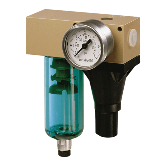
- Page 1 Supply Pressure Regulators Type 4708 Type 4708-5352 on Type 3730 Positioner Type 4708-1152 with filter receptacle Type 4708-6252 on Type 3372 Actuator Fig. 1 · Supply pressure regulators Mounting and Operating Instructions EB 8546 EN Edition June 2012...
-
Page 2: Table Of Contents
Contents Contents Page Design and principle of operation....4 Versions ....... . 6 Technical data . - Page 3 Safety instructions General safety instructions The supply pressure regulators may only be mounted, started up or serviced by fully trained and qualified personnel, observing the accepted industry codes and practices. Make sure employees or third persons are not exposed to any danger. All safety instructions and warnings in these mounting and operating instructions, particularly those concerning assembly, start-up and maintenance, must be observed.
-
Page 4: Design And Principle Of Operation
Design and principle of operation Design and principle of The compressed air at the inlet flows across the filter and through the free cross-sectional operation area between the seat (1.1) and plug (1.2). It leaves the outlet with a reduced pressure The supply pressure regulator is used to sup- depending on the plug position. - Page 5 Design and principle of operation Adapter plate/connecting plate Diverting gasket 1.2 1.3 10.1 11.1 12.1 Body Seat Plug Bore in body Operating diaphragm Venting bore Positioning spring Lock nut Set point screw Adjustment knob (accessories in Section 7) Filter cartridge Stopper Bushing 11.1 Gasket...
-
Page 6: Versions
Design and principle of operation Versions Supply pressure regulator with adapter plate for positioners Type 3730, 3766, 3767, 3780, Standard version Type 4708- 3785, 3787 Type 3730, 3766, 3767, 3780, Filter on aluminum basis without 3785, 3787 filter receptacle Type 4763/4765 With plastic filter receptacle Type 3760 With aluminum filter receptacle... -
Page 7: Technical Data
Design and principle of operation Technical data Supply pressure regulator Type 4708-xx 1 bar (15 psi) above the adjusted set point, Supply pressure however, at least 1.6 bar (24 psi) · Max. 12 bar (180 psi) Output pressure Adjustable from 0 to 1.6 bar (0 to 24 psi) or 0 to 6 bar (0 to 90 psi) Set point range 0.2 to 1.6 bar (3 to 24 psi) or 0.5 to 6 bar (8 to 90 psi) £... -
Page 8: Mounting The Supply Pressure Regulator
Mounting the supply pressure regulator Mounting the supply 2.1.1 Direction of flow pressure regulator In the compact supply pressure regulators 4708-10xx/-11xx/-14xx and -17xx the To prevent excessive amounts of condensed direction of flow can be changed as follows: water from collecting, the distance between the compressor and supply pressure regula- 1. -
Page 9: Turning The Supply Pressure Regulator
Mounting the supply pressure regulator 2.1.2 Turning the supply pressure 3. Turn the regulator 180 degrees and re- regulator insert the gasket. In this way, you keep the bore assignment of the gasket for The supply pressure regulator can be turned supply air input and regulator outlet. -
Page 10: Supply Pressure Regulators For Attachment To Positioners And Actuators
Mounting the supply pressure regulator Supply pressure regulators Type 4708-54xx has a second output sealed with a stopper. This is intended for for attachment to positioners reduced supply air. It can be used to supply and actuators a second device, if required (e.g. a pilot-op- erated solenoid valve). - Page 11 Mounting the supply pressure regulator Type 4708-55xx for Type 4763 and 6. Seal the spare connections with stoppers Type 4765 Positioner (4) to prevent dirt from entering the de- vice. 1. Screw the special nuts (5) into the con- necting holes of the positioner. 2.
- Page 12 Mounting the supply pressure regulator Type 4708-58xx for Type 3761 Positioner 1. Screw the special nut (5) into the SUPPLY connecting hole of the positioner. 2. Push the special hollow screw (6) into the connection hole of the adapter plate (1).
- Page 13 Mounting the supply pressure regulator Type 4708-62xx for Type 3372 Actuator 3. Insert the O-ring (9). Position the supply pressure regulator and fasten it onto ac- 1. Screw the special nut (5) into the SUPPLY tuator using the special screw. connecting hole of the actuator.
-
Page 14: Pneumatic Connections
Pneumatic connections Pneumatic connections Pressure gauge The pneumatic connections are designed ei- Mount the pressure gauge in such a way ther as G ¼ or ¼ NPT-18 threads. On com- that there is a 2-3 mm gap between the lock pact supply pressure regulators, an arrow nut and pressure gauge's square end after on the adhesive label indicates the direction... -
Page 15: Additional Connection For A Solenoid Valve
Pneumatic connections Additional connection for a The reduced supply pressure of the supply pressure regulator is additionally routed to solenoid valve the threaded connection at the side over the corresponding holes in the intermediate An additional output for reduced air pres- plate. - Page 16 Pneumatic connections Mounting the intermediate plate Note: The long rubber finger of the diverting gasket (3) must always point in the direction 1. Remove the fixing screws and lift the of the regulator outlet (reduced supply air). supply pressure regulator (4) together See Figs.
- Page 17 Pneumatic connections the adapter plate and the bores (1.1) for the fixing screws are aligned. 4. Place the supply pressure regulator (4) with the diverting gasket (3) onto the in- termediate plate (2). Insert the longer fix- ing screws and fasten the parts. SUPPLY Fig.
-
Page 18: Manual/Automatic Transfer
Pneumatic connections Manual/automatic transfer 3.3.1 Mounting on positioners The positioner output is routed to the actua- tor over the manual/automatic transfer. In automatic mode, the positioner is in closed-loop operation. In manual mode, the output pressure of any supply pressure regu- lator is directly applied to the actuator. -
Page 19: Mounting Using An Adapter Plate
Pneumatic connections 3.3.2 Mounting using an adapter Optionally, a Type 4708-53 Supply Pres- sure Regulator can be mounted upstream of plate the manual/automatic transfer unit (Fig. 15). Fasten adapter plate, for example to a NAMUR rib using a hexagon socket screw. -
Page 20: Operating The Manual/Automatic Transfer
Pneumatic connections 3.3.3 Operating the manual/ Filter with filter receptacle automatic transfer The Types 4708-83, 4708-84, 4708-86 and 4708-87 Air Filters are designed for In normal operation, the manual/automatic universal use. They have either G ¼ or transfer runs in automatic mode, during ¼-18 NPT threaded connections. -
Page 21: Rotatable Supplementary Filter
Pneumatic connections Rotatable supplementary 3.5.1 Mounting the rotatable filter supplementary filter The rotatable supplementary filter (see Remove the cover and filter cartridge Fig. 15) is designed for mounting to Type from the supply pressure regulator. 4708-53 and Types 4708-55 to -64 Supply Place the supplied seal carefully onto the Pressure Regulators. -
Page 22: Set Point Adjustment
Set point adjustment Set point adjustment Maintenance (Fig. 2) (Fig. 2) Depending on the version, the set point of We recommend you check the filter as often the supply pressure regulator can be ad- as possible. justed either at the adjustment knob (8), or Drain condensed water that has collected: after screwing off the cap (5), at the set Remove the stopper (10) or... -
Page 23: Troubleshooting
Troubleshooting Troubleshooting Leakage between supply pressure regu- lator and adapter plate: Check whether the diverting gasket (Figs. 3 and 4) is installed and both fix- ing screws are tightened properly. Excessive blow-off over the venting bore (3 in Fig. 2): Check whether the diverting gasket (Figs. -
Page 24: Accessories
Accessories Accessories Accessories Order no. Mounting parts for mounting on rail acc. to EN 50022 1400-7341 acc. to EN 50035 1400-7342 Mounting parts for mounting on bracket for Type 3271 or Type 3277 Actuator 1400-7343 Intermediate plate for additional connection with Types 4708-10xx/-11xx/-53xx/-55xx/-58xx/-62xx/-64xx (not required for Type 4708-54xx) Aluminum with G ¼... -
Page 25: Dimensions In Mm
Dimensions in mm Dimensions in mm Type 4708-11xx/14xx Supply Pressure Regulator Type 4708-10xx/17xx Supply Pressure Regulator 78 (102) 182 (206) Mounting bracket (accessories) Supply pressure regulators with intermediate plate The overall height increases by 24 mm for the additional connection. In this case, the dimensions in parentheses () apply. - Page 26 Dimensions in mm Type 4708-12xx/13xx Supply Pressure Regulator Type 4708-83xx/84xx/86xx/87xx Supply Pressure Regulator Ø41 Type 4708-53xx Supply Pressure Regulator for Types 3730/3766/3767/3780/3785/3787 Positioners Output 65(89) Supply EB 8546 EN...
- Page 27 Dimensions in mm Type 4708-54xx Supply Pressure Regulator for Types 3730/3766/3767/3780/3785/3787 Positioners Output Supply Output (reduced supply) Type 4708-55xx for Types 4763/4765 Positioners Output Supply 66 (90) EB 8546 EN...
- Page 28 Dimensions in mm Type 4708-57xx Supply Pressure Regulator for Type 3760 Positioner Input Signal Supply Supply Input Signal 133 (157) EB 8546 EN...
- Page 29 Dimensions in mm Type 4708-58xx for Type 3761 Positioner (84) Supply SAMSON Type 4708-64xx for Type 3277 Actuator Attachment on left or right Supply EB 8546 EN...
- Page 30 Dimensions in mm Type 4708-6221 for Type 3372-031x Actuator 111(135) Supply Supply Type 4708-82 Manual/automatic transfer unit with adapter plate EB 8546 EN...
- Page 31 EB 8546 EN...
- Page 32 SAMSON AG · MESS- UND REGELTECHNIK Weismüllerstraße 3 · 60314 Frankfurt am Main · Germany Phone: +49 69 4009-0 · Fax: +49 69 4009-1507 EB 8546 EN Internet: http://www.samson.de...