
Related Manuals for Yamaha Tmax XP500 2016


Summary of Contents for Yamaha Tmax XP500 2016
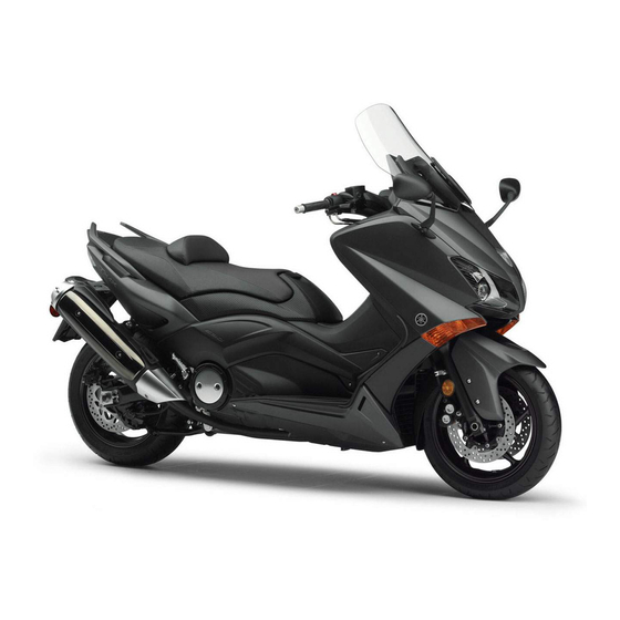
- Page 1 OWNER’S MANUAL XP500 MOTORCYCLE Read this manual carefully before oper- ating this vehicle. XP500 XP500A 2PW-28199-E1...
- Page 2 EAU72660 Read this manual carefully before operating this vehicle. This manual should stay with this vehicle if it is sold.
- Page 3 If you have any further questions, do not hesitate to con- tact your Yamaha dealer. The Yamaha team wishes you many safe and pleasant rides. So, remember to put safety first! Yamaha continually seeks advancements in product design and quality. There-...
-
Page 4: Important Manual Information
*Product and specifications are subject to change without notice. EAU10201 XP500/XP500A OWNER’S MANUAL ©2015 by Yamaha Motor Co., Ltd. 1st edition, August 2015 All rights reserved. Any reprinting or unauthorized use without the written permission of Yamaha Motor Co., Ltd. -
Page 5: Table Of Contents
Table of contents Safety information ......1-1 For your safety – pre-operation checks ..........5-1 Further safe-riding points ....1-5 Description ........2-1 Operation and important riding points..........6-1 Left view .......... 2-1 Right view........2-2 Starting the engine......6-2 Controls and instruments .... - Page 6 Table of contents Checking and lubricating the throttle grip and cable....7-25 Lubricating the front and rear brake levers........7-25 Checking and lubricating the centerstand and sidestand ..7-26 Checking the front fork ....7-26 Checking the steering....7-27 Checking the wheel bearings ..7-27 Battery ...........7-28 Replacing the fuses .......7-29 Headlights........7-31 Auxiliary lights........7-32...
-
Page 7: Safety Information
Safety information for a list of pre-operation checks. EAU1026B This scooter is designed to carry the operator and a passenger. Be a Responsible Owner The failure of motorists to detect As the vehicle’s owner, you are respon- and recognize scooters in traffic is sible for the safe and proper operation the predominating cause of auto- of your scooter. - Page 8 Safety information Protective Apparel help you to avoid an accident. • We recommend that you prac- The majority of fatalities from scooter tice riding your scooter where accidents are the result of head inju- ries. The use of a safety helmet is the there is no traffic until you have become thoroughly familiar with single most critical factor in the preven-...
- Page 9 Genuine senger, accessories and cargo must Yamaha accessories, which are avail- not exceed the maximum load limit. able only from a Yamaha dealer, have Operation of an overloaded vehicle been designed, tested, and approved could cause an accident.
- Page 10 Yamaha or should be kept to a minimum. modifications not specifically recom- • Bulky or large accessories may mended by Yamaha, even if sold and seriously affect the stability of installed by a Yamaha dealer. the scooter due to aerodynamic effects.
-
Page 11: Further Safe-Riding Points
Safety information Transporting the Scooter EAU57600 Further safe-riding points Be sure to observe following instruc- Be sure to signal clearly when tions before transporting the scooter in making turns. another vehicle. Braking can be extremely difficult Remove all loose items from the on a wet road. -
Page 12: Description
Description EAU63371 Left view 8 7 6 1. Battery (page 7-28) 2. Helmet holder (page 4-17) 3. Rear storage compartment (page 4-18) 4. Grab bar (page 6-3) 5. Engine oil filler cap (page 7-10) 6. Sidestand (page 4-22) 7. Engine oil drain bolt (page 7-10) 8. -
Page 13: Right View
Description EAU63391 Right view 1. Owner’s tool kit (page 7-2) 2. Fuel tank cap (page 4-14) 3. Air filter element (page 7-15) 4. Windshield (page 4-19) 5. Fuses (page 7-29) 6. Centerstand (page 7-26) -
Page 14: Controls And Instruments
Description EAU63401 Controls and instruments 1. Rear brake lever (page 4-12) 2. Left handlebar switches (page 4-10) 3. Rear brake lock lever (page 4-12) 4. Speedometer (page 4-2) 5. Multi-function display (page 4-3) 6. Tachometer (page 4-3) 7. Right handlebar switches (page 4-10) 8. -
Page 15: Smart Key System
Smart key system EAU61663 Smart key system The smart key system enables the ve- hicle to be operated without using a mechanical key. EWA14704 WARNING Keep implanted pacemakers or cardiac defibrillators, as well as other electric medical devices away from the vehicle mounted 1. -
Page 16: Operating Range Of The Smart Key
Smart key system EAU61582 Operating range of the smart key system The operating range of the smart key system is about 80 cm (31.5 in) from the center of the handlebars. 1. “SEAT OPEN/ ” switch 2. “OFF/LOCK” switch ECA15763 NOTICE The smart key system uses weak ra- dio waves. -
Page 17: Handling Of The Smart Key And Mechanical Key
Smart key system or cannot communicate with the EAU61643 Handling of the smart key and vehicle, all switches will be tempo- mechanical key rarily disabled. EWA17952 Placing the smart key in the front WARNING or rear storage compartment may The smart key should be carried ... - Page 18 Do not leave the smart key in a smart key system still does not operate, place exposed to direct sun- have a Yamaha dealer check the vehi- light, high temperature or high cle. humidity. Do not grind or attempt to mod-...
-
Page 19: Smart Key
Smart key system EAU61673 Smart key You can register up to six smart keys for the same vehicle. See a Yamaha dealer regarding spare smart keys. 1. “ON/OFF” switch 2. Smart key indicator light When the smart key is turned on and... -
Page 20: Replacing The Smart Key Battery
Smart key system EAU61603 Replacing the smart key battery Replace the battery in the following sit- uations. The smart key system indicator light flashes for about 20 seconds when the power of the vehicle is turned on. When the smart key indicator light 1. - Page 21 Smart key system damaged or contaminated by dirt. Dispose of the removed battery in ac- Do not touch the internal cir- cordance with local regulations. cuits and terminals. This may cause malfunctions. 5. Install a new battery as shown. Do not apply excessive force to Note the polarity of the battery.
-
Page 22: Vehicle Power On And Steering Lock Release
1. With the smart key on and in oper- and the smart key system indicator ating range, press the “ON/ ” light is flashing, have a Yamaha switch for one second. dealer check the smart key system. 3. The power of the vehicle is turned on once the steering lock is com- pletely released. -
Page 23: Powering Off The Vehicle
Smart key system Be sure to stop the vehicle in a EAU61693 Powering off the vehicle safe place when turning off the To turn the vehicle power off (and stop power. the engine if it is running), with the Without the smart key, the vehicle smart key on and within operating power can be turned off by press-... -
Page 24: How To Lock The Steering
Smart key system EAU61612 EAU61683 How to lock the steering Seat opening and closing After moving the vehicle to a safe park- To open the seat ing place, turn off the power of the vehi- cle. Turn the handlebars fully to the left 1. -
Page 25: Parking Mode
Smart key system EAU61593 Parking mode Make sure the seat is properly The steering is locked, and the hazard closed before starting off. lights and turn signal lights can be In case of an emergency, the seat turned on, but all other electrical sys- can be opened with a mechanical tems are off. -
Page 26: Instrument And Control Functions
Yamaha dealer check the electrical circuit. This warning light will come on when the vehicle power is on and the “ON/ ”... -
Page 27: Speedometer
When the start switch is pushed, the in- dicator light will come on for about one second and then go off. If the indicator light does not come on or go off as nor- mal, have a Yamaha dealer check the vehicle. -
Page 28: Tachometer
Instrument and control functions EAU63551 EAU63564 Tachometer Multi-function display EWA12313 WARNING Be sure to stop the vehicle before making any setting changes to the multi-function display. Changing settings while riding can distract the operator and increase the risk of an accident. - Page 29 Instrument and control functions Clock 1. Clock 1. Clock The multi-function display is equipped with the following: The clock uses a 24-hour time system. a fuel meter The clock displays when the key is a coolant temperature meter turned to “ON”.
- Page 30 Instrument and control functions the display between the odometer mode and the tripmeter modes in the following order: Odo Trip 1 Trip 2 V-Belt Trip Oil Trip Odo When approximately 3.0 L (0.79 US gal, 0.66 Imp.gal) of fuel remains in the fuel tank, the display will automatically change to the fuel reserve tripmeter mode “Trip F”...
- Page 31 Instrument and control functions been reset. ECA10022 NOTICE Do not continue to operate the en- Fuel meter gine if it is overheating. The fuel meter indicates the amount of fuel in the fuel tank. The display seg- Oil change indicator “Oil” ments of the fuel meter disappear to- wards “E”...
- Page 32 “V-Belt” onds and then goes off. 3. If the V-belt replacement indicator does not come on, have a Yamaha dealer check the electrical circuit. Ambient temperature display, aver- age fuel consumption, and instan- taneous fuel consumption modes 1.
- Page 33 Instrument and control functions For the UK: Average fuel consumption mode Push the “RESET” button to switch the display between the ambient tempera- ture display “Air”, the average fuel con- sumption mode “AVE_ _._ MPG” and the instantaneous fuel consumption mode “MPG”...
- Page 34 When the display is set to “km/L”, note the code number, and then have a the distance that can be traveled Yamaha dealer check the vehicle. on 1.0 L of fuel under the current ECA11591 NOTICE riding conditions is shown.
-
Page 35: Handlebar Switches
Instrument and control functions turn, push this switch to “ ”. When re- EAU1234H Handlebar switches leased, the switch returns to the center Left position. To cancel the turn signal lights, push the switch in after it has re- turned to the center position. EAU12501 Horn switch “... -
Page 36: Front Brake Lever
Instrument and control functions an emergency or to warn other drivers EAU44912 Front brake lever when your vehicle is stopped where it might be a traffic hazard. ECA10062 NOTICE Do not use the hazard lights for an extended length of time with the en- gine not running, otherwise the bat- tery may discharge. -
Page 37: Rear Brake Lever
Instrument and control functions EAU44922 EAU63230 Rear brake lever Rear brake lock lever 1. Rear brake lever 1. Rear brake lock lever 2. Brake lever position adjusting dial This vehicle is equipped with a rear 3. “ ” mark brake lock lever to prevent the rear 4. -
Page 38: Abs (For Abs Models)
ABS is operating. However, EAU63591 ABS (for ABS models) special tools are required, so The Yamaha ABS (Anti-lock Brake please consult your Yamaha deal- System) features a dual electronic con- trol system, which acts on the front and ECA20100 rear brakes independently. -
Page 39: Fuel Tank Cap
Instrument and control functions EAU63691 Fuel tank cap To remove the fuel tank cap 1. Open the lid by pulling the lever up. 1. Match marks 2. Turn the key counterclockwise to the original position, and then re- move it. 3. -
Page 40: Fuel
Your Yamaha engine has been de- 1. Fuel tank filler tube signed to use regular unleaded gaso- 2. Maximum fuel level line with a research octane number of 3. -
Page 41: Catalytic Converter
10% (E10). Gas- possible fire hazards such as ohol containing methanol grass or other materials that recommended by Yamaha because it easily burn. can cause damage to the fuel system Park the vehicle in a place or vehicle performance problems. -
Page 42: Adjusting The Rider Backrest
Instrument and control functions EAU63600 EAU63640 Adjusting the rider backrest Helmet holder The rider backrest can be adjusted to the three different positions shown. 1. Shaded projection 2. Helmet holding cable 3. Helmet holder 1. Rider backrest The helmet holder is located under the Adjust the backrest as follows. -
Page 43: Storage Compartments
Instrument and control functions Rear storage compartment EAU63510 Storage compartments A helmet can be stored in the rear stor- age compartment under the seat. (See Front storage compartment page 3-10 for seat opening and closing To open the storage compartment information.) To store a helmet in the when it is locked, insert the mechanical rear storage compartment, place the... -
Page 44: Windshield
Instrument and control functions locked inside and the smart key EAU52212 Windshield system may not operate normally. To suit the rider’s preference, the wind- ECA15963 shield height can be changed to one of NOTICE two positions. Do not leave the seat open for ... - Page 45 Instrument and control functions 1. Screw 1. Screw 3. Remove the rubber caps. 6. Tighten the screws to the specified torque. WARNING! A loose wind- shield could cause an accident. Be sure to tighten the screws to the specified torque. [EWA15511] Tightening torque: Windshield screw:...
-
Page 46: Rear View Mirrors
Be sure to fold the rear view mirrors Do not dispose of a damaged or back to their original position before worn-out shock absorber as- riding. sembly yourself. Take the shock absorber assembly to a Yamaha dealer for any service. 4-21... -
Page 47: Sidestand
Therefore, check this system regularly and have a Yamaha dealer repair it if it does not function properly. 4-22... - Page 48 • If a malfunction is noted, have a 3. Turn the vehicle power on. Yamaha dealer check the system 4. Keep the front or rear brake applied. before riding. 5. Push the “ON/ ”...
-
Page 49: Auxiliary Dc Jack
Instrument and control functions EAU49453 Auxiliary DC jack EWA14361 WARNING To prevent electrical shock or short- circuiting, make sure that the cap is installed when the auxiliary DC jack is not being used. ECA15432 NOTICE 1. Auxiliary DC jack The accessory connected to the 5. -
Page 50: For Your Safety - Pre-Operation Checks
Do not operate the vehicle if you find any problem. If a problem cannot be corrected by the procedures provided in this manual, have the vehicle inspected by a Yamaha dealer. Before using this vehicle, check the following points:... - Page 51 • Tighten if necessary. Instruments, lights, • Check operation. — signals and switches • Correct if necessary. • Check operation of ignition circuit cut-off system. Sidestand switch • If system is not working correctly, have Yamaha dealer 4-22 check vehicle.
-
Page 52: Operation And Important Riding Points
This model is equipped with: there is a control or function you do not a lean angle sensor to stop the en- understand, ask your Yamaha dealer. gine in case of a turnover. In this EWA10272 case, the display will indicate error... -
Page 53: Starting The Engine
Operation and important riding points EAU61552 ECA21980 Starting the engine NOTICE ECA10251 If the engine warning light or the NOTICE warning light (for ABS- See page 6-5 for engine break-in in- equipped models) does not come on structions prior to operating the ve- and then go off as explained above, hicle for the first time. -
Page 54: Starting Off
Operation and important riding points EAU45093 EAU16782 Starting off Acceleration and deceleration 1. While pulling the rear brake lever with your left hand and holding the grab bar with your right hand, push the scooter off the centerstand. The speed can be adjusted by opening and closing the throttle. -
Page 55: Braking
Operation and important riding points Rear EAU16794 Braking EWA10301 WARNING Avoid braking hard or suddenly (especially when leaning over to one side), otherwise the scooter may skid or overturn. Railroad crossings, streetcar rails, iron plates on road con- struction sites, and manhole covers become extremely slip- pery when wet. -
Page 56: Tips For Reducing Fuel Consumption
The vehicle can now be operated nor- mally. ECA10311 NOTICE Keep the engine speed out of the tachometer red zone. If any engine trouble should oc- cur during the engine break-in period, immediately have a Yamaha dealer check the vehi- cle. -
Page 57: Parking
Operation and important riding points EAU63740 Parking When parking, turn the vehicle power off, and then turn the smart key off. EWA10312 WARNING Since the engine and exhaust system can become very hot, park in a place where pedestri- ans or children are not likely to touch them and be burned. -
Page 58: Periodic Maintenance And Adjustment
If you are not familiar with vehicle ser- vice, have a Yamaha dealer perform service. EWA15123 WARNING Turn off the engine when performing... -
Page 59: Owner's Tool Kit
If you do not have the tools or experi- ence required for a particular job, have a Yamaha dealer perform it for you. -
Page 60: Periodic Maintenance Chart For The Emission Control System
From 50000 km (30000 mi), repeat the maintenance intervals starting from 10000 km (6000 mi). Items marked with an asterisk should be performed by a Yamaha dealer as they require special tools, data and technical skills. EAU63321 Periodic maintenance chart for the emission control system... -
Page 61: General Maintenance And Lubrication Chart
Periodic maintenance and adjustment EAU64031 General maintenance and lubrication chart ODOMETER CHECK OR READINGS MAINTENANCE JOB ITEM X 1000 km X 1000 mi Air filter element • Replace. • Clean. V-belt case air filter elements ... - Page 62 Periodic maintenance and adjustment ODOMETER CHECK OR READINGS MAINTENANCE JOB ITEM X 1000 km X 1000 mi Drive pulley and 13 * • Lubricate. drive axle • Check bearing play and steering for roughness. 14 * Steering bearings •...
- Page 63 Periodic maintenance and adjustment ODOMETER CHECK OR READINGS MAINTENANCE JOB ITEM X 1000 km X 1000 mi Moving parts and • Lubricate. cables • Check operation. • Check throttle grip free play, 28 * Throttle grip ...
-
Page 64: Removing And Installing Panels
Periodic maintenance and adjustment EAU18773 Removing and installing panels The panels shown need to be removed to perform some of the maintenance jobs described in this chapter. Refer to this section each time a panel needs to be removed and installed. 1. - Page 65 Periodic maintenance and adjustment 3. Remove the panel as shown. 3. Install the quick fastener. Panel C To remove the panel Remove the screws, and then pull the panel backward and upward. To install the panel 1. Insert the tabs on the upper left and right sides of the panel.
-
Page 66: Checking The Spark Plugs
Do not attempt to diagnose such problems yourself. Instead, have a Yamaha dealer check the vehicle. If a spark plug shows signs of electrode erosion and excessive carbon or other deposits, it should be replaced. -
Page 67: Engine Oil And Oil Filter Cartridge
Periodic maintenance and adjustment EAU1985E Engine oil and oil filter cartridge The engine oil level should be checked before each ride. In addition, the oil must be changed and the oil filter car- tridge replaced at the intervals speci- fied in the periodic maintenance and lubrication chart. - Page 68 Periodic maintenance and adjustment 1. Engine oil level check window 1. Engine oil drain bolt 2. Maximum level mark 2. O-ring 3. Minimum level mark 3. Gasket 4. If the engine oil is below the mini- 5. Check the O-ring for damage and mum level mark, add sufficient oil replace it if necessary.
- Page 69 Oil filter cartridge: 17 Nm (1.7 m·kgf, 12 ft·lbf) An oil filter wrench is available at a Yamaha dealer. 9. Install the engine oil drain bolt and its new gasket, and then tighten 7. Apply a thin coat of clean engine the bolt to the specified torque.
-
Page 70: Coolant
Periodic maintenance and adjustment lubricates the clutch), do not EAU20071 Coolant mix any chemical additives. Do The coolant level should be checked not use oils with a diesel speci- before each ride. In addition, the cool- fication of “CD” or oils of a high- ant must be changed at the intervals er quality than specified. - Page 71 Periodic maintenance and adjustment corrosion. If water has been added to the coolant, have a Yamaha dealer check the anti- freeze content of the coolant as soon as possible, otherwise the effectiveness of the coolant will be reduced. [ECA10473] 1. Floorboard mat 4.
-
Page 72: Replacing The Air Filter Element
Periodic maintenance and adjustment element installed, otherwise the EAU52031 Replacing the air filter element piston(s) and/or cylinder(s) may The air filter element should be re- become excessively worn. [ECA10482] placed at the intervals specified in the 5. Install the air filter case cover by in- periodic maintenance and lubrication stalling the screws. -
Page 73: Adjusting The Engine Idling Speed
(a). To decrease the en- gine idling speed, turn the screw in 3.0–5.0 mm (0.12–0.20 in) direction (b). Periodically check the throttle grip free play and, if necessary, have a Yamaha dealer adjust it. 1. Idle adjusting screw Engine idling speed: 1100–1300 r/min... -
Page 74: Valve Clearance
Therefore, it must be adjusted by a Yamaha dealer is essential to maintain the tires in good at the intervals specified in the periodic condition at all times and replace them maintenance and lubrication chart. - Page 75 Old and aged tires shall be glass fragments in it, or if the sidewall is checked by tire specialists to ascertain cracked, have a Yamaha dealer re- their suitability for further use. place the tire immediately. 7-18...
-
Page 76: Cast Wheels
If any Always make sure that the valve damage is found, have a Yamaha caps are securely installed to dealer replace the wheel. Do not prevent air pressure leakage. attempt even the smallest repair to Use only the tire valves and ... -
Page 77: Checking The Front And Rear Brake Lever Free Play
Rear 1. No brake lever free play There should be no free play at the brake lever ends. If there is free play, have a Yamaha dealer inspect the brake system. EWA14212 WARNING A soft or spongy feeling in the brake lever can indicate the presence of air in the hydraulic system. -
Page 78: Adjusting The Rear Brake Lock Cable
(b). WARNING! If proper adjustment cannot be obtained as described, 1. Wear indicator groove have a Yamaha dealer make this ad- 2. Wear indicator justment. [EWA16151] 3. Rubber boot... -
Page 79: Checking The Front And Rear Brake Pads
Insufficient brake fluid may al- have a Yamaha dealer replace the low air to enter the brake sys- brake pads as a set. tem, reducing braking performance. -
Page 80: Changing The Brake Fluid
Clean the filler cap before re- EAU22733 Changing the brake fluid moving. Use only DOT 4 brake Have a Yamaha dealer change the fluid from a sealed container. brake fluid at the intervals specified in Use only the specified brake flu- ... -
Page 81: Drive Belt Slack
Drive belt slack Checking and lubricating the cables The drive belt slack should be checked and adjusted by a Yamaha dealer at The operation of all control cables and the intervals specified in the periodic the condition of the cables should be maintenance and lubrication chart. -
Page 82: Checking And Lubricating The Throttle Grip And Cable
Front brake lever be checked before each ride. In addi- tion, the cable should be lubricated by a Yamaha dealer at the intervals speci- fied in the periodic maintenance chart. The throttle cable is equipped with a rubber cover. Make sure that the cover is securely installed. -
Page 83: Checking The Front Fork
EWA10742 WARNING If the centerstand or sidestand does not move up and down smoothly, have a Yamaha dealer check or re- pair it. Otherwise, the centerstand or ECA10591 sidestand could contact the ground NOTICE and distract the operator, resulting If any damage is found or the front in a possible loss of control. -
Page 84: Checking The Steering
If there is play in the wheel ward and backward. If any free hub or if the wheel does not turn play can be felt, have a Yamaha smoothly, have a Yamaha dealer check dealer check or repair the steering. -
Page 85: Battery
IES OUT OF THE REACH OF CHILDREN. To charge the battery 1. Negative battery lead (black) Have a Yamaha dealer charge the bat- 2. Positive battery lead (red) tery as soon as possible if it seems to 3. Battery have discharged. Keep in mind that the... -
Page 86: Replacing The Fuses
Periodic maintenance and adjustment ing the battery, connect the EAU54025 Replacing the fuses positive lead before connecting The main fuse box and the fuse box, the negative lead. [ECA21910] which contains the fuses for the individ- 4. After installation, make sure that ual circuits, are located under panel B. - Page 87 Periodic maintenance and adjustment For XP500 For XP500A 1. Signaling system fuse 1. Spare fuse 2. Ignition fuse 2. ABS solenoid fuse 3. Parking lighting fuse 3. ABS motor fuse 4. Radiator fan motor fuse 4. Headlight fuse 5. Fuel injection system fuse 5.
-
Page 88: Headlights
Headlights check the electrical system. This model is equipped with LED-type headlights. If a headlight does not come on, have a Yamaha dealer check its electrical cir- cuit. ECA16581 NOTICE Do not affix any type of tinted film or stickers to the headlight lens. -
Page 89: Auxiliary Lights
This model is equipped with an LED- auxiliary lights. type tail/brake light. If an auxiliary light does not come on, If the tail/brake light does not come on, have a Yamaha dealer check it. have a Yamaha dealer check it. 7-32... -
Page 90: Replacing A Front Turn Signal Light Bulb
Replacing a front turn signal Rear turn signal light bulb light bulb If a rear turn signal light does not come on, have a Yamaha dealer check the 1. Place the scooter on the center- electrical circuit or replace the bulb. stand. -
Page 91: Replacing The License Plate Light Bulb
The following troubleshooting charts represent quick and easy procedures for checking these vital systems your- self. However, should your scooter re- quire any repair, take it to a Yamaha dealer, whose skilled technicians have 1. Screw the necessary tools, experience, and know-how to service the scooter prop- 2. - Page 92 (See page 7-28.) If the smart key system does not work after checking the above-mentioned items, have a Yamaha dealer check the smart key system. Refer to emergency mode on page 7-38 on how to start the engine without using the smart key.
-
Page 93: Troubleshooting Charts
Check the vehicle. compression. 4. Compression The engine does not start. There is compression. Have a Yamaha dealer check the vehicle. Operate the electric starter. There is no Have a Yamaha dealer check the vehicle. compression. 7-36... -
Page 94: Engine Overheating
Start the engine. If the engine overheats again, The coolant level is have a Yamaha dealer check and repair the cooling system. If coolant is not available, tap water can be temporarily used instead, provided that it is changed to the recommended coolant as soon as possible. -
Page 95: Emergency Mode
Periodic maintenance and adjustment The smart key system indicator EAU61545 Emergency mode light on the speedometer will come When the smart key is lost, damaged, on for three seconds to indicate or its battery has discharged, the vehi- the transition to emergency mode. cle can still be turned on and the engine started. - Page 96 Periodic maintenance and adjustment light will start to flash. 10 seconds during the identifica- tion number input process. When the smart key system indi- cator light is allowed to flash 10 or more times. 8. Press the “ON/ ” switch while the smart key system indicator light is Release the “SEAT OPEN/ ”...
-
Page 97: Scooter Care And Storage
Be Rust and corrosion can develop even if sure to consult a Yamaha dealer for high-quality components are used. A advice on what products to use be- rusty exhaust pipe may go unnoticed fore cleaning the vehicle. - Page 98 Scooter care and storage structed. Also, thoroughly rinse pounds for plastic may leave the area off with water, immedi- scratches on the windshield. ately dry it, and then apply a cor- Test the product on a small hid- rosion protection spray. den part of the windshield to Improper cleaning can damage make sure that it does not leave...
- Page 99 Consult a Yamaha dealer for ad- 3. To prevent corrosion, it is recom- vice on what products to use. mended to apply a corrosion pro- ...
-
Page 100: Storage
Scooter care and storage head so that the electrodes are EAU36554 Storage grounded. (This will limit spark- ing during the next step.) Short-term d. Turn the engine over several Always store your scooter in a cool, dry times with the starter. (This will place and, if necessary, protect it coat the cylinder walls with oil.) against dust with a porous cover. - Page 101 Scooter care and storage storing the scooter.
-
Page 102: Specifications
Specifications Dimensions: Engine oil quantity: EAU69993 Oil change: Overall length: 2.70 L (2.85 US qt, 2.38 Imp.qt) 2200 mm (86.6 in) With oil filter removal: Overall width: 2.90 L (3.07 US qt, 2.55 Imp.qt) 775 mm (30.5 in) Coolant quantity: Overall height: 1420/1475 mm (55.9/58.1 in) Coolant reservoir (up to the maximum level... - Page 103 Specifications Front tire: Specified brake fluid: DOT 4 Type: Front suspension: Tubeless Size: Type: 120/70R15M/C 56H Telescopic fork Manufacturer/model: Spring: DUNLOP/GPR-100F M Coil spring Rear tire: Shock absorber: Hydraulic damper Type: Wheel travel: Tubeless 120 mm (4.7 in) Size: Rear suspension: 160/60R15M/C 67H Manufacturer/model: Type:...
- Page 104 Specifications Turn signal indicator light: Engine trouble warning light: ABS warning light: LED (XP500A) Smart key system indicator light: Fuse(s): Main fuse: 40.0 A Headlight fuse: 10.0 A Signaling system fuse: 15.0 A Ignition fuse: 7.5 A Parking lighting fuse: 10.0 A Radiator fan motor fuse: 15.0 A...
-
Page 105: Consumer Information
These identification numbers are needed when registering the vehicle with the authorities in your EAU26442 Engine serial number area and when ordering spare parts from a Yamaha dealer. VEHICLE IDENTIFICATION NUM- BER: ENGINE SERIAL NUMBER: 1. Engine serial number The engine serial number is stamped into the crankcase. - Page 106 The model label is affixed to the inside of the rear storage compartment. (See page 4-18.) Record the information on this label in the space provided. This in- formation will be needed when ordering spare parts from a Yamaha dealer. 10-2...
-
Page 107: Index
Index ABS (for ABS models)......4-13 Identification numbers......10-1 ABS warning light (for ABS models)..4-1 Ignition circuit cut-off system....4-22 Acceleration and deceleration ....6-3 Indicator lights and warning lights... 4-1 Air filter element, replacing....7-15 Auxiliary DC jack ........4-24 Key, handling of smart and mechanical Auxiliary lights ........7-32 key ............ - Page 108 Index Tachometer..........4-3 Tail/brake light........7-32 Throttle grip and cable, checking and lubricating ........... 7-25 Throttle grip free play, checking.... 7-16 Tires ............7-17 Tool kit ............ 7-2 Troubleshooting ........7-34 Troubleshooting charts ......7-36 Turn signal indicator lights ...... 4-1 Turn signal light bulb (front), replacing ..........
- Page 110 Original instructions PRINTED ON RECYCLED PAPER PRINTED IN JAPAN 2015.10–0.5×1 !