Table of Contents
Advertisement
INSTALLATION
INSTRUCTION
CONTENTS
GENERAL INFORMATION . . . . . . . . . . . . . . . . . . . . . . . 2
SPECIFIC UNIT INFORMATION . . . . . . . . . . . . . . . . . . 3
DUCTWORK . . . . . . . . . . . . . . . . . . . . . . . . . . . . . . . . . . 7
GAS PIPING . . . . . . . . . . . . . . . . . . . . . . . . . . . . . . . . . 11
ELECTRICAL POWER CONNECTION . . . . . . . . . . . . 12
ELECTRICAL CONTROL CONNECTIONS . . . . . . . . . 13
COMBUSTION AIR AND VENT SYSTEM . . . . . . . . . . 14
CONDENSATE PIPING . . . . . . . . . . . . . . . . . . . . . . . . 24
SAFETY CONTROLS . . . . . . . . . . . . . . . . . . . . . . . . . . 25
START-UP AND ADJUSTMENTS . . . . . . . . . . . . . . . . 26
FURNACE ACCESSORIES . . . . . . . . . . . . . . . . . . . . . 31
OPERATION AND MAINTENANCE . . . . . . . . . . . . . . . 33
TROUBLESHOOTING . . . . . . . . . . . . . . . . . . . . . . . . . 36
CAUTION: READ ALL SAFETY GUIDES BEFORE YOU
START TO INSTALL YOUR FURNACE.
SAVE THIS MANUAL
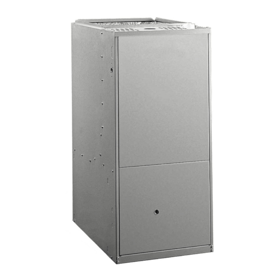
HIGH EFFICIENCY
GAS-FIRED FURNACES
TUBULAR HEAT EXCHANGER SERIES
MODELS: P*UR / G9T-UP / FG9-UP (Upflow)
40 - 140 MBH INPUT
MODELS: P*DH / G9T-DH / FG9-DH (Downflow / Horizontal)
40 - 120 MBH INPUT
EFFICIENCY
RATING
CERTIFIED
035-17477-001 Rev. A (801)
Advertisement
Table of Contents

Related Manuals for York P*UR


Summary of Contents for York P*UR
-
Page 1: Table Of Contents
INSTALLATION HIGH EFFICIENCY GAS-FIRED FURNACES INSTRUCTION TUBULAR HEAT EXCHANGER SERIES MODELS: P*UR / G9T-UP / FG9-UP (Upflow) 40 - 140 MBH INPUT MODELS: P*DH / G9T-DH / FG9-DH (Downflow / Horizontal) 40 - 120 MBH INPUT CONTENTS GENERAL INFORMATION ..... . . 2 SPECIFIC UNIT INFORMATION . -
Page 2: General Information
035-17477-001 Rev. A (801) GENERAL INFORMATION DESCRIPTION This Category IV, dual certified direct vent and 1-pipe vent IMPROPER INSTALLATION MAY CREATE A furnace is designed for residential or commercial applica- CONDITION WHERE THE OPERATION OF THE tion. It may be installed without modification to the conden- PRODUCT COULD CAUSE PERSONAL INJURY sate system in a basement, garage, equipment room, alcove, OR PROPERTY DAMAGE. -
Page 3: Specific Unit Information
035-17477-001 Rev. A (801) VENT SAFETY CHECK PROCEDURE SPECIFIC UNIT INFORMATION LIMITATIONS & LOCATION This furnace should be installed in accordance with all national and local building/safety codes and requirements, or This furnace may not be common vented with any in the absence of local codes, with the National Fuel Gas other appliance, since it requires separate, prop- Code ANSI Z223.1 or CAN/CGA B149.1 or.2 Installation... - Page 4 035-17477-001 Rev. A (801) The furnace shall be located using these guidelines: Where a minimum amount of air intake/vent piping and elbows will be required. Furnaces shall not be installed directly on carpet- As centralized with the air distribution as possible. ing, tile or other combustible material other than Where adequate combustion air will be available (partic- wood flooring.
- Page 5 1. Vent pipe must be increased to 3” on this unit. VENT CONNECTION CONNECTION TOP IMAGE BOTTOM IMAGE (vent size) DIMENSIONS - UPFLOW MODELS: P*UR/G9T-UP/FG9-UP FIGURE 1 : Table 1: RATINGS & PHYSICAL / ELECTRICAL DATA - UPFLOW MODELS MODELS P*UR / G9T-UP / MAX. MIN WIRE...
- Page 6 035-17477-001 Rev. A (801) VENT CONNECTION T'STAT WIRING 7/8 K.O. CONDENSATE CONDENSATE DRAIN ACCESS 1-3/4 DRAIN ACCESS 3-1/4 x 3 3-1/4 x 3 5-1/4 16-3/4 18-1/2 AIR INTAKE 3-3/4 AIR INTAKE 3-5/8 x 3-5/8 1-1/4 3-5/8 x 3-5/8 CONN. SIZE/ CONN.
-
Page 7: Ductwork
FRONT REAR FLUE CLOSET ALCOVE ATTIC CON- SIDE SIDE BOTTOM TACT UPFLOW MODELS (P*UR / G9T-UP / FG9-UP) UPFLOW COMBUSTIBLE DOWNFLOW / HORIZONTAL MODELS (P*DH / G9T-DH / FG9-DH ) DOWNFLOW 1" † † ‡ HORIZONTAL 1” Special floor base or air conditioning coil required for use on combustible floor. - Page 8 All applications require the use of a filter. A high velocity filter beyond opening edge as much as possible to prevent air and retainer are provided for field installation on P*UR & from bypassing the filter. DO NOT remove stiffening rods G9T-UP models.
- Page 9 035-17477-001 Rev. A (801) The return duct may be attached to the furnace by S-cleat, Horizontal Installations bend tabs or other approved methods. Be sure to seal the For installation of an air conditioning coil in a horizontal appli- duct to the furnace to prevent air leakage. cation, the perforations in the wrapper flanges must be bent Where the return duct system is not complete, the return con- away from the heat exchanger to create duct flanges so the...
- Page 10 035-17477-001 Rev. A (801) DOWNFLOW/HORIZONTAL MODELS FILTER RACK (FACTORY SUPPLIED) HORIZONTAL APPLICATION RACK AND FILTERS SECURED INSIDE BLOWER SECTION FOR SHIPMENT CASING SIZE DIMENSION FH 16-1/4 12-3/4 22-1/4 26-1/4 8-1/4 NOTE: FILTER ACCESS THRU DUCT- Downflow furnaces may be installed horizontally with the sup- BRANCH WORK MUST BE PROVIDED FOR ply airflow toward the left or right by laying the unit on the left...
-
Page 11: Gas Piping
035-17477-001 Rev. A (801) This appliance is design certified for line contact for furnaces When suspending the furnace from rafters or floor joists using installed horizontally. The intersection of the furnace top and rod, pipe or straps, refer to the Physical and Rating Data sides form a line. -
Page 12: Electrical Power Connection
035-17477-001 Rev. A (801) INLET GAS PRESSURE RANGE Natural Gas Propane (LP) Never apply a pipe wrench to the body of the com- Minimum 4.5 In. W.C. 11 In. W.C. bination automatic gas valve. A wrench must be Maximum 13.9 In. W.C. 13.9 In. -
Page 13: Electrical Control Connections
035-17477-001 Rev. A (801) ELECTRICAL CONTROL CONNECTIONS (HOT) Install the field-supplied thermostat. The thermostat instruc- BLK/BLK WHT/WHT tions for wiring are packed with the thermostat. With the ther- GRN/GRN mostat set in the OFF position and the main electrical source disconnected, complete the low-voltage wiring from the ther- mostat to the terminal board on the ignition module. -
Page 14: Combustion Air And Vent System
035-17477-001 Rev. A (801) ACCESSORY CONNECTIONS Be sure to follow the appropriate venting section details, related information and limitations for your type of installation. The furnace control will allow power switching control of vari- ous accessories. Refer to Figure 15, for connection details. Furnace Intake / Vent Connection Size (All Models) ELECTRONIC AIR CLEANER CONNECTION 40 - 100 MBH... - Page 15 Table 4: INTAKE/VENT PIPING - 2 PIPE SYSTEM pool chemicals might be stored. Be sure the terminal assem- Max. Elbows vs. One Way Vent bly follows the outdoor clearances listed in Table 3 for U.S. Models P*UR/ Pipe installations. In Canada, refer to CAN/CGA-B149.1 or.2 Length (Ft.)
- Page 16 035-17477-001 Rev. A (801) Termination should be located where it will not be dam- Table 5: INTAKE/VENT PIPING 2-PIPE SYSTEM aged or exposed to flying stones, balls, etc. Max. Elbows vs. One Way Models P*DH/ Termination should be positioned where vent vapors are Pipe Size Vent Length (Ft.) FG9-DH/G9T-DH...
- Page 17 035-17477-001 Rev. A (801) OVERHANG VENT 12” MINIMUM VENT 12 SEPARATION BETWEEN 90° BOTTOM OF COMBUSTION AIR AND BOTTOM OF VENT MAINTAIN 12” CLEARANCE ABOVE HIGHEST ANTICIPATED SNOW LEVEL OR GRADE WHICHEVER IS GREATER COMBUSTION AIR COMBUSTION AIR 2” FIGURE 19 : Horizontal Termination Raised FIGURE 22 : Double Sidewall Termination Configuration for Additional Clearance OVERHANG...
- Page 18 035-17477-001 Rev. A (801) VENT PIPE CEMENTS COMBUSTION AIR INTO SOCKET JUST UNDER TOP PANEL Solvent cements are flammable and must be used in well-ventilated areas only. Keep them away from heat, sparks and open flames (including pilots). Do not breathe vapors and avoid contact with skin and eyes.
- Page 19 035-17477-001 Rev. A (801) Air Source from Inside the Building Louvers, Grilles and Screens Two permanent openings, one within 12 inches of the top of In calculating free area, consideration must be given the confined space and one within 12 inches of the bottom, to the blocking effects of louvers, grilles and shall each have a free area of not less than one square inch screens.
- Page 20 035-17477-001 Rev. A (801) The following types of installations may require OUT- All vent pipe and fittings must conform to American DOOR AIR for combustion, due to chemical exposure. National Standards Institute (ANSI) standards and Amer- ican Society for Testing and Materials (ASTM) standards Commercial buildings D1785 (Schedule 40 PVC), D2665 (PVC-DWV), F891 Buildings with indoor pools...
- Page 21 035-17477-001 Rev. A (801) VENT TERMINAL LOCATION CLEARANCES The vent must be installed with the following minimum clear- ances (refer to Figure 26), and complying with local codes or utility requirements or other authority having jurisdiction. SOFFIT 12" VENTS 4” 4”...
- Page 22 035-17477-001 Rev. A (801) PIPING ASSEMBLY METHOD THREE: TWO PIPE SYSTEM USING COM- BUSTION AIR FROM A VENTILATED ATTIC SPACE The final assembly procedure for the vent piping is as follows: This type installation requires two properly sized pipes. One Cut piping to the proper length, beginning at the furnace.
- Page 23 035-17477-001 Rev. A (801) COMBUSTION AIR REQUIREMENTS The ventilated attic space from which the combustion air is taken must comply with the requirements shown on page 18 in this instruction or in Section 5.3, Air for Combustion and Ventilation of the National Fuel Gas Code, ANSI Z223.1 (lat- est edition).
-
Page 24: Condensate Piping
035-17477-001 Rev. A (801) CONDENSATE PIPING Refer to Figure 35 for hose locations and Table 8 for hose cut lengths. All hoses are identified as shown in Figure 35. The condensate drain connection is packed in the furnace for For horizontal left airflow (inducer and vent low) or horizontal field installation. -
Page 25: Safety Controls
035-17477-001 Rev. A (801) HOSE IDENTIFIER NUMBERS: 1. CONDENSATE PAN TO TRAP “A” DIMENSIONS. RIGHT AIRFLOW (INDUCER HIGH) 2. INDUCER BOTTOM TO TRAP “B” DIMENSIONS. 3. INDUCER OUTLET TO TRAP “C” DIMENSIONS. HOSE IDENTIFIER NUMBERS: LEFT AIRFLOW 1. INDUCER OUTLET TO TRAP USE AS PROVIDED. (INDUCER HIGH) 5. -
Page 26: Start-Up And Adjustments
035-17477-001 Rev. A (801) Perform the following procedures only after the condensate trap has been properly piped to a drain connection using the procedure in this instruction. The condensate trap must be filled with water before put- ting the furnace into operation. The recommended pro- UPFLOW cedure is as follows: Disconnect the condensate drain hose from the... - Page 27 035-17477-001 Rev. A (801) Read across to the column headed 1 Cubic Foot where you will see that 138 cubic feet of gas per hour are consumed by the furnace at that rate. Multiply 138 by 850 (the BTU rating of the gas obtained from the local gas company).
- Page 28 035-17477-001 Rev. A (801) Refer to Figure 37 on page 27, for location of pressure regulator adjustment cap and screw on main gas valve. Turn gas and electrical supplies ON. Start furnace and observe manifold pressure on manometer. Be sure to relight any gas appliances that were turned off at the start of this input check.
- Page 29 GAS PRESSURE WATER COLUMN SHOWN GAS PRESSURE SHOWN U-TUBE MANOMETER Upflow Models (P*UR/ FG9-UP / G9T-UP) - Reading Gas Pressure FIGURE 38 : WITH BURNER BOX COVER IN PLACE WITH BURNER BOX COVER REMOVED BURNER BOX WITH BURNER BOX COVER REMOVED...
-
Page 30: Furnace Accessories
Combustible Floor Base - Cabinet “A” 1CB0317 Combustible Floor Base - Cabinet “B” 1CB0321 Combustible Floor Base - Cabinet “C” 1CB0324 Combustible Floor Base - Cabinet “D” * Substitute 2 for York brands and 6 for non York brands. Unitary Products Group... - Page 31 035-17477-001 Rev. A (801) BLOWER PERFORMANCE CFM- UPFLOW (WITHOUT FILTER) MODELS EXTERNAL STATIC PRESSURE, INCHES WC Input/Output/Airflow/ SPEED TAP cabinet HIGH 1330 1260 1210 1150 1090 1025 MED-HIGH 40 / 37 / 1000 / "A" MED-LOW HIGH 1360 1330 1290 1250 1190 1130...
- Page 32 035-17477-001 Rev. A (801) AIRFLOW DATA - DOWNFLOW/HORIZONTAL MODELS: P*DH/G9T-DH/FG9-DH MODELS EXTERNAL STATIC PRESSURE, INCHES WC Input/Output/Airflow/ SPEED TAP cabinet HIGH 1400 1350 1300 1250 1200 1135 1060 MED-HIGH 40 / 37 / 1000 / "A” MED-LOW HIGH 1605 1590 1570 1545 1510...
-
Page 33: Operation And Maintenance
035-17477-001 Rev. A (801) APPLYING FILTER PRESSURE DROP TO DETERMINE OPERATION AND MAINTENANCE SYSTEM AIRFLOW SEQUENCE OF OPERATION To determine the approximate airflow of the unit with a filter in The following describes the sequence of operation of the fur- place, follow the steps below: nace. - Page 34 035-17477-001 Rev. A (801) The blower motor continues to operate for the amount of time All filters used with the furnace are the high-velocity, clean- set by the fan-off delay "Jumper" located on the ignition con- able type. Clean these filters by washing in warm water. trol board (Figure 16).
- Page 35 035-17477-001 Rev. A (801) HORIZONTAL APPLICATIONS LUBRICATION In most horizontal applications the filter is located in the Blower motors in these furnaces are permanently lubricated return air duct near the furnace or in a filter grille. and do not require periodic oiling. When replacing filters, DO NOT use a type with excessively high pressure drop.
-
Page 36: Troubleshooting
035-17477-001 Rev. A (801) BURNER REMOVAL/CLEANING CLEANING THE SECONDARY HEAT EXCHANGER The main burners should be checked periodically for dirt Follow steps 1 thru 10 under Cleaning the Primary Heat accumulation. Exchanger. If cleaning is required, follow this procedure: Remove the vent piping from the venter housing. Discon- nect the drain lines from the venter and from the conden- Turn off the electrical power to the unit. - Page 37 035-17477-001 Rev. A (801) All flash code sequences are broken by a 2 second “off” 8 FLASH: This fault is indicated if the flame is lost 5 times (4 period. recycles) during the heating cycle. This could be caused by low gas pressure or faulty gas valve.
- Page 38 035-17477-001 Rev. A (801) WIRING DIAGRAM - UPFLOW MODELS: P*UR / FG9-UP / G9T-UP NOTE: THE FURNACE’S CONTROL SYSTEM REQUIRES CORRECT POLARITY OF THE POWER SUPPLY. Unitary Products Group...
- Page 39 035-17477-001 Rev. A (801) WIRING DIAGRAM - DOWNFLOW/HORIZONTAL MODELS: P*DH / FG9-DH / G9T-DH NOTE: THE FURNACE’S CONTROL SYSTEM REQUIRES CORRECT POLARITY OF THE POWER SUPPLY. Unitary Products Group...
- Page 40 Subject to change without notice. Printed in U.S.A. 035-17477-001 Rev. A (801) Copyright © by York International Corp. 2001. All rights reserved. Supersedes: 035-17477-000 Rev. A (800) Unitary 5005 Norman Product York Group Drive 73069...