Yamaha RX-V750 Owner's Manual
Hide thumbs
Also See for RX-V750:
- Service manual (128 pages) ,
- Owner's manual (92 pages) ,
- Supplementary manual (40 pages)
Table of Contents
Advertisement
Quick Links
Advertisement
Table of Contents

Related Manuals for Yamaha RX-V750


Summary of Contents for Yamaha RX-V750
- Page 1 RX-V750 AV Receiver OWNER'S MANUAL...
-
Page 2: Important Safety Instructions
IMPORTANT SAFETY INSTRUCTIONS IMPORTANT SAFETY INSTRUCTIONS 10 Ventilation – Slots and openings in the cabinet are provided for ventilation and to ensure reliable operation of the CAUTION product and to protect it from overheating, and these RISK OF ELECTRIC SHOCK openings must not be blocked or covered. - Page 3 Modifications not expressly approved by following measures: Yamaha may void your authority, granted by the FCC, to use the product. Relocate either this product or the device that is being 2 IMPORTANT: When connecting this product to affected by the interference.
- Page 4 Since hearing damage from loud sounds is often Electronics Group want you to get the most out of your undetectable until it is too late, YAMAHA and the equipment by playing it at a safe level. One that lets the sound Electronic Industries Association’s Consumer...
-
Page 5: Table Of Contents
CONTENTS INTRODUCTION SOUND FIELD PROGRAMS FEATURES............. 2 SOUND FIELD PROGRAM GETTING STARTED..........3 DESCRIPTIONS..........46 Supplied accessories ..........3 For movie/video sources.......... 46 Installing batteries in the remote control ....3 For music sources ............ 48 CONTROLS AND FUNCTIONS ......4 Front panel .............. -
Page 6: Features
8 additional input jacks for discrete multi-channel input On-screen display function helpful in controlling this Sound field features unit Proprietary YAMAHA technology for the creation of S Video signal input/output capability sound fields Component video input/output capability Dolby Digital/Dolby Digital EX decoder Video signal conversion (Composite video ↔... -
Page 7: Getting Started
GETTING STARTED GETTING STARTED Supplied accessories Please check that you received all of the following parts. Remote control Batteries (4) AM loop antenna 75-ohm/300-ohm antenna adapter (AAA, R03, UM-4) (U.K. model only) TRANSMIT RE-NAME CLEAR LEARN SYSTEM POWER STANDBY SLEEP INPUT MODE PHONO MULTI CH IN... -
Page 8: Controls And Functions
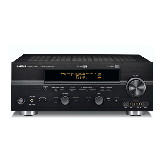
CONTROLS AND FUNCTIONS CONTROLS AND FUNCTIONS Front panel (U.S.A. model) VOLUME OPTIMIZER l PRESET/TUNING h PRESET/TUNING FM/AM A/B/C/D/E MEMORY TUNING MODE EDIT NEXT LEVEL MAN'L/AUTO FM AUTO/MAN'L MONO PROGRAM INPUT PHONES SPEAKERS STRAIGHT TONE CONTROL INPUT MODE MULTI CH PURE DIRECT INPUT STANDBY VIDEO AUX... - Page 9 CONTROLS AND FUNCTIONS U.K. and Europe models only PHONES (SILENT CINEMA) Outputs audio signals for private listening with L RDS MODE/FREQ headphones. When you connect headphones, no signals Press this button when the unit is receiving an RDS station are output to the OUTPUT jacks or to the speakers. to cycle the display mode between the PS mode, PTY All Dolby Digital and DTS audio signals are mixed down mode, RT mode, CT mode (if the station offers those RDS...
-
Page 10: Remote Control
CONTROLS AND FUNCTIONS Remote control 3 STANDBY This section describes the function of each control on the remote control. See “REMOTE CONTROL FEATURES” Sets this unit in the standby mode. on page 63 to operate other components with this remote 4 SYSTEM POWER control. - Page 11 CONTROLS AND FUNCTIONS G MULTI CH IN U.K. and Europe models only Selects the MULTI CH INPUT mode when using an R RDS tuning buttons external decoder (etc.). FREQ/RDS H SELECT k/n Press this button when the unit is receiving an RDS station Selects another component that you can control to cycle the display mode between the PS mode, PTY independently of the input component selected with the...
-
Page 12: Using The Remote Control
CONTROLS AND FUNCTIONS Using the remote control The remote control transmits a directional infrared beam. Be sure to aim the remote control directly at the remote control sensor on the main unit during operation. VOLUME OPTIMIZER PRESET/TUNING FM/AM A/B/C/D/E l PRESET/TUNING h MEMORY TUNING MODE EDIT... -
Page 13: Front Panel Display
CONTROLS AND FUNCTIONS Front panel display DVR/VCR2 VCR-1 V-AUX DTV/CBL MD/CD-R TUNER PHONO SILENT CINEMA NIGHT ZONE2 PTY HOLD AUTO TUNED STEREO MEMORY MUTE VOLUME MATRIX DISCRETE VIRTUAL OPTIMIZER HiFi DSP DIGITAL SLEEP RT CT 96/24 L C R PL x SL SB SR (U.S.A., Canada and (U.K. - Page 14 CONTROLS AND FUNCTIONS 96/24 indicator Lights up when a DTS 96/24 signal is input to this unit. L LFE indicator Lights up when the input signal contains the LFE signal. M Input channel indicators Indicates the channel components of current digital input signal.
-
Page 15: Rear Panel
CONTROLS AND FUNCTIONS Rear panel COMPONENT VIDEO TUNER 75Ω UNBAL. AUDIO AUDIO /CBL PHONO VIDEO VIDEO S VIDEO REMOTE DIGITAL MONITOR INPUT ZONE 2 PRE OUT AC OUTLETS SWITCHED CENTER COAXIAL (PLAY) /CBL CONTROL /CD-R OPTICAL DTV/CBL (REC) +12V VCR 1 SURROUND PRESENCE/ZONE 2 15mA MAX. -
Page 16: Speaker Setup
Ideally, they should be positioned at the same width as the front speakers. Subwoofer 60˚ The use of a subwoofer, such as the YAMAHA Active 80˚ Servo Processing Subwoofer System, is effective not only for reinforcing bass frequencies from any or all channels,... -
Page 17: Speaker Connections
SPEAKER SETUP Speaker connections Tighten the knob to secure the wire. Be sure to connect the left channel (L), right channel (R), “+” (red) and “–” (black) properly. If the connections are faulty, no sound will be heard from the speakers, and if the polarity of the speaker connections is incorrect, the sound will be unnatural and lack bass. - Page 18 SPEAKER SETUP Presence speakers Surround speakers Subwoofer system Right Left Right Left PRE OUT CENTER SURROUND PRESENCE/ZONE 2 FRONT SURROUND WOOFER BACK SPEAKERS SURROUND FRONT CENTER SURROUND BACK (U.S.A. model) Front speakers Center speaker Right Left Right Left Surround back Front speakers (A) speakers You can connect both surround back and presence speakers to this unit, but they do not output sound simultaneously.
- Page 19 SURROUND terminals Connect surround speakers to these terminals. SUBWOOFER jack Connect a subwoofer with built-in amplifier, such as the YAMAHA Active Servo Processing Subwoofer System, to this jack. Speaker layout SURROUND BACK terminals Connect surround back speakers to these terminals. If you only connect one surround back speaker, connect it to the left (L) terminals.
-
Page 20: Connections
CONNECTIONS CONNECTIONS Dust protection cap Before connecting components Pull out the cap from the optical jack before you connect the fiber optic cable. Do not discard the cap. When you are not using the optical jack, be sure to put the cap back in CAUTION place. -
Page 21: Connecting Video Components
CONNECTIONS Connecting video components Connections for DVD playback Optical out Video out Coaxial out DVD player Audio out COMPONENT VIDEO AUDIO /CBL VIDEO VIDEO S VIDEO DIGITAL MONITOR Video in Video INPUT monitor COAXIAL /CBL VCR 1 DVR/ VCR 2 VIDEO S VIDEO MONITOR OUT... - Page 22 CONNECTIONS Connecting to the MULTI CH INPUT jacks This unit is equipped with 8 additional input jacks (left and right FRONT, CENTER, left and right SURROUND, left and right SURROUND BACK and SUBWOOFER) for discrete multi-channel input from a multi-format player, external decoder, sound processor or pre-amplifier.
- Page 23 CONNECTIONS Connections for other video components Optical out Cable TV or Video out satellite tuner Audio out COMPONENT VIDEO AUDIO /CBL VIDEO VIDEO S VIDEO DIGITAL MONITOR INPUT /CBL OPTICAL DTV/CBL VCR 1 DVR/ VCR 2 VIDEO S VIDEO MONITOR OUT (U.S.A.
-
Page 24: Connecting Audio Components
CONNECTIONS Connecting audio components Connections for audio components Turntable Audio out AUDIO AUDIO PHONO DIGITAL Audio out INPUT CD player Audio out COAXIAL (PLAY) MD recorder or /CD-R OPTICAL tape deck (REC) Coaxial out Audio in Optical out MD/CD-R Optical in MD/CD-R OPTICAL DIGITAL... -
Page 25: Connecting To An External Amplifier
Surround back or presence channel line output jacks. 5 SUBWOOFER PRE OUT jack Connect a subwoofer with built-in amplifier, such as the YAMAHA Active Servo Processing Subwoofer System, to this jack. Notes • Each PRE OUT jack outputs the same channel signal as the corresponding speaker terminals. -
Page 26: Connecting The Antennas
If you experience poor reception quality, an (included) AM loop antenna (included) outdoor antenna may improve the quality. Consult the nearest authorized YAMAHA dealer or service center about outdoor antennas. 75-ohm/300-ohm antenna adapter (U.K. model only) TUNER 75Ω... -
Page 27: Connecting The Power Supply Cord
CONNECTIONS Connecting the power supply cord Memory back-up Connecting the AC power cord The memory back-up circuit prevents the stored data from Plug the power cord into an AC wall outlet. being lost even if this unit is in the standby mode. However if the power cord is disconnected from the AC AC OUTLET(S) (SWITCHED) wall outlet, or the power supply is cut for more than one... -
Page 28: Impedance Selector Switch
CONNECTIONS IMPEDANCE SELECTOR switch CAUTION Do not change the setting of the IMPEDANCE SELECTOR switch when the unit power is switched on, as doing so may damage the unit. If this unit fails to turn on when STANDBY/ON is pressed on either the front panel or remote control, the IMPEDANCE SELECTOR switch may not be fully slid to either position. -
Page 29: Turning On The Power
CONNECTIONS Turning on the power When all connections are complete, turn on the power of this unit. VOLUME OPTIMIZER l PRESET/TUNING h PRESET/TUNING FM/AM A/B/C/D/E MEMORY TUNING MODE EDIT NEXT LEVEL MAN'L/AUTO FM AUTO/MAN'L MONO PROGRAM INPUT PHONES SPEAKERS STRAIGHT TONE CONTROL INPUT MODE MULTI CH... -
Page 30: Auto Setup
AUTO SETUP AUTO SETUP Introduction Optimizer microphone setup This receiver employs YAMAHA Parametric Room Acoustic Optimizer (YPAO) technology which lets you Connect the supplied optimizer microphone avoid troublesome listening-based speaker setup and to the OPTIMIZER MIC jack on the front achieves highly accurate sound adjustments. -
Page 31: Starting The Setup
AUTO SETUP Starting the setup Press u to select the desired parameter, then press j to select the desired setting. For best results, make sure the room is as quiet as possible during the auto setup procedure. If there is too much 1 AUTO SETUP ambient noise, the results may not be satisfactory. - Page 32 AUTO SETUP If you set SETUP to AUTO in step 6 If you set SETUP to RELOAD in step 6 The RESULT display appears for a few seconds after each The RESULT:EXIT display appears. check, then settings of the next item will start. The RESULT:EXIT display appears after all items are set.
- Page 33 AUTO SETUP Troubleshooting for auto setup procedure Before auto setup Error message Cause Remedy Connect MIC! Optimizer microphone is not connected. • Connect the supplied optimizer microphone to the OPTIMIZER MIC jack on the front panel. Unplug HP! Headphones are connected. •...
-
Page 34: Playback
PLAYBACK PLAYBACK Basic operations Select the input source. Use INPUT (or press one of the input selector buttons on the remote control) to select the input you desire. PHONO MULTI CH IN INPUT V-AUX TUNER MD/CD-R DTV/CBL VCR 1 DVR/VCR2 VOLUME OPTIMIZER PRESET/TUNING... - Page 35 PLAYBACK To adjust the tone Select a sound field program if desired. You can adjust the tonal quality TONE CONTROL of your front left/right, center, Use PROGRAM (or press AMP to select the AMP presence and subwoofer speakers mode, then press one of the sound field program or headphones (when connected).
-
Page 36: Selecting Sound Field Programs
PLAYBACK Selecting the MULTI CH INPUT Selecting sound field programs Press MULTI CH INPUT so that “MULTI CH INPUT” appears in the front panel display and video monitor. Front panel operation MULTI CH INPUT MULTI CH IN VOLUME Front panel Remote control OPTIMIZER PRESET/TUNING... - Page 37 PLAYBACK Remote control operation Enjoying multi-channel software If you connected a surround back speaker, use this feature to enjoy 6.1/7.1-channel playback for multi-channel LEVEL SET MENU MUTE TITLE MENU TV VOL TV INPUT A/B/C/D/E TRANSMIT RE-NAME CLEAR LEARN sources using the Dolby Pro Logic IIx, Dolby Digital SYSTEM TV MUTE POWER...
- Page 38 PLAYBACK Enjoying 2-channel software Notes Signals input from 2-channel sources can also be played • Some 6.1-channel compatible discs do not have a signal (flag) back on multiple channels. which this unit can automatically detect. When playing these Press q/DTS on the remote control to select the kinds of discs with 6.1-channel, manually select a decoder (PLIIx Movie, PLIIx Music, EX/ES or EX).
-
Page 39: Night Listening Mode
PLAYBACK Listening to high fidelity stereo sound Night listening mode (PURE DIRECT) This mode reproduces dialogue clearly while reducing the volume of loud sound effects for easier listening at low PURE DIRECT allows you to bypass this unit’s decoders volumes or at night. and DSP processors to enjoy pure high fidelity sound from 2-channel PCM and analog sources. -
Page 40: Selecting Input Modes
PLAYBACK Downmixing to 2 channels Selecting input modes You can enjoy 2-channel stereo playback even from multi- channel sources. This unit comes with a variety of input jacks. Do the Rotate PROGRAM (or press STEREO on the following to select the type of input signals you want to remote control) to select 2ch Stereo. - Page 41 PLAYBACK Notes Press u / d to display the following • When you play DTS encoded sources with the input mode set to information about the input signal. AUTO: – This unit automatically switches to the DTS decoding mode. The unit remains in DTS mode (and the “t” indicator may TV VOL flash) for up to 30 second after playback of the DTS source is complete.
-
Page 42: Tuning
TUNING TUNING Automatic and manual tuning Press TUNING MODE (AUTO/MAN’L MONO) so that the “AUTO” indicator lights up on the There are 2 tuning methods; automatic and manual. front panel display. Automatic tuning is effective when station signals are strong and there is no interference. TUNING MODE AUTO Automatic tuning... -
Page 43: Presetting Stations
TUNING Manual tuning Presetting stations If the signal from the station you want to select is weak, tune into it manually. Automatically presetting FM stations You can use the automatic preset tuning feature to store Select TUNER and the reception band FM stations. - Page 44 TUNING Manually presetting stations Press and hold MEMORY (MAN’L/AUTO FM) You can also store up to 40 stations (8 stations x 5 groups) manually. for more than 3 seconds. The preset number, the “MEMORY” and “AUTO” indicators flash. After about 5 seconds, automatic presetting starts from the frequency currently VOLUME displayed and proceeds toward the higher frequencies...
-
Page 45: Selecting Preset Stations
TUNING Selecting preset stations Press PRESET/TUNING l / h to select a preset station number (1 to 8) while the You can tune any desired station simply by selecting the “MEMORY” indicator is flashing. preset station number under which it was stored. Press h to select a higher preset station number. -
Page 46: Exchanging Preset Stations
TUNING Exchanging preset stations Press PRESET/TUNING (EDIT) again. The stations stored at the two preset assignments are You can exchange the assignment of two preset stations exchanged. with each other. The example below describes the procedure for exchanging preset station “E1” with “A5”. PRESET/TUNING EDIT VOLUME... -
Page 47: Receiving Rds Stations
TUNING Receiving RDS stations Changing the RDS mode RDS (Radio Data System) is a data transmission system The four modes are available in this unit for displaying used by FM stations in many countries. The RDS function RDS data. The PS, PTY, RT and/or CT mode indicators is carried out among the network stations. -
Page 48: Pty Seek Function
TUNING PTY SEEK function EON function If you select the desired program type, this unit This function uses the EON data service on the RDS automatically searches all preset RDS stations that are station network. If you select the desired program type broadcasting a program of the required type. -
Page 49: Recording
RECORDING RECORDING Recording adjustments and other operations are Notes performed from the recording components. Refer to the • Do a test recording before you start an actual recording. operation instructions for those components. • When this unit is set in the standby mode, you cannot record between other components connected to this unit. -
Page 50: Sound Field Program Descriptions
The YAMAHA CINEMA DSP modes are compatible with all Dolby Digital, DTS, and Dolby Surround sources. Set INPUT MODE to AUTO (see page 36) to enable this unit to automatically switch to the appropriate digital decoder according to the input signal. - Page 51 SOUND FIELD PROGRAM DESCRIPTIONS Program Features Sources Standard 5.1-channel processing for DTS and 96kHz/24-bit DTS sources. SUR. STANDARD CINEMA DSP enhanced processing for DTS sources. SUR. ENHANCED DTS+PLIIx Movie Standard 6.1/7.1 channel processing (Dolby Pro Logic IIx) for DTS sources. SUR.
-
Page 52: For Music Sources
SOUND FIELD PROGRAM DESCRIPTIONS For music sources You can select from the following sound fields when playing music sources, like CD, FM/AM broadcasting, tapes, etc. Program Features Sources CONCERT HALL HiFi DSP processing. A classic shoe-box type concert hall with approximately 1700 seats. Pillars and ornate carvings create extremely complex reflections which produce a very full, rich sound. -
Page 53: Advanced Operation
ADVANCED OPERATIONS ADVANCED OPERATIONS Selecting the OSD mode Using the sleep timer You can display this unit’s operating information on a Use this feature to automatically set this unit in the video monitor. If you display the SET MENU and sound standby mode after a certain amount of time. -
Page 54: Manually Adjusting Speaker Levels
ADVANCED OPERATIONS Canceling the sleep timer Manually adjusting speaker levels Press SLEEP repeatedly until “SLEEP OFF” appears on the front panel display. You can adjust the output level of each speaker while After a few seconds, “SLEEP OFF” disappears, and the listening to a music source. -
Page 55: Using The Test Tone
ADVANCED OPERATIONS Using the test tone You can use the test tone feature to manually balance your speaker levels. Please note that this operation will override the level adjustments made in “AUTO SETUP” (page 26), “SP LEVEL” (page 57) and “Manually adjusting speaker levels”... -
Page 56: Setup Menu
SETUP MENU SETUP MENU You can use the following parameters in the setup menu to adjust a variety of system settings and customize the way this unit operates. Change the initial settings (indicated in bold under each parameter) to reflect the needs of your listening environment. - Page 57 SETUP MENU 3 OPTION MENU Use to adjust the optional system settings. Item Features Page A)DISPLAY SET Adjusts the brightness of the display and converts video signals. B)MEMORY GUARD Locks sound field program parameters and other setup menu settings. C)PARAM. INI Initializes the parameters of a group of sound field programs.
-
Page 58: Using The Setup Menu
SETUP MENU Using the setup menu Press SELECT to enter MANUAL SETUP. 1 SOUND MENU appears on the front panel display. Use the remote control to access and adjust each parameter. MANUAL SETUP TV VOL . 1 SOUND MENU POWER POWER 2 INPUT MENU 3 OPTION MENU... -
Page 59: Sound Menu
SETUP MENU 1 SOUND MENU Use to manually adjust any speaker setting or compensate for video signal processing delays when using LCD monitors or projectors. Most of the 1 SOUND MENU parameters are set automatically when you run auto setup (see page 26). - Page 60 SETUP MENU FRONT Front speakers Surround back left/right speakers SURR.B Choices: LARGE, SMALL Choices: LRGx2, LRGx1, SMLx2, SMLx1, NONE FRONT SURR.B [SMALL LARGE SWLx1 [SMLx2 • Select LARGE if you have large front speakers. The • Select LRGx2 if you have 2 large surround back unit directs the entire range of the front left and right speakers.
- Page 61 SETUP MENU LFE/Bass out BASS OUT Speaker level B)SP LEVEL LFE signals carry low-frequency effects when this unit Use these settings to manually balance the speaker levels decodes a Dolby Digital or DTS signal. The Low- between the front left or surround left speakers and each frequency signals can be directed to both front left and speaker selected in A) SPEAKER SET (page 55).
- Page 62 SETUP MENU Speaker distance C)SP DISTANCE Low-frequency effect level E)LFE LEVEL Use this feature to manually input the distance of each Use to adjust the output level of the LFE (low-frequency speaker and adjust the delay applied to respective channel. effect) channel according to the capacity of your Ideally, each speaker should be the same distance from the subwoofer or headphones.
-
Page 63: Input Menu
SETUP MENU Audio set G)AUDIO SET 2 INPUT MENU Use to customize this units overall audio settings. Use to reassign digital input/outputs, select the input mode G)AUDIO SET or rename your inputs. . AUDIO MUTE;;MUTE AUDIO DELAY;;0ms DIALG.LIFT;;;OFF 2 INPUT MENU : Exit -/+ : Select . - Page 64 SETUP MENU For COAXIAL INPUT jacks 5 and 6 Input rename C)INPUT RENAME Choices: CD, V-AUX, DTV/CBL, VCR, DVD, MD/CD-R Use this feature to change the name of the inputs on the OSD and front panel display. COAXIAL IN C)INPUT RENAME .
-
Page 65: Option Menu
SETUP MENU Component OSD CMPNT OSD 3 OPTION MENU Use this feature to turn on/off OSD output to the COMPONENT VIDEO MONITOR OUT jacks when Use to adjust the optional system settings. using the set menu, test tone or parameter functions. Choices: ON, OFF 3 OPTION MENU •... - Page 66 SETUP MENU Zone 2 set E)ZONE2 SET Notes (U.S.A., Canada and Australia models only) • You cannot automatically revert to the previous parameter sound settings once you initialize a field program group. E)ZONE2 SET sound • You cannot separately initialize individual field OUTPUT VOL;;VAR.
-
Page 67: Remote Control Features
REMOTE CONTROL FEATURES REMOTE CONTROL FEATURES In addition to controlling this unit, the remote control can also operate other A/V components made by YAMAHA and other manufacturers. To control other components, you must set up remote control with the appropriate manufacturer codes. -
Page 68: Setting Manufacturer Codes
Note • The initial setting for “Amplifier library” is “YPC”. You may not be able to operate your Yamaha component even if a To operate this unit. Yamaha manufacturer code is initially set as listed above. In this ZONE (U.S.A., Canada and Australia models only) -
Page 69: Programming Codes From Other Remote Controls
AV components apart from the other remote control on a flat (including Yamaha AV components). If operation is not surface so that their infrared transmitters are possible with any of the manufacturer codes, program the new aimed at each other. - Page 70 REMOTE CONTROL FEATURES Notes Press LEARN using a ballpoint pen or similar object. • “NG” appears in the display window if programming was Do not press and hold LEARN. If you hold it down unsuccessful. In this case, start over from step 5. •...
-
Page 71: Changing Source Names In The Display Window
REMOTE CONTROL FEATURES Changing source names in the Press RE-NAME again to exit from the display window renaming mode. You can change the name that appears in the display RE-NAME window on the remote control if you want to use the different name than the factory preset. -
Page 72: Clearing Function Sets
REMOTE CONTROL FEATURES Clearing function sets Press CLEAR to exit from the clearing mode. Once you have cleared a learned function for a You can clear all changes made in each function set, such button, the button reverts to the factory setting. as learned functions, renamed source names and setup manufacturer codes. -
Page 73: Clearing Individual Functions
REMOTE CONTROL FEATURES Clearing individual functions Repeat step 3 to clear other learned functions. Clearing a learned function You can clear the function learned in a certain Press LEARN again to exit. programmed button in each area. Press an input selector button to select the source component containing the function you want to clear. -
Page 74: Controlling Other Components
REMOTE CONTROL FEATURES Controlling other components Once you set the appropriate manufacturer codes, you can use this remote to control your other components. Note that some buttons may not correctly operate the selected POWER POWER component. Use the input selector buttons to select the AUDIO component you want to operate. -
Page 75: (U.s.a., Canada And Australia Models Only)
• Since there are many possible ways to connect and use this unit in a multi-room installation, we recommend that you consult with the nearest authorized YAMAHA dealer or service center for the Zone 2 connections which will best meet your requirements. -
Page 76: Remote Controlling Zone 2
ZONE 2 (U.S.A., CANADA AND AUSTRALIA MODELS ONLY) Using this unit’s internal amplifier To use this unit’s internal amplifier, select ON in ZONE2 AMP. – PRESENCE/ ZONE 2 Second room This unit Remote controlling Zone 2 Press LEARN to complete the Zone setup. The remote control will be able to operate this unit The supplied remote control can be used to control Zone and Zone 2. - Page 77 ZONE 2 (U.S.A., CANADA AND AUSTRALIA MODELS ONLY) Turning this unit to either on or standby Press an input selector button to select the SYSTEM POWER and STANDBY work differently depending on the selected mode that appears on the input source you want to listen to in the display window.
-
Page 78: Editing Sound Field Parameters
The acoustics in your room could be changed to those of a concert hall, a dance floor, or virtually any size room at all. This ability to create sound fields at will is exactly what YAMAHA has done with the digital sound field processor. Program No. - Page 79 EDITING SOUND FIELD PARAMETERS Press u / d to select the parameters. TV VOL TV MUTE – SELECT PRESET PRESET TV VOL – Press j / i to change the parameter value. TV VOL When you set a parameter to a value other than the TV MUTE –...
-
Page 80: Sound Field Parameter Descriptions
SOUND FIELD PARAMETER DESCRIPTIONS SOUND FIELD PARAMETER DESCRIPTIONS You can adjust the values of certain digital sound field parameters so the sound fields are recreated accurately in your listening room. Not all of the following parameters are found in every program. DSP LEVEL Function: This parameter adjusts the level of all the DSP effect sounds within a narrow range. - Page 81 SOUND FIELD PARAMETER DESCRIPTIONS LIVENESS Function: This parameter adjusts the reflectivity of the virtual walls in the hall by changing the rate at which the early reflections decay. Description: The early reflections of a sound source decay much faster in a room with acoustically absorbent wall surfaces than in one which has highly reflective surfaces.
- Page 82 SOUND FIELD PARAMETER DESCRIPTIONS REV.TIME (Reverberation time) Function: This parameter adjusts the amount of time it takes for the dense, subsequent reverberation sound to decay by 60 dB (at 1 kHz). This changes the apparent size of the acoustic environment over an extremely wide range.
- Page 83 SOUND FIELD PARAMETER DESCRIPTIONS DIALG.LIFT (Dialog lift) Function: This parameter adjusts the height of the front and center channel sounds by assigning some of the front and center channel elements to the presence speakers. Description: The larger the parameter, the higher the position of the front and center channel sound. Choices: 0/1/2/3/4/5, initial setting is 3.
-
Page 84: Troubleshooting
Refer to the chart below when this unit does not function properly. If the problem you are experiencing is not listed below or if the instruction below does not help, set this unit to the standby mode, disconnect the power cord, and contact the nearest authorized YAMAHA dealer or service center. General... - Page 85 TROUBLESHOOTING Refer to Problem Cause Remedy page The sound suddenly The protection circuitry has been activated Check that the impedance selector setting is correct. goes off. because of a short circuit, etc. Check that the speaker wires are not touching each —...
- Page 86 TROUBLESHOOTING Refer to Problem Cause Remedy page Dolby Digital or DTS The connected component is not set to Make an appropriate setting following the operations — sources cannot be output Dolby Digital or DTS digital instructions for your component. played. (Dolby Digital signals.
- Page 87 TROUBLESHOOTING Refer to Problem Cause Remedy page There is noise This unit is too close to the digital or high- Move this unit further away from such equipment. — interference from frequency equipment. digital or high- frequency equipment, or this unit. The picture is The video source uses scrambled or Playing back video software that has an anti-copy...
- Page 88 TROUBLESHOOTING Remote control Refer to Problem Cause Remedy page The remote control Wrong distance or angle. The remote control will function within a maximum does not work nor range of 6 m (20 ft) and no more than 30 degrees off- function properly.
-
Page 89: Glossary
GLOSSARY GLOSSARY Dolby Surround Dolby Pro Logic II Dolby Surround uses a 4 channel analog recording system Dolby Pro Logic II is an improved technique used to to reproduce realistic and dynamic sound effects: 2 front decode vast numbers of existing Dolby Surround software. left and right channels (stereo), a center channel for dialog This new technology enables a discrete 5-channel (monaural), and a surround channel for special sound... - Page 90 SILENT CINEMA Sampling frequency and number of quantized bits YAMAHA has developed a natural, realistic sound effect DSP algorithm for headphones. When digitizing an analog audio signal, the number of Parameters for headphones have been set for each sound...
-
Page 91: Specifications
SPECIFICATIONS SPECIFICATIONS AUDIO SECTION VIDEO SECTION • Minimum RMS Output Power for Front, Center, Surround, • Video Signal Type Surround back [U.S.A., Canada and Korea models] ........NTSC 20 Hz to 20 kHz, 0.04% THD, 8 Ω ........110 W [Other models] ............ - Page 92 YAMAHA ELECTRONICS (UK) LTD. YAMAHA HOUSE, 200 RICKMANSWORTH ROAD WATFORD, HERTS WD18 7GQ, ENGLAND YAMAHA SCANDINAVIA A.B. J A WETTERGRENS GATA 1, BOX 30053, 400 43 VÄSTRA FRÖLUNDA, SWEDEN YAMAHA MUSIC AUSTRALIA PTY, LTD. 17-33 MARKET ST., SOUTH MELBOURNE, 3205 VIC., AUSTRALIA...