
Related Manuals for Yamaha 2011 Star XV250A


Summary of Contents for Yamaha 2011 Star XV250A
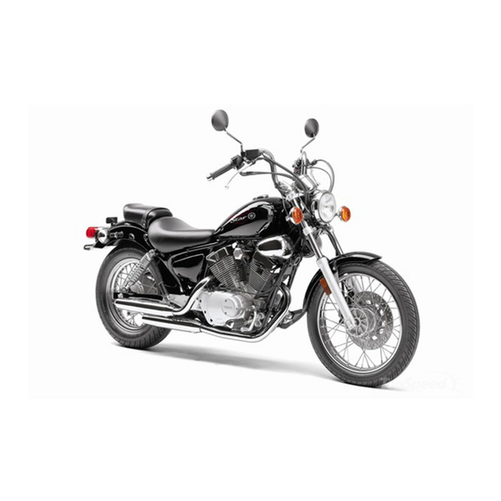
- Page 1 Read this manual carefully before operating this vehicle. OWNER’S MANUAL XV250A 1BE-28199-21...
- Page 2 EAU46090 Read this manual carefully before operating this vehicle. This manual should stay with this vehicle if it is sold.
- Page 3 EAU10102 Welcome to the Yamaha world of motorcycling! As the owner of the XV250A, you are benefiting from Yamaha’s vast experience and newest technology regarding the design and manufacture of high-quality products, which have earned Yamaha a reputation for dependability.
-
Page 4: Important Manual Information
IMPORTANT MANUAL INFORMATION EAU10132 Particularly important information is distinguished in this manual by the following notations: This is the safety alert symbol. It is used to alert you to potential personal injury hazards. Obey all safety messages that follow this symbol to avoid possible injury or death. - Page 5 IMPORTANT MANUAL INFORMATION EAU10200 XV250A OWNER’S MANUAL ©2010 by Yamaha Motor Co., Ltd. 1st edition, April 2010 All rights reserved. Any reprinting or unauthorized use without the written permission of Yamaha Motor Co., Ltd. is expressly prohibited. Printed in Japan.
-
Page 6: Table Of Contents
TABLE OF CONTENTS LOCATION OF IMPORTANT FOR YOUR SAFETY – Valve clearance ......7-15 LABELS ..........1-1 PRE-OPERATION CHECKS ..... 5-1 Tires ..........7-16 Spoke wheels ......7-18 SAFETY INFORMATION ....2-1 OPERATION AND IMPORTANT Adjusting the clutch lever free RIDING POINTS......... 6-1 play ........... - Page 7 TABLE OF CONTENTS Checking the wheel bearings ..7-29 Battery ..........7-30 Replacing the fuses ......7-31 Replacing the headlight bulb ..7-32 Replacing the tail/brake light bulb ...........7-33 Replacing a turn signal light bulb ...........7-34 Supporting the motorcycle ....7-35 Front wheel ........7-35 Rear wheel ........7-37 Troubleshooting ......7-39 Troubleshooting chart ....7-40 MOTORCYCLE CARE AND...
-
Page 8: Location Of Important Labels
Read and understand all of the labels on your vehicle. They contain important information for safe and proper operation of your vehicle. Never remove any labels from your vehicle. If a label becomes difficult to read or comes off, a replacement label is available from your Yamaha dealer. - Page 9 LOCATION OF IMPORTANT LABELS STATIONARY NOISE TEST INFORMATION TESTED 86 dB(A) 4000 r/min Cold tire normal pressure should be set as follows. SILENCING SYSTEM : YAMAHA IDENTIFICATION : 3DM-14711 1.75 2.00 1BE-2118G-00 2.00 2.25 3CK-21668-A1...
-
Page 10: Safety Information
SAFETY INFORMATION EAU10287 Safe Riding • Ride where other motorists can Perform the pre-operation checks each see you. Avoid riding in another time you use the vehicle to make sure it motorist’s blind spot. Be a Responsible Owner is in safe operating condition. Failure to Many accidents involve inexperi- As the vehicle’s owner, you are respon- inspect or maintain the vehicle properly... - Page 11 SAFETY INFORMATION due to excessive speed or under- This motorcycle is designed for on- A passenger should also observe cornering (insufficient lean angle road use only. It is not suitable for the above precautions. for the speed). off-road use. • Always obey the speed limit and Avoid Carbon Monoxide Poisoning never travel faster than warrant- Protective Apparel...
- Page 12 Yamaha accessories, which are avail- of the motorcycle is changed. To avoid to minimize imbalance or instabili- able only from a Yamaha dealer, have the possibility of an accident, use ex- been designed, tested, and approved treme caution when adding cargo or Shifting weights can create a sud- by Yamaha for use on your vehicle.
- Page 13 • Accessories fitted to the handle- Use caution when adding electri- genuine Yamaha accessories, recog- bar or the front fork area can cal accessories. If electrical acces- nize that some aftermarket accessories...
- Page 14 SAFETY INFORMATION Check that the fuel cock (if equipped) is in the “OFF” position and that there are no fuel leaks. Point the front wheel straight ahead on the trailer or in the truck bed, and choke it in a rail to pre- vent movement.
-
Page 15: Description
DESCRIPTION EAU10410 Left view 1. Headlight (page 7-32) 9. Fuel cock (page 4-7) 2. Steering lock (page 4-8) 10.Shift pedal (page 4-4) 3. Fuel tank (page 4-5) 4. Battery (page 7-30) 5. Fuses (page 7-31) 6. Helmet holder (page 4-9) 7. -
Page 16: Right View
DESCRIPTION EAU10420 Right view 1. Tail/brake light (page 7-33) 9. Owner’s tool kit (page 7-2) 2. Rear turn signal light (page 7-34) 10.Shock absorber assembly spring preload adjusting ring (page 4-10) 3. Rider seat (page 4-9) 4. Air filter element (page 7-12) 5. -
Page 17: Controls And Instruments
DESCRIPTION EAU10430 Controls and instruments 1. Clutch lever (page 4-4) 2. Left handlebar switches (page 4-2) 3. Speedometer unit (page 4-2) 4. Indicator lights (page 4-1) 5. Right handlebar switches (page 4-2) 6. Brake lever (page 4-4) 7. Throttle grip (page 7-15) 8. -
Page 18: Instrument And Control Functions
INSTRUMENT AND CONTROL FUNCTIONS EAU10450 EWA10072 EAU10981 Main switch Indicator lights WARNING Never turn the key to “OFF” while the vehicle is moving, otherwise the electrical systems will be switched off, which may result in loss of con- trol or an accident. 1. -
Page 19: Speedometer Unit
INSTRUMENT AND CONTROL FUNCTIONS EAU11090 EAU11630 EAU12348 High beam indicator light “HIGH Speedometer unit Handlebar switches BEAM” Left This indicator light comes on when the high beam of the headlight is switched 1. Odometer 2. Tripmeter 1. Pass switch “PASS” 3. - Page 20 INSTRUMENT AND CONTROL FUNCTIONS Right ter position. To cancel the turn signal The hazard lights are used in case of lights, push the switch in after it has re- an emergency or to warn other drivers turned to the center position. when your vehicle is stopped where it might be a traffic hazard.
-
Page 21: Clutch Lever
INSTRUMENT AND CONTROL FUNCTIONS EAU12820 EAU12871 EAU12890 Clutch lever Shift pedal Brake lever 1. Clutch lever 1. Shift pedal 1. Brake lever The clutch lever is located at the left The shift pedal is located on the left The brake lever is located at the right handlebar grip. -
Page 22: Brake Pedal
INSTRUMENT AND CONTROL FUNCTIONS EAU12941 EAU13041 Brake pedal Fuel tank cap The fuel tank cap cannot be closed un- less the key is in the lock. In addition, the key cannot be removed if the cap is not properly closed and locked. EWA11091 WARNING Make sure that the fuel tank cap is... -
Page 23: Fuel
EWA15151 filling when the fuel reaches the WARNING Your Yamaha engine has been de- bottom of the filler tube. Because Gasoline is poisonous and can signed to use regular unleaded gaso- fuel expands when it heats up, cause injury or death. -
Page 24: Fuel Cock
INSTRUMENT AND CONTROL FUNCTIONS EAU13581 Fuel cock This model is equipped with a negative pressure fuel cock. The fuel cock sup- plies fuel from the tank to the carburetor while also filtering it. The fuel cock lever positions are ex- plained as follows and shown in the il- lustrations. -
Page 25: Starter (Choke) Lever
INSTRUMENT AND CONTROL FUNCTIONS EAU13630 EAU13730 To unlock the steering Starter (choke) lever Steering lock 1. Open the steering lock cover, and then insert the key. 2. Push the key in, turn it 1/8 turn counterclockwise so that it moves out, and then release it. -
Page 26: Rider Seat
INSTRUMENT AND CONTROL FUNCTIONS EAU14220 EAU14282 Rider seat Helmet holder To remove the rider seat Remove the bolts, and then pull the rid- er seat off. 1. Projection 2. Seat holder 1. Helmet holder 2. Place the rider seat in the original 2. -
Page 27: Adjusting The Shock Absorber Assemblies
Yamaha’s ignition circuit cut-off sorber assembly in direction (a). To de- system has been designed to assist crease the spring preload and thereby... -
Page 28: Ignition Circuit Cut-Off System
INSTRUMENT AND CONTROL FUNCTIONS this system regularly and have a EAU48240 Ignition circuit cut-off system Yamaha dealer repair it if it does not The ignition circuit cut-off system (com- function properly. prising the sidestand switch, clutch switch and neutral switch) has the fol- lowing functions. - Page 29 WARNING With the engine turned off: 1. Move the sidestand down. If a malfunction is noted, have a Yamaha 2. Make sure that the engine stop switch is set to “RUN”. dealer check the system before riding. 3. Turn the key on.
-
Page 30: For Your Safety - Pre-Operation Checks
• If necessary, add recommended oil to specified level. 7-10 • Check vehicle for oil leakage. • Check operation. • If soft or spongy, have Yamaha dealer bleed hydraulic system. • Check lever free play. • Adjust if necessary. Front brake •... - Page 31 • Make sure that operation is smooth. • Check throttle grip free play. Throttle grip 7-15, 7-26 • If necessary, have Yamaha dealer adjust throttle grip free play and lubricate cable and grip housing. • Make sure that operation is smooth. Control cables 7-26 •...
- Page 32 FOR YOUR SAFETY – PRE-OPERATION CHECKS ITEM CHECKS PAGE • Check fluid level. Battery 7-30 • Fill with distilled water if necessary.
-
Page 33: Operation And Important Riding Points
NOTICE tral position. The neutral indicator light should come on. If not, ask a For maximum engine life, never ac- Yamaha dealer to check the elec- celerate hard when the engine is trical circuit. cold! 4. Turn the starter (choke) on and completely close the throttle. -
Page 34: Starting A Warm Engine
OPERATION AND IMPORTANT RIDING POINTS EAU16640 EAU16671 ECA10260 Starting a warm engine Shifting NOTICE Follow the same procedure as for start- Even with the transmission in ing a cold engine with the exception the neutral position, do not that the starter (choke) is not required coast for long periods of time when the engine is warm. -
Page 35: Tips For Reducing Fuel Consumption
Since the engine is brand new, do not soon as possible. immediately have a Yamaha dealer put an excessive load on it for the first Shift up swiftly, and avoid high en- check the vehicle. -
Page 36: Parking
OPERATION AND IMPORTANT RIDING POINTS EAU17213 Parking When parking, stop the engine, and then remove the key from the main switch. EWA10311 WARNING Since the engine and exhaust system can become very hot, park in a place where pedestri- ans or children are not likely to touch them and be burned. -
Page 37: Periodic Maintenance And Adjustment
– possibly leading to pending on the weather, terrain, geo- that is certified (if applicable). Yamaha death. See page 2-1 for more in- graphical location, and individual use, dealers are trained and equipped to... -
Page 38: Owner's Tool Kit
If you do not have the tools or experi- ence required for a particular job, have a Yamaha dealer perform it for you. -
Page 39: Periodic Maintenance Chart For The Emission Control System
From 50000 km (30000 mi), repeat the maintenance intervals starting from 10000 km (6000 mi). Items marked with an asterisk should be performed by a Yamaha dealer as they require special tools, data and technical skills. -
Page 40: General Maintenance And Lubrication Chart
PERIODIC MAINTENANCE AND ADJUSTMENT EAU1770C General maintenance and lubrication chart ODOMETER READING ANNUAL ITEM CHECK OR MAINTENANCE JOB 1000 km 10000 km 20000 km 30000 km 40000 km CHECK (600 mi) (6000 mi) (12000 mi) (18000 mi) (24000 mi) √ √... - Page 41 PERIODIC MAINTENANCE AND ADJUSTMENT ODOMETER READING ANNUAL ITEM CHECK OR MAINTENANCE JOB 1000 km 10000 km 20000 km 30000 km 40000 km CHECK (600 mi) (6000 mi) (12000 mi) (18000 mi) (24000 mi) • Check bearing for looseness or √ √...
- Page 42 PERIODIC MAINTENANCE AND ADJUSTMENT ODOMETER READING ANNUAL ITEM CHECK OR MAINTENANCE JOB 1000 km 10000 km 20000 km 30000 km 40000 km CHECK (600 mi) (6000 mi) (12000 mi) (18000 mi) (24000 mi) • Check operation. √ √ √ √ √...
- Page 43 PERIODIC MAINTENANCE AND ADJUSTMENT EAU18660 The air filter needs more frequent service if you are riding in unusually wet or dusty areas. Hydraulic brake service • Regularly check and, if necessary, correct the brake fluid level. • Every two years replace the internal components of the brake master cylinder and caliper, and change the brake fluid. •...
-
Page 44: Removing And Installing The Panel
PERIODIC MAINTENANCE AND ADJUSTMENT EAU18751 EAU19545 Removing and installing the Checking the spark plugs panel The spark plugs are important engine components, which are easy to check. The panel shown needs to be removed Since heat and deposits will cause any to perform some of the maintenance spark plug to slowly erode, the spark jobs described in this chapter. - Page 45 If any spark plug shows a distinctly dif- 1. Spark plug gap ferent color, the engine could be oper- ating improperly. Do not attempt to Spark plug gap: diagnose such problems yourself. In- 0.6–0.7 mm (0.024–0.028 in) stead, have a Yamaha dealer check the vehicle.
-
Page 46: Engine Oil And Oil Filter Element
PERIODIC MAINTENANCE AND ADJUSTMENT EAU42105 3. Remove the engine oil filler cap, Engine oil and oil filter ele- the engine oil drain bolt and its ment gasket to drain the oil from the The engine oil level should be checked crankcase. - Page 47 PERIODIC MAINTENANCE AND ADJUSTMENT Tightening torque: Engine oil drain bolt: Skip steps 4–6 if the oil filter element is 34 Nm (3.4 m·kgf, 25 ft·lbf) not being replaced. 8. Refill with the specified amount of 4. Remove the oil filter element cover the recommended engine oil, and by removing the screws.
-
Page 48: Cleaning The Air Filter Element
PERIODIC MAINTENANCE AND ADJUSTMENT fication of “CD” or oils of a high- EAU32738 Cleaning the air filter element er quality than specified. In The air filter element should be cleaned addition, do not use oils labeled or replaced at the intervals specified in “ENERGY CONSERVING II”... - Page 49 The air filter element should be wet but not dripping. Recommended oil: Yamaha foam air filter oil or other quality foam air filter oil 7. Pull the sponge material over the 1. Sponge material air filter element frame.
-
Page 50: Adjusting The Carburetor
[ECA10481] Yamaha dealer, who has the neces- periodic maintenance and lubrication 9. Install the air filter case cover by in- sary professional knowledge and expe- chart. -
Page 51: Checking The Throttle Grip Free Play
The valve clearance changes with use, resulting in improper air-fuel mixture and/or engine noise. To prevent this from occurring, the valve clearance must be adjusted by a Yamaha dealer at the intervals specified in the periodic maintenance and lubrication chart. 1. Throttle stop screw Engine idling speed: 1250–1350 r/min... -
Page 52: Tires
(i.e., when the temperature cause an accident. tact a Yamaha dealer immediately and of the tires equals the ambient have the tire replaced. temperature). Minimum tire tread depth (front and... - Page 53 After extensive tests, only the tires list- edge and experience. ed below have been approved for this It is not recommended to patch model by Yamaha Motor Co., Ltd. a punctured tube. If unavoid- able, however, patch the tube very carefully and replace it as soon as possible with a high- quality product.
-
Page 54: Spoke Wheels
4. Rubber cover age before each ride. If any dam- age is found, have a Yamaha The clutch lever free play should mea- dealer replace the wheel. Do not sure 10.0–15.0 mm (0.39–0.59 in) as attempt even the smallest repair to shown. -
Page 55: Adjusting The Brake Lever Free Play
If there is air in the hy- draulic system, have a Yamaha dealer bleed the system before 1. Locknut operating the motorcycle. Air in 2. -
Page 56: Adjusting The Brake Pedal Height And Free Play
2. Distance between brake pedal and footrest 3. Brake pedal free play 1. Locknut EWA10670 WARNING 2. Brake pedal height adjusting bolt It is advisable to have a Yamaha 3. Tighten the locknut. dealer make these adjustments. EWA11231 WARNING 1. Brake pedal free play adjusting nut... -
Page 57: Brake Light Switches
Brake light switches Checking the front brake pads obtained as described, have a and rear brake shoes Yamaha dealer make this ad- The front brake pads and the rear brake justment. shoes must be checked for wear at the After adjusting the brake pedal... -
Page 58: Checking The Brake Fluid Level
When checking the fluid level, brake fluid level goes down sud- the wear limit line, have a Yamaha make sure that the top of the mas- denly, have a Yamaha dealer dealer replace the brake shoes as a ter cylinder is level by turning the check the cause. -
Page 59: Changing The Brake Fluid
EAU22721 EAU22760 Changing the brake fluid Drive chain slack Have a Yamaha dealer change the The drive chain slack should be brake fluid at the intervals specified in checked before each ride and adjusted the TIP after the periodic maintenance if necessary. - Page 60 PERIODIC MAINTENANCE AND ADJUSTMENT 2. Remove the cotter pin from the 6. Insert a new cotter pin into the axle axle nut, and then loosen the axle nut, and then bend its ends as nut. shown. WARNING! Always use a 3.
-
Page 61: Cleaning And Lubricating The Drive Chain
PERIODIC MAINTENANCE AND ADJUSTMENT EWA10660 EAU23025 may contain substances that Cleaning and lubricating the WARNING could damage O-rings. drive chain After adjusting the brake pedal free [ECA11111] The drive chain must be cleaned and play, check the operation of the lubricated at the intervals specified in brake light. -
Page 62: Checking And Lubricating The Cables
Yamaha dealer at the intervals speci- ed if necessary. If a cable is damaged fied in the periodic maintenance chart. -
Page 63: Checking And Lubricating The Brake And Clutch Levers
PERIODIC MAINTENANCE AND ADJUSTMENT EAU23142 Recommended lubricant: Recommended lubricants: Checking and lubricating the Lithium-soap-based grease Brake lever: brake and clutch levers Silicone grease Clutch lever: Brake lever Lithium-soap-based grease Clutch lever The operation of the brake and clutch levers should be checked before each ride, and the lever pivots should be lu- bricated if necessary. -
Page 64: Checking And Lubricating The Sidestand
The swingarm pivots must be lubricat- intervals specified in the periodic main- ed by a Yamaha dealer at the intervals tenance and lubrication chart. specified in the periodic maintenance and lubrication chart. -
Page 65: Checking The Steering
Yamaha dealer check or re- [EWA10751] tion chart. If there is play in the wheel 2. Hold the lower ends of the front pair it. -
Page 66: Battery
PERIODIC MAINTENANCE AND ADJUSTMENT EAU50280 • EYES: Flush with water for 15 Battery minutes and seek prompt The electrolyte should be between the The battery is located under the rider medical attention. minimum and maximum level marks. seat. (See page 4-9.) Batteries produce explosive hy- A poorly maintained battery will corrode drogen gas. -
Page 67: Replacing The Fuses
PERIODIC MAINTENANCE AND ADJUSTMENT 3. Fully charge the battery before in- EAU23601 Replacing the fuses stallation. NOTICE: When install- ing the battery, be sure the key is turned to “OFF”, then con- nect the positive lead before connecting the negative lead. [ECA16840] 4. -
Page 68: Replacing The Headlight Bulb
4. If the fuse immediately blows Headlight bulb 1. Do not touch the glass part of the bulb. again, have a Yamaha dealer Do not touch the glass part of check the electrical system. the headlight bulb to keep it free 1. -
Page 69: Replacing The Tail/Brake Light Bulb
6. Install the headlight unit by install- 1. Remove the tail/brake light lens by ing the screws. removing the screws. 7. Have a Yamaha dealer adjust the headlight beam if necessary. 1. Headlight coupler 2. Headlight bulb cover 3. Remove the headlight bulb holder by turning it counterclockwise, and then remove the burnt-out bulb. -
Page 70: Replacing A Turn Signal Light Bulb
PERIODIC MAINTENANCE AND ADJUSTMENT EAU24212 Replacing a turn signal light bulb 1. Remove the turn signal lens by re- moving the screws. 1. Tail/brake light bulb 1. Turn signal light bulb 3. Insert a new bulb into the socket, 3. Insert a new bulb into the socket, push it in, and then turn it clock- push it in, and then turn it clock- wise until it stops. -
Page 71: Supporting The Motorcycle
PERIODIC MAINTENANCE AND ADJUSTMENT EAU24350 a jack either under each side of the EAU24360 Supporting the motorcycle Front wheel frame in front of the rear wheel or under Since this model is not equipped with a each side of the swingarm. centerstand, follow these precautions EAU24601 To remove the front wheel... - Page 72 PERIODIC MAINTENANCE AND ADJUSTMENT 1. Wheel axle 1. Speedometer gear unit 1. Speedometer gear unit 2. Front wheel axle pinch bolt 2. Retainer 2. Lift the wheel up between the fork 3. Speedometer cable 3. Lift the front wheel off the ground legs.
-
Page 73: Rear Wheel
PERIODIC MAINTENANCE AND ADJUSTMENT 7. While applying the front brake, EAU25080 3. Loosen the axle nut and the brake Rear wheel push down hard on the handlebars torque rod nut at the brake shoe several times to check if the front plate. - Page 74 PERIODIC MAINTENANCE AND ADJUSTMENT 7. Push the wheel forward, and then 6. Tighten the brake torque rod nut to remove the drive chain from the the specified torque. rear sprocket. Tightening torque: Brake torque rod nut: The drive chain does not need to be 23 Nm (2.3 m·kgf, 17 ft·lbf) disassembled in order to remove and 7.
-
Page 75: Troubleshooting
However, should your motorcycle require any repair, take it to a Yamaha dealer, whose skilled technicians have the necessary tools, experience, and know-how to service the motorcycle properly. -
Page 76: Troubleshooting Chart
Remove the spark plugs and check the electrodes. The engine does not start. Have a Yamaha dealer check the vehicle. Check the battery. 4. Battery The engine turns over The battery is good. -
Page 77: Motorcycle Care And Storage
Rust and corrosion can develop matte colored finished parts. Be Cleaning even if high-quality components are sure to consult a Yamaha dealer for ECA10772 advice on what products to use be- used. A rusty exhaust pipe may go un- NOTICE fore cleaning the vehicle. - Page 78 MOTORCYCLE CARE AND STORAGE off any detergent residue using Test the product on a small hid- plenty of water, as it is harmful den part of the windshield to Salt sprayed on roads in the winter may to plastic parts. make sure that it does not leave remain well into spring.
-
Page 79: Storage
WARNING ing it with a tarp, while it is still Contaminants on the brakes or tires Consult a Yamaha dealer for ad- wet, will allow water and humid- can cause loss of control. vice on what products to use. - Page 80 MOTORCYCLE CARE AND STORAGE 3. Drain the carburetor float cham- spark plug electrodes while °C (90 °F)]. For more information bers by loosening the drain bolts; turning the engine over. on storing the battery, see page this will prevent fuel deposits from 7-30.
-
Page 81: Specifications
SPECIFICATIONS Dimensions: Engine oil: Fuel reserve amount: 2.6 L (0.69 US gal, 0.57 Imp.gal) Overall length: Recommended brand: Carburetor: 2190 mm (86.2 in) YAMALUBE Type × quantity: Overall width: Type: 815 mm (32.1 in) SAE 10W-30, 10W-40, 10W-50, 15W-40, BDS26 x 1 Overall height: 20W-40 or 20W-50 Spark plug(s):... - Page 82 SPECIFICATIONS 3rd: Tire air pressure (measured on cold Operation: 29/23 (1.261) Right foot operation tires): 4th: Front suspension: Loading condition: 26/26 (1.000) Type: 0–90 kg (0–198 lb) 5th: Telescopic fork Front: 23/28 (0.821) Spring/shock absorber type: 175 kPa (1.75 kgf/cm², 25 psi) Chassis: Coil spring/oil damper Rear:...
- Page 83 SPECIFICATIONS Front turn signal light: 12 V, 21.0 W × 2 Rear turn signal light: 12 V, 21.0 W × 2 Meter lighting: 14 V, 3.0 W × 1 Neutral indicator light: 14 V, 3.0 W × 1 High beam indicator light: 12 V, 1.7 W ×...
-
Page 84: Consumer Information
Record the vehicle identification num- ber and model label information in the spaces provided below for assistance when ordering spare parts from a Yamaha dealer or for reference in case the vehicle is stolen. VEHICLE IDENTIFICATION NUMBER: 1. Vehicle identification number 1. -
Page 85: Motorcycle Noise Regulation (For Australia)
CONSUMER INFORMATION EAU26570 Motorcycle noise regulation (for Australia) TAMPERING WITH NOISE CON- TROL SYSTEM PROHIBITED: Owners are warned that the law may prohibit: a. The removal or rendering inopera- tive by any person other than for purposes of maintenance, repair or replacement, of any device or element of design incorporated into any new vehicle for the pur-... - Page 86 INDEX Pass switch ..........4-3 Air filter element, cleaning..... 7-12 Front fork, checking ......7-28 Fuel............4-6 Rider seat..........4-9 Fuel cock ..........4-7 Battery........... 7-30 Fuel consumption, tips for reducing..6-3 Brake and clutch levers, checking and Safety information ........2-1 Fuel tank cap ..........
- Page 87 INDEX Valve clearance ........7-15 Vehicle identification number....10-1 Wheel bearings, checking ....7-29 Wheel (front) ......... 7-35 Wheel (rear).......... 7-37 Wheels..........7-18...
- Page 90 YAMAHA MOTOR CO., LTD. PRINTED ON RECYCLED PAPER PRINTED IN JAPAN 2010.05-0.3×1 CR...