ASROCK N68-GS4 FX R2.0 User Manual
Hide thumbs
Also See for N68-GS4 FX R2.0:
- User manual (55 pages) ,
- Installation manual (45 pages) ,
- Installation manual (53 pages)

Related Manuals for ASROCK N68-GS4 FX R2.0


Summary of Contents for ASROCK N68-GS4 FX R2.0
-
Page 1: User Manual
N68-GS4/USB3 FX R2.0 N68-GS4 FX R2.0 User Manual Version 1.0 Published October 2015 Copyright©2015 ASRock INC. All rights reserved. 1 1 1 1 1... - Page 2 (including damages for loss of profits, loss of business, loss of data, interruption of business and the like), even if ASRock has been advised of the possibility of such damages arising from any defect or error in the manual or product.
-
Page 3: Table Of Contents
Contents Contents Contents Contents Contents 1 . 1 . 1 . 1 . Introduction Introduction Introduction ............Introduction ....................................5 5 5 5 5 Introduction ............Package Contents ..............5 Specifications ................6 Motherboard Layout ..............10 I/O Panel ..................12 2 . - Page 4 4 . 4 . 4 . 4 . Software Support Software Support Software Support Software Support ..........................................41 Software Support ........... Install Operating System ............41 Support CD Information .............. 41 4.2.1 Running Support CD ............41 4.2.2 Drivers Menu ..............
-
Page 5: Introduction Introduction
Introduction Introduction Introduction Thank you for purchasing ASRock N68-GS4/USB3 FX R2.0 / N68-GS4 FX R2.0 motherboard, a reliable motherboard produced under ASRock’s consistently stringent quality control. It delivers excellent performance with robust design conforming to ASRock’s commitment to quality and endurance. -
Page 6: Specifications
* To configure 7.1 CH HD Audio, it is required to use an HD front panel audio module and enable the multi-channel audio feature through the audio driver. - Supports Surge Protection (ASRock Full Spike Protection) - ELNA Audio Caps - Gigabit LAN 10/100/1000 Mb/s... - Page 7 - 1 x PS/2 Keyboard Port - 1 x Serial Port: COM1 - 1 x D-Sub Port - 2 x USB 2.0 Ports (Supports ESD Protection (ASRock Full Spike Protection)) - 2 x USB 3.0 Ports (Etron EJ188H) (PCIE GEN1) (Supports...
- Page 8 Certifications - FCC, CE, WHQL - ErP/EuP ready (ErP/EuP ready power supply is required) * For detailed product information, please visit our website: http://www.asrock.com WARNING Please realize that there is a certain risk involved with overclocking, including adjusting the setting in the BIOS, applying Untied Overclocking Technology, or using the third- party overclocking tools.
- Page 9 ASRock UCC (Unlock CPU Core) feature simplifies AMD CPU activation. As long as a simple switch of the BIOS option “ASRock UCC”, you can unlock the extra CPU core to enjoy an instant performance boost. When UCC feature is enabled, the dual-core or triple-core CPU will boost to the quad-...
-
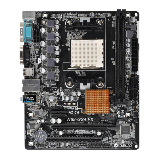
Page 10: Motherboard Layout
1.3 Motherboard Layout 1.3 Motherboard Layout 1.3 Motherboard Layout 1.3 Motherboard Layout 1.3 Motherboard Layout N68- N68- N68- N68- N68-GS4/USB3 FX R2.0: GS4/USB3 FX R2.0: GS4/USB3 FX R2.0: GS4/USB3 FX R2.0: GS4/USB3 FX R2.0: CPU_FAN1 USB 3.0 T: USB3 B: USB4 USB 2.0 Top: T: USB3... - Page 11 N68- N68- GS4 FX R2.0: GS4 FX R2.0: N68- N68- N68-GS4 FX R2.0: GS4 FX R2.0: GS4 FX R2.0: CPU_FAN1 USB 2.0 T: USB1 B: USB2 USB 2.0 Top: T: USB3 RJ-45 B: USB4 NVIDIA GeForce 7025 / BIOS nForce...
-
Page 12: I/O Panel
Line In (Light Blue)** D-Sub Port Front Speaker (Lime)** COM Port Microphone (Pink)** PS/2 Keyboard Port (Purple) N68- N68- N68-GS4 FX R2.0: GS4 FX R2.0: GS4 FX R2.0: GS4 FX R2.0: N68- N68- GS4 FX R2.0: PS/2 Mouse Port (Green) USB 2.0 Ports (USB34) - Page 13 * There are two LED next to the LAN port. Please refer to the table below for the LAN port LED indications. ACT/LINK SPEED LAN Port LED Indications Activity/Link LED SPEED LED Status Description Status Description No Activity 10Mbps connection Blinking Data Activity Orange...
-
Page 14: Installation Installation
2. 2. 2. 2. 2. Installation Installation Installation Installation Installation This is a Micro ATX form factor motherboard. Before you install the motherboard, study the configuration of your chassis to ensure that the motherboard fits into it. Pre-installation Precautions Pre-installation Precautions Pre-installation Precautions Pre-installation Precautions Pre-installation Precautions... -
Page 15: Cpu Installation
2.1 CPU Installation 2.1 CPU Installation 2.1 CPU Installation 2.1 CPU Installation 2.1 CPU Installation Step 1. Unlock the socket by lifting the lever up to a 90 angle. Step 2. Position the CPU directly above the socket such that the CPU corner with the golden triangle matches the socket corner with a small triangle. -
Page 16: Installation Of Memory Modules (Dimm)
2.3 Installation of Memor 2.3 Installation of Memor y Modules (DIMM) 2.3 Installation of Memor y Modules (DIMM) y Modules (DIMM) y Modules (DIMM) 2.3 Installation of Memor 2.3 Installation of Memor y Modules (DIMM) This motherboard provides two 240-pin DDR3 (Double Data Rate 3) DIMM slots, and supports Dual Channel Memory Technology. -
Page 17: Expansion Slots (Pci And Pci Express Slots)
2.4 Expansion Slots (PCI and PCI Express Slots) 2.4 Expansion Slots (PCI and PCI Express Slots) 2.4 Expansion Slots (PCI and PCI Express Slots) 2.4 Expansion Slots (PCI and PCI Express Slots) 2.4 Expansion Slots (PCI and PCI Express Slots) There is 1 PCI slot and 2 PCI Express slots on this motherboard. -
Page 18: Jumpers Setup
2.5 Jumpers Setup 2.5 Jumpers Setup 2.5 Jumpers Setup 2.5 Jumpers Setup 2.5 Jumpers Setup The illustration shows how jumpers are setup. When the jumper cap is placed on pins, the jumper is “Short”. If no jumper cap is placed on pins, the jumper is “Open”. -
Page 19: Onboard Headers And Connectors
2.6 Onboard Headers and Connectors 2.6 Onboard Headers and Connectors 2.6 Onboard Headers and Connectors 2.6 Onboard Headers and Connectors 2.6 Onboard Headers and Connectors Onboard headers and connectors are NOT jumpers. Do NOT place jumper caps over these headers and connectors. Placing jumper caps over the headers and connectors will cause permanent damage of the motherboard! •... - Page 20 Front Panel Audio Header This is an interface for the front PRESENCE# MIC_RET panel audio cable that allows (9-pin HD_AUDIO1) OUT_RET convenient connection and (see p.10 or 11, No. 17) control of audio devices. OUT2_L J_SENSE OUT2_R MIC2_R MIC2_L 1. High Definition Audio supports Jack Sensing, but the panel wire on the chassis must support HDA to function correctly.
- Page 21 Though this motherboard provides 4-Pin CPU fan (Quiet Fan) support, the 3-Pin CPU fan still can work successfully even without the fan speed control function. If you plan to connect the 3-Pin CPU fan to the CPU fan connector on this motherboard, please connect it to Pin 1-3.
-
Page 22: Bios Setup Utility Bios Setup Utility
3. 3. 3. 3. 3. BIOS SETUP UTILITY BIOS SETUP UTILITY BIOS SETUP UTILITY BIOS SETUP UTILITY BIOS SETUP UTILITY 3.1 Introduction 3.1 Introduction 3.1 Introduction 3.1 Introduction 3.1 Introduction This section explains how to use the BIOS SETUP UTILITY to configure your system. The SPI Memory on the motherboard stores the BIOS SETUP UTILITY. -
Page 23: Navigation Keys
3 . 1 . 2 3 . 1 . 2 Navigation Keys 3 . 1 . 2 Navigation Keys Navigation Keys Navigation Keys 3 . 1 . 2 3 . 1 . 2 Navigation Keys Please check the following table for the function description of each navigation key. - Page 24 [ :00:09] or [SHIFT-TAB] to System Date [Thu 08/10/2015] select a field. BIOS Version : N68-GS4 FX R2.0 P1.00 Use [+] or [-] to : AMD Athlon (tm) II X3 440 Processor Type configure system Time. Processor (64bit) : 3000MHz...
-
Page 25: Oc Tweaker Screen
ASRock UCC ASRock UCC (Unlock CPU Core) feature simplifies AMD CPU activation. As long as a simple switch of the BIOS option “ASRock UCC”, you can unlock the extra CPU core to enjoy an instant performance boost. When UCC feature is... - Page 26 Boot Failure Guard Count [Enabled] CPU/LDT Spread Spectrum [Enabled] PCIE Spread Spectrum [Enabled] SATA Spread Spectrum [Disabled] ASRock UCC [Auto] AMD Turbo Core Technology Select Screen AMD IO C-State Support [Enabled] Select Item CPU Active Core Control [Disabled] Enter Go to Sub Screen Processor Maximum Frequency x16.5 3300 MHZ...
- Page 27 Processor Voltage It allows you to adjust the value of processor voltage. However, for safety and system stability, it is not recommended to adjust the value of this item. NB Frequency Multiplier For safety and system stability, it is not recommended to adjust the value of this item.
- Page 28 Channel Interleaving This allows you to enable Channel Memory Interleaving. The default value is [Hash 2]. CAS Latency (CL) Use this item to adjust the means of memory accessing. The default value is [Auto]. TRCD Use this to adjust TRCD values. The default value is [Auto]. Use this to adjust TRP values.
-
Page 29: Advanced Screen
3 . 4 3 . 4 3 . 4 Advanced Screen Advanced Screen Advanced Screen 3 . 4 3 . 4 Advanced Screen Advanced Screen In this section, you may set the configurations for the following items: CPU Configuration, Chipset Configuration, ACPI Configuration, Storage Configuration, PCIPnP Configuration, SuperIO Configuration, and USB Configuration. -
Page 30: Cpu Configuration
3.4.1 3.4.1 CPU Configuration 3.4.1 CPU Configuration CPU Configuration CPU Configuration 3.4.1 3.4.1 CPU Configuration BIOS SETUP UTILITY Advanced CPU Configuration Enabling this function may reduce CPU voltage Cool ‘n’ Quiet [Auto] and memory freq., and Secure Virtual Machine [Enabled] lead to system Enhanced Halt State (C1E) [Disabled]... -
Page 31: Chipset Configuration
3 . 4 . 2 3 . 4 . 2 Chipset Configuration 3 . 4 . 2 Chipset Configuration Chipset Configuration Chipset Configuration 3 . 4 . 2 3 . 4 . 2 Chipset Configuration BIOS SETUP UTILITY Advanced Chipset Settings Auto/Enable/Disable Onboard HD Audio. -
Page 32: Acpi Configuration
3 . 4 . 3 3 . 4 . 3 ACPI Configuration 3 . 4 . 3 ACPI Configuration ACPI Configuration ACPI Configuration 3 . 4 . 3 3 . 4 . 3 ACPI Configuration BIOS SETUP UTILITY Advanced ACPI Settings Select auto-detect or disable the STR feature. -
Page 33: Storage Configuration
3.4.4 3.4.4 Storage Configuration 3.4.4 Storage Configuration Storage Configuration Storage Configuration 3.4.4 3.4.4 Storage Configuration BIOS SETUP UTILITY Advanced Options Storage Configuration Disabled Enabled Onboard SATA Controller [Enabled] SATA Operation Mode [IDE] SATAII_1 [Not Detected] SATAII_2 [Not Detected] [Not Detected] SATAII_3 SATAII_4 [Not Detected]... -
Page 34: Pcipnp Configuration
3.4.5 3.4.5 PCIPnP Configuration 3.4.5 PCIPnP Configuration PCIPnP Configuration PCIPnP Configuration 3.4.5 3.4.5 PCIPnP Configuration BIOS SETUP UTILITY Advanced Value in units of PCI Advanced PCI / PnP Settings clocks for PCI device latency timer PCI Latency Timer [32] register. PCI IDE BusMaster [Enabled] Select Screen... -
Page 35: Super Io Configuration
3 . 4 . 6 3 . 4 . 6 Super IO Configuration 3 . 4 . 6 Super IO Configuration Super IO Configuration Super IO Configuration 3 . 4 . 6 3 . 4 . 6 Super IO Configuration BIOS SETUP UTILITY Advanced Configure Super IO Chipset... -
Page 36: Usb Configuration
3 . 4 . 7 3 . 4 . 7 USB Configuration 3 . 4 . 7 USB Configuration USB Configuration USB Configuration 3 . 4 . 7 3 . 4 . 7 USB Configuration BIOS SETUP UTILITY Advanced USB Configuration To enable or disable the onboard USB controllers. -
Page 37: Hardware Health Event Monitoring Screen
3 . 5 3 . 5 3 . 5 Hardware Health Event Monitoring Screen Hardware Health Event Monitoring Screen Hardware Health Event Monitoring Screen 3 . 5 3 . 5 Hardware Health Event Monitoring Screen Hardware Health Event Monitoring Screen In this section, it allows you to monitor the status of the hardware on your system, including the parameters of the CPU temperature, motherboard temperature, CPU fan speed, chassis fan speed, and the critical voltage. -
Page 38: Boot Screen
Boot Screen Boot Screen Boot Screen Boot Screen Boot Screen In this section, it will display the available devices on your system for you to config- ure the boot settings and the boot priority. BIOS SETUP UTILITY Main OC Tweaker Advanced H/W Monitor Boot... -
Page 39: Security Screen
3 . 7 3 . 7 3 . 7 Security Screen Security Screen Security Screen 3 . 7 3 . 7 Security Screen Security Screen In this section, you may set or change the supervisor/user password for the system. For the user password, you may also clear it. BIOS SETUP UTILITY Main OC Tweaker... -
Page 40: Exit Screen
3 . 8 3 . 8 Exit Screen 3 . 8 Exit Screen Exit Screen Exit Screen 3 . 8 3 . 8 Exit Screen BIOS SETUP UTILITY Main OC Tweaker Advanced H/W Monitor Boot Security Exit Exit Options Exit system setup after saving the Save Changes and Exit changes. -
Page 41: Install Operating System
4.2.4 Contact Information Contact Information Contact Information Contact Information Contact Information If you need to contact ASRock or want to know more about ASRock, welcome to visit ASRock’s website at http://www.asrock.com; or you may contact your dealer for further information.