Fluke 5520a Operator's Manual
Multi-product
Hide thumbs
Also See for 5520a:
- Operator's manual (420 pages) ,
- Service manual (254 pages) ,
- Programmer's manual (46 pages)

Related Manuals for Fluke 5520a


Summary of Contents for Fluke 5520a
- Page 1 ® 5520A Multi-Product Operators Guide PN 688754 February 1998 Rev. 1, 4/98 © 1998 Fluke Corporation, Inc. All rights reserved. Printed in USA. All product names are trademarks of their respective companies...
-
Page 3: Table Of Contents
Contents What is in this Guide? ..........3 Safety Information..........3 How to Contact Fluke ...........7 Unpacking and Inspecting ........7 Replacing the Fuse ..........8 Selecting Line Voltage ........10 Connecting to Line Power ........10 Cooling Considerations ........11 Front Panel ............12 Rear Panel............18 Turning on the Calibrator ........21 Warming up the Calibrator .........22... - Page 4 Dual DC Voltage Output .........51 Dual AC Voltage Output........53 Resistance Output ..........57 Capacitance Output ...........59 Temperature Simulation (TC)......60 Temperature Simulation (RTD) .......63 Measuring a Thermocouple Output.....65 Measuring Pressure ...........68 Waveforms............72 Sinewave (sine) ..........72 Trianglewave (tri)..........72 Squarewave (square)........73 Truncated Sinewave (truncs) ......73 Setting Harmonics..........74 Adjusting the Phase ...........75 Setting a Phase Angle ........77...
-
Page 5: What Is In This Guide
What is in this Guide? The 5520A Operator Guide is a condensation of information in the 5520A Operators Manual (PN 688739). For complete descriptions of the Calibrator’s features, functions, and operating procedures, refer to the Operators Manual . Safety Information Warning The Calibrator can supply lethal voltages. -
Page 6: Ac Power Source
• For 100 V or 120 V operation, use a 5 A/250 V time delay fuse (Fluke PN 109215). • For 200 V or 240 V operation, use a 2.5 A/250 V time delay fuse (Fluke PN 851931). - Page 7 Safety Information (cont) Grounding the Calibrator The Calibrator uses controlled overvoltage techniques that require the Calibrator to be grounded whenever normal mode or common mode ac voltages or transient voltages may occur. The enclosure must be grounded through the grounding conductor of the power cord, or through the rear panel CHASSIS GROUND binding post.
- Page 8 Normal calibration is accomplished with the cover closed. Access procedures and the warnings for such procedures are contained in the 5520A Service Manual . Service procedures are for qualified service personnel only. Do Not Attempt to Operate if Protection...
-
Page 9: How To Contact Fluke
How to Contact Fluke To order accessories, receive operating assistance, or get the location of the nearest Fluke distributor or Service Center, call: 1-800-44FLUKE (1-800-443-5853) in U.S.A. and Canada +31-402-678-200 in Europe +81-3-3434-0181 Japan +65-*-276-6196 Singapore +1-425-356-5500 from other countries... -
Page 10: Replacing The Fuse
688770 5520A Operators Guide 688777 (Simplified Chinese) − Certificate of Calibration *See Chapter 2 of the 5520A Operator’s Manual for available types Replacing the Fuse Caution To avoid damage to the Calibrator, verify that the correct fuse is installed for the selected line voltage. For 100 V and 120 V, use 5 A/250 V time delay;... - Page 11 Line voltage indicator Changing line fuse Changing line voltage oe01f.eps...
-
Page 12: Selecting Line Voltage
If you need a different plug, refer to Chapter 2 of the 5520A Operators Manual for a list and illustrations of available plugs. After you verify that the line voltage is set correctly... -
Page 13: Cooling Considerations
Cooling Considerations Warning To avoid risk of injury, never operate or power the Calibrator without the fan filter in place. Caution Damage caused by overheating may occur if the area around the air intake is restricted, the intake air is too warm, or the air filter becomes clogged. -
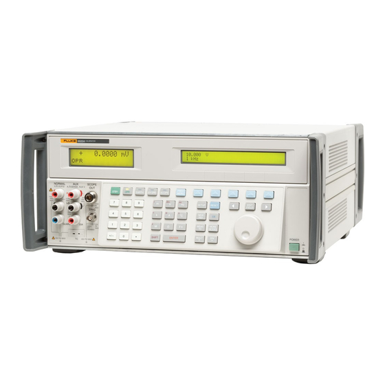
Page 14: Front Panel
Front Panel The front panel provides all controls, displays, indicators, and terminals. 5520A CALIBRATOR NORMAL SCOPE V, , ,RTD A, -SENSE, AUX V PREV STBY EARTH SCOPE EXGRD MENU µ EDIT SETUP RESET FIELD TRIG °F °C MEAS MORE GUARD... - Page 15 Front Panel (cont) Places the Calibrator in the operate mode and lights the indicator on the key. Opens and closes a connection between the NORMAL LO terminal and earth ground. When the indicator is lit, the connection is closed. Activates or deactivates an oscilloscope calibration option if one is installed.
- Page 16 Displays the setup menu in the control display. Setup options can be selected using the softkeys. Aborts the current operating state of the 5520A and returns it to the power-up default state, except during remote control. Clears a partially completed keypad entry from the Control Display.
- Page 17 Changes the output to 10x the reference value (not necessarily the present output value). Enables the thermocouple (TC) input connection and causes the 5520A to compute a temperature based on the input. V A Q H F C Select the Calibrator function. Some keys...
- Page 18 Front Panel (cont) 5520A CALIBRATOR NORMAL SCOPE V, , ,RTD A, -SENSE, AUX V PREV STBY EARTH SCOPE EXGRD MENU µ EDIT SETUP RESET FIELD TRIG °F °C MEAS MORE GUARD MODES POWER MULT • SHIFT ENTER ÷ 20V PK MAX 20V PK MAX oe04f.eps...
- Page 19 Front Panel (cont) SCOPE OUT The output connector for oscilloscope calibration. The input/output jack for thermocouple simulation during temperature meter calibration, and thermocouple measurements. The high terminal for sourcing the high current range (3A to 20A). The source of ac and dc current outputs, the second voltage output in dual voltage modes, and ohms sense for two-wire and four-wire compensated resistance and capacitance...
-
Page 20: Rear Panel
Connector used for transmitting/receiving serial data between the Calibrator and a Unit Under Test (UUT). This is also the connector for Fluke 700 Series Pressure Modules. SERIAL 1 FROM HOST Connector used for remote control of the Calibrator with a host, printer, or terminal. - Page 21 Rear Panel (cont) 10 MHz IN Connector for applying an optional external clock signal to the 5520A. This replaces the normal internal 10 MHz clock signal in the 5520A. Frequency accuracy of the 5520A is governed by the frequency accuracy of the clock signal internal or external.
- Page 22 Rear Panel (cont) Warning To avoid shock hazard, connect the factory supplied three- conductor line power cord to a properly grounded power outlet. Do not use a two-conductor adapter or extension cord; this will break the protective ground connection. Use the rear-panel ground terminal for a protective grounding wire if there is any question as to Calibrator earth...
-
Page 23: Turning On The Calibrator
Turning on the Calibrator Warning The Calibrator is capable of supplying lethal voltages. Do not make connections to the output terminals when any voltage is present. Placing the Calibrator in standby may not be enough to avoid shock hazard, since key could be pressed accidentally. -
Page 24: Warming Up The Calibrator
When the Calibrator is powered up, it displays “Starting Up...” (see below) and it completes a self-test routine. If a self-test fails, the Control Display identifies an error code. oe06f.eps After self-test, the Control Display shows the reset condition (below). oe07f.eps Warming up the Calibrator Allow the Calibrator to warm-up for at least 30... -
Page 25: Using The Softkeys
Using the Softkeys The five keys to the right of the P(previous menu) key are softkeys. A “softkey” is an unlabeled key that accesses a menu or menu tree with multiply functions and operations. A softkey’s functional or operational status is shown directly above it on the Control Display. -
Page 26: Instrument Setup Menu
Instrument Setup Menu Press INSTMT SETUP in the setup menu to open the instrument setup menu. oe09f.eps OTHER SETUP opens a menu to select the temperature standard, set the clock, and change the power-up defaults for displayed error units and safety timeout period for an oscilloscope option test. -
Page 27: Utility Functions Menu
Calibrator as well as the user- entered report string. Format EEPROM Menu Caution Use with extreme care! The FORMAT NV MEM (format nonvolatile memory) softkeys permanently erase calibration constants. Pressing ALL or CAL invalidates the state of calibration of the 5520A. - Page 28 Press FORMAT NV MEM in the utility functions menu to open the following menu: oe11f.eps ALL replaces the contents of the EEPROM with factory defaults. The rear panel CALIBRATION switch must be in the ENABLE position. CAL replaces all calibration constants with factory defaults.
- Page 29 Factory Defaults User report string cleared (RPT_STR string) >0.1% Error units SC-600 option overload 10 seconds test safety timeout Temperature standard its-90 Host interface gpib (IEEE-488) UUT serial interface 8 bits, 1 stop bit, xon/xoff, parity none, 9600 baud Host serial interface term, 8 bits, 1 stop bit, xon/xoff, parity none, 9600 baud,...
- Page 30 Factory Defaults (cont) Thermocouple type Phase reference 0.00 degrees 10 MHz reference clock internal ±20.5 A Current limits ±1000 V Voltage Limits Remote Command Defaults SRQSTR SRQ: %02x %02x %04x %04x *PUD string cleared Note: Output Display and Control Display, respectively.
-
Page 31: Zeroing The Calibrator
Zeroing the Calibrator To meet specifications, zero the Calibrator every 7 days, or when the Calibrator ambient temperature changes by more than 5 °C. Choose from complete Calibrator zeroing (ZERO) or ohms-only zeroing (OHMS ZERO). For the tightest ohms specifications, zero the ohms function every 12 hours, or whenever the ambient temperature has changed more than ±1 °C. -
Page 32: Operate And Standby
Press ZERO for complete Calibrator zeroing or OHMS ZERO for ohms-only zeroing. After zeroing routine is complete (several minutes), press R. Operate and Standby To enable the operate mode, press O. To place the Calibrator in standby, press Y. The Calibrator goes into the standby if: •... -
Page 33: Using The Earth And Exgrd Keys
Earth The 5520A Calibrator front panel NORMAL LO terminal is normally isolated from earth (chassis) ground. When it is desired to make a connection between the NORMAL LO terminal and earth ground, press the Z key, lighting the key... -
Page 34: External Guard
UUT is isolated from earth ground. There must, however, be a safety ground for the 5520A. See “Connecting to Line Power” in Chapter 2. When enabled by the sourced output, a softkey LOs appears, which allows you to tie or open an internal connection between the NORMAL LO terminal and AUX LO terminal. -
Page 35: Four-Wire And Two-Wire Connections
This is the default condition whenever an ohms or capacitance output is made, following an output that was not ohms or capacitance. Cable Connection Diagrams 5520A CALIBRATOR TRUE RMS MULTIMETER MIN MAX RANGE... - Page 36 DC Voltage/AC Voltage TRUE RMS MULTIMETER 5520A CALIBRATOR MIN MAX RANGE HOLD PEAK MIN MAX NORMAL SCOPE V, , ,RTD A, -SENSE, AUX V µ TRIG mA µA GUARD 20V PK MAX 20V PK MAX oe17f.eps DC Current/AC Current...
- Page 37 5520A CALIBRATOR TRUE RMS MULTIMETER MIN MAX RANGE HOLD PEAK MIN MAX NORMAL SCOPE V, , ,RTD A, -SENSE, AUX V µ TRIG COM V mA A GUARD 20V PK MAX 20V PK MAX 5520A oe19f.eps Ohms (2-Wire Comp) 5520A...
- Page 38 5520A CALIBRATOR TRUE RMS MULTIMETER MIN MAX RANGE HOLD PEAK MIN MAX NORMAL SCOPE V, , ,RTD A, -SENSE, AUX V µ TRIG COM V mA A GUARD 20V PK MAX 20V PK MAX oe21f.eps Capacitance (2-Wire Comp) 5520A CALIBRATOR...
- Page 39 5520A CALIBRATOR CHART RECORDER INPUT NORMAL SCOPE V, , ,RTD A, -SENSE, AUX V TRIG GUARD 20V PK MAX 20V PK MAX oe24f.eps Temperature (RTD) 5520A CALIBRATOR K/J THERMOMETER ON/OFF NORMAL SCOPE V, , ,RTD A, -SENSE, AUX V HOLD...
-
Page 40: Rms Versus P-P Waveforms
RMS Versus p-p Waveforms Sinewave outputs are in rms, while the trianglewave, squarewave, and truncated sinewave outputs are in p-p. The relationship between p-p and rms for the non-sinewave types are as follows: • Squarewave p-p x 0.5000000 = rms •... -
Page 41: Setting Outputs
Setting Outputs DC Voltage Output To set a dc voltage output at the Calibrator NORMAL terminals: 1. Press R to clear the Calibrator output. 2. Connect to the UUT. 3. Set the UUT to measure dc voltage. 4. Enter the desired voltage output (up to 7 digits). -
Page 42: Ac Voltage Output
AC Voltage Output To set ac voltage output in volts or as a power output in dBm (referenced to a selectable load impedance) at the Calibrator NORMAL terminals: 1. Press R to clear the Calibrator output. 2. Connect to the UUT. 3. - Page 43 φ & REF MENUS opens a menu to control the phase relationship between the output and that of a master 5520A synchronized using the 10 MHz IN input. WAVE (waveform) selects one of four different types of waveforms.
-
Page 44: Dc Current Output
DC Current Output To set dc a current output at the Calibrator AUX or 20A terminals: Press R to clear the Calibrator output. Connect to the UUT. Set the UUT to measure dc current. Enter the desired current output (up to 6 digits). -
Page 45: Ac Current Output
AC Current Output To set an ac current output at Calibrator AUX or 20A terminals: 1. Press R to clear the Calibrator output. 2. Connect to the UUT. 3. Set the UUT to measure ac current. 4. Enter the desired current output (up to 6 digits). 5. - Page 46 φ & REF MENUS opens a menu to control a phase relationship between the output and that of a master 5520A synchronized using the 10 MHz IN input. LCOMP turns inductive compensation on and off. Inductive compensation is available for frequencies up to 1 kHz at outputs up to 239.999...
-
Page 47: Dc Power Output
DC Power Output Note Tie the NORMAL LO and AUX LO terminals together at the UUT or at the Calibrator, via the “LO”s “tied” softkey. To set dc a voltage at Calibrator NORMAL terminals and a dc current on AUX or 20A terminals: 1. - Page 48 12. The Control Display shows entered value. For example, 123.4567 mV and 234.567 mA. oe36f.eps 13. Press E. oe37f.eps 14. Press O to activate the Calibrator output. (Enter voltage or current and then a watts entry value using bA. The remaining volts or current value is calculated and displayed.) oe80f.eps I OUT selects AUX or 20A terminals.
-
Page 49: Ac Power Output
AC Power Output Note Tie the NORMAL LO and AUX LO terminals together at the UUT or at the Calibrator, via the “LO”s “tied” softkey. For optimum phase performance, tie the LO terminals at the UUT. At current levels ± 2.2 A, tie the terminals at the UUT using heavy gage wire <10 m Ω... - Page 50 11. Press a multiplier key, if necessary. 12. Press H. 13. Control Display shows entered value. For example, 123.456 mV, 234.567 mA, and 1.1234 kHz. oe38f.eps 14. Press E. oe39f.eps 15. Press O to activate the Calibrator output.
- Page 51 oe40f.eps...
- Page 52 NORMAL LO and AUX LO terminals. φ & REF MENUS opens a menu to control a phase relationship between the output and that of a master 5520A synchronized using the 10 MHz IN input, and a phase difference between NORMAL and AUX outputs.
-
Page 53: Dual Dc Voltage Output
Dual DC Voltage Output Note Tie the NORMAL LO and AUX LO terminals together at the UUT or at the Calibrator, via the “LO”s “tied” softkey. To set dual dc voltages at Calibrator NORMAL and AUX terminals: 1. Press R to clear the Calibrator output. 2. - Page 54 13. Press E. 14. Press O to activate the Calibrator output. oe43f.eps “LO”s ties or opens a connection between front panel NORMAL LO and AUX LO terminals.
-
Page 55: Dual Ac Voltage Output
Dual AC Voltage Output Note Tie the NORMAL LO and AUX LO terminals together at the UUT or at the Calibrator, via the “LO”s tied softkey. Selecting voltage in units of dBm is not allowed in dual ac voltage mode. To set dual ac voltages at Calibrator NORMAL and AUX terminals: 1. - Page 56 11. Press a multiplier key, if necessary. 12. Press H. 13. The Control Display shows entries. For example, 123.456 mV, 234.567 mV at 1.1234 kHz. oe44f.eps 14. Press E. oe45f.eps...
- Page 57 oe46f.eps...
- Page 58 NORMAL LO and AUX LO terminals. φ & REF MENUS opens a menu to control a phase relationship between the output and that of a master 5520A synchronized using the 10 MHz IN input, and a phase difference between NORMAL and AUX outputs.
-
Page 59: Resistance Output
Resistance Output To set synthesized resistance output at Calibrator NORMAL terminals: 1. Press R to clear the Calibrator output. 2. Connect to the UUT. Note Terminal connections from Calibrator to UUT must be LO to LO and HI to HI. 3. - Page 60 9. Press O to activate the Calibrator output. oe49f.eps OHMS ZERO press to remove offests in the internal circuitry for the ohms function. Allow several minutes. COMP for <110 kΩ only, applies four-wire, two- wire or compensation off.
-
Page 61: Capacitance Output
Capacitance Output To set synthesized capacitance output at Calibrator NORMAL terminals: 1. Press R to clear the Calibrator output. 2. Connect to the UUT. Note Since this is a synthesized output, the terminal connections from the Calibrator to the UUT must be LO to LO and HI to HI. 3. -
Page 62: Temperature Simulation (Tc)
9. Press O to activate the Calibrator output. oe52f.eps COMP (Compensation) applies two-wire compensation or turns compensation off for capacitance of 110 nF and above. This feature cancels out lead resistance, NOT capacitance. Temperature Simulation (TC) Note Make sure the thermocouple wire and plug are not affected by extraneous temperature sources. - Page 63 6. The Control Display shows the entered value. For example, 123.456 °C. oe53f.eps 7. Press E. oe54f.eps 8. Press O to activate the Calibrator output. Note The temperature is cleared to 0 ° C (32 ° F) if you change between tc and rtd, or change the type of thermocouple (except a B-type thermocouple, which starts at 600 °...
- Page 64 oe55f.eps...
-
Page 65: Temperature Simulation (Rtd)
Out@TC terminal displays dc voltage at TC terminals. TC MENUS opens submenus for thermocouple outputs. OUTPUT selects the temperature device: thermocouple (tc) or resistance temperature detector (rtd). TYPE selects the thermocouple type to simulate. UNITS selects °C or °F temperature unit. REF SRC selects intrnl (Internal) or extrnl (External) reference source. - Page 66 7. Press E. oe54f.eps 8. Press O to activate the Calibrator output. Note The temperature is cleared to 0 ° C (32 ° F) if you change between tc and rtd, or change the type of rtd. oe58f.eps Output @ NORMALdisplays location of output terminals (always NORMAL).
-
Page 67: Measuring A Thermocouple Output
Measuring a Thermocouple Output To measure the output of a thermocouple connected to the Calibrator TC connector: 1. Press R to clear the Calibrator output. 2. Connect a thermocouple to TC connector. Note Use thermocouple wire and miniconnectors that match the type of thermocouple. 3. - Page 68 oe59f.eps...
- Page 69 4. The measured temperature is in Output Display. A lower-case m blinks during a measurement. oe60f.eps Meas@TC terminal displays dc voltage at TC terminals. TC MENUS opens submenus supporting thermocouple outputs. Open TCD Turns the “open thermocouple detect” feature on or off. UNITS selects °C or °F temperature units.
-
Page 70: Measuring Pressure
Measuring Pressure The 5520A can be used as a pressure Calibrator when you use it with the following accessories: To measure pressure: • Fluke 700-Series Pressure Module • Model 700PCK Pressure Calibration Kit (necessary because it provides the interface module) •... - Page 71 Connect the interface unit to the line power adapter. Plug the line power cord into line power. Press the m key on the 5520A. This activates pressure mode. The Output Display shows the pressure value measured by the pressure module. The...
- Page 72 10. If you are using an absolute-pressure type module (Model Number starts with “700PA”) zero the pressure module as follows: Vent the module to atmosphere. Press the SET OFFSET softkey. Enter the ambient atmospheric pressure in the units currently displayed. Note Do not rely on airport pressure reports.
- Page 73 TO AVOID PHYSICAL INJURY, INSURE THAT THE FILTER IS PROPERLY INSTALLED BEFORE ENERGIZING INSTRUMENT -UNPLUG INSTRUMENT CHASSIS P - P GROUND -REMOVE FILTER -FLUSH WITH SOAPY WATER -DRY BEFORE REINSTALLATION WARNING: TO AVOID ELECTRIC SHOCK GROUNDING CONNECTOR IN POWER CORD MUST BE CONNECTED 5520A Rear Panel oe77f.eps...
-
Page 74: Waveforms
Waveforms For ac voltage, ac current, dual ac voltage, and ac power, select among sine, tri, square, or truncs waveforms. Sinewave (sine) A sinewave is present on Calibrator outputs. Variables are amplitude, frequency, and dc offset voltage. rms (70% pk) Period oe61f.eps Sinewave... -
Page 75: Squarewave (Square)
Squarewave (square) A squarewave is present on Calibrator outputs. Variables are duty cycle, amplitude, frequency, and dc offset voltage. Period Decrease Duty Cycle Increase Duty Cycle oe63f.eps Squarewave and Duty Cycle Truncated Sinewave (truncs) A truncated sinewave is present on Calibrator outputs. -
Page 76: Setting Harmonics
Setting Harmonics To source two signals with adjustable harmonic difference for dual ac voltages or ac power (sinewaves only), perform the procedure below. Fundamentals can be configured on either NORMAL or AUX terminals. 1. Press WAVE MENUS to open waveform menu. 2. -
Page 77: Adjusting The Phase
3. Press FUNDMTL to select NORMAL or AUX terminals for fundamental. 4. Press HARMNIC to enter desired harmonic (1 to 50). For example, 7th harmonic. Press oe66f.eps 5. Press Pone or more times to return to previous menus. Adjusting the Phase To set a phase difference between outputs in dual ac voltage and ac power output modes:... - Page 78 oe67f.eps...
-
Page 79: Setting A Phase Angle
Setting a Phase Angle To set a phase shift in degrees for dual ac voltage or ac power output: 1. Press WAVE MENUS to open waveform menu. 2. Press PHASE to open phase entry menu. 3. Enter the desired phase angle (up to 5 digits). 4. -
Page 80: Setting A Dc Offset
5. Press PF to toggle a leading (lead) or lagging (lag) power factor. For example, a leading power factor of .678. Press E. oe69f.eps 6. Press Pone or more times to return to previous menus. Setting a DC Offset To set a dc offset for single ac voltage outputs: oe70f.eps 1. -
Page 81: Editing And Error Output Settings
4. Press Pone or more times to return to previous menus. Editing and Error Output Settings Use the Edit Field knob and L, W, and ekeys to edit outputs. Multiply Xand divide Dkeys edit output by decades. Keys That Exit Error Mode Keys Action Returns to the previous... -
Page 82: Editing The Output Setting
Editing the Output Setting Turn the Edit Field knob clockwise to increase the output value or counter-clockwise to decrease the output value. To select a higher order digit, use the key Lor W.. The output digit selected for editing is underlined. oe72f.eps Displaying the Output Error When you edit the output value, the Control... -
Page 83: Multiplying And Dividing
Multiplying and Dividing Press X to multiply the output by 10. Press D to divide the output by 10. If multiplied output exceeds 33 V, the Calibrator is placed in STBY (Standby). Setting Voltage and Current Limits Output limits help prevent accidental damage to UUTs from overcurrent or overvoltage. -
Page 84: Synchronizing The Calibrator Using 10 Mhz In/Out
Calibrators to calibrate a three-phase power meter. Another use for the 10 MHz IN reference input is to improve the frequency performance of the 5520A by injecting a reference 10 MHz clock signal. That application is described next. -
Page 85: Using An External 10 Mhz Clock
Using an External 10 MHz Clock The Calibrator uses an internal 10 MHz clock signal as a reference for all ac functions. Although this internal clock is very accurate and stable, you may have a lab standard that you want to have govern the frequency performance of the Calibrator. -
Page 86: Sourcing Current With Parallel-Connected 5520As
On 5520A #2, select external reference, set the output to the desired ac current level, and activate output mode. On 5520A #1, set the output to the desired ac current level, and activate output mode. This sends a sync pulse to 5520A #2. Now both 5520As are sourcing current in phase, in parallel. -
Page 87: Performance Verification
5520A are provided in the 5520A Service Manual . Refer to “Performance Verification” in Chapter 7 of the 5520A Operators Manual for a list of required equipment. If a specific instrument is not available, another instrument that assures a 4:1 Test... -
Page 88: Internal Fuses
Calibrator. These fuses cannot be replaced by the operator. For fuse locations and descriptions, refer to “Internal Fuse Replacement” in Chapter 7 of the 5520A Operators Manual . For instructions on replacing an internal fuse, refer to the 5520A Service Manual .