Advertisement
Quick Links
Table of Contents
Specification..................................... 1
Parts List .......................................... 2,3
Adjustment....................................... 4
Note On Safety................................. 4
Case Outlines................................... 5
PCB Assembly ................................. 5,6,7,8
Schematic Diagram.......................... 9,10,11,12
Specification
Continuous Power Output
Total Harmonic Distortion
Intermodulation Distortion
Frequency Response
Damping Factor
Speaker Impedance
Signal to Noise Ratio,
Input Impedance/Sensitivity
Power Requirement
Power Consumption
Dimensions (W x H x D)
Weight (net)
SHINSEN-BLD. 4F 10-10 SHINSEN-CHO, SHIBUYA-KU,
TOKYO 150-0045, JAPAN
Quality Uncompromised
(20-20 kHz < 0.03%, 8 ohms)
(20-20 kHz, 8 ohms)
(60 Hz: 7 kHz, 4:1)
(± 0.5dB)
(20-20K Hz, 8 ohms)
(IHF A network)
®
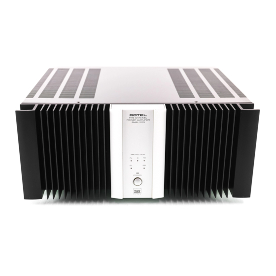
RMB-1075
100 Watts/ch
< 0.03%
< 0.03%
10Hz-80kHz
180
4 ohms minimum
115 dB
27 k Ohoms/1.0 volt
115 volts 60 Hz or
230 volts 50 Hz
800 watts
440 x 139 x 396mm
17
x 5
3/8"
15.5 kg, 34.1 Lb.
x 15
1/2"
5/8"
Serial. NO.
Begining
Y-336A-00125C/S-S
Advertisement

Summary of Contents for Rotel RMB-1075
-
Page 1: Table Of Contents
Quality Uncompromised ® RMB-1075 Table of Contents Specification........1 Parts List .......... 2,3 Adjustment........4 Note On Safety......... 4 Case Outlines........5 PCB Assembly ......... 5,6,7,8 Schematic Diagram......9,10,11,12 Specification Continuous Power Output (20-20 kHz < 0.03%, 8 ohms) 100 Watts/ch... -
Page 2: Parts List
Parts List-1 SYMBOL PARTS NO. DESCRIPTION SYMBOL PARTS NO. DESCRIPTION X-1267-01,02 PCB ASSY C101 041 50BGF4R7M CAPACITOR ELEC.50V4.7UF R137 053 CR14-822J-A RESISTOR CARBON 8.2K C102 044 TFKP2-2A681H CAPACITOR FILM 100V680PF R138 054 TMFR4033K RESISTOR METAL 1% 33K C103 044 FSC160V221H CAPACITOR STYROL 160V220PF R139 053 CR14-392J-A... - Page 3 Parts List-2 SYMBOL PARTS NO. DESCRIPTION SYMBOL PARTS NO. DESCRIPTION OTHERS RY101 063 OZ-SH-112LM ※ RELAY (POWER) 011 FP-529 FRONT PANEL ASSY T101 022 T-1075N01 ※ SUB TRANSFORMER 012 RV4-09A00 PUSH KNOB 14F 069 C-3417A FUSE CLIP 014 TE3-08A00 UPPER COVER 015 RP-380 REAR CHASSIS X-1291-02 PCB ASSEMBLY...
-
Page 4: Adjustment
Adjustment Instruments : DC milli–voltmeter Notes : Prior to Bias Adjustment, run about 5minutes with rated output(8ohms) and warm up Power Transistor and Heat Sink. Set input off. Coupling Step Location Adjust Adjust for TP 1 X-1267-01 PCB VR101 TP 2 X-1267-01 PCB VR201 TP 3... -
Page 5: Case Outlines
PCB Assembly Case Outlines 2SA1016K 2SA1376A 2SB631K 2SC536K 2SA1209 2SC2362K 2SD1953 2SC3478A 2SD600K 2SA1667 2SC3708 2SC2911 2SC4381 2SA1492 PC817B NJM4558DD 2SC3856... - Page 6 PCB Assembly...
-
Page 7: Schematic Diagram
Schematic Diagram... - Page 8 Schematic Diagram...


