Comelit 6601W Technical Manual
Icona sbc colour monitor
Hide thumbs
Also See for 6601W:
- Technical manual (24 pages) ,
- User manual (18 pages) ,
- Technical manual (17 pages)

Related Manuals for Comelit 6601W


Summary of Contents for Comelit 6601W
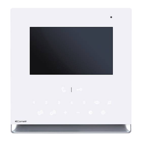
- Page 1 TECHNICAL MANUAL Technical manual for Icona SBC colour monitor Art. 6601W(/BM) Passion.Technology. Design.
-
Page 2: Table Of Contents
• All the equipment must only be used for the purpose it was designed for. Comelit Group S.p.A. declines any responsibility for improper use of the apparatus, for modifications made by third parties for any reason or purpose, and for the use of non-original accessories and materials. -
Page 3: Monitor Description
Monitor description 1. Microphone 2. 4.3’’ LCD screen 3. Soft-touch keys/Led 4. Loudspeaker 5. S1 User code programming microswitches (see table on page 17) 6. CV1 CV2 Jumper for separate power supply 7. CV5 Jumper for video closure 8. CV6 position A = contact IN1-IN2 >... -
Page 4: Soft-Touch Key Description
3 flashes (every 5 s.) = Doctor function enabled steady = privacy function enabled The monitor Art. 6601W is designed for use in colour systems, in the SB2 section downstream of Art. 4888C, or in systems without mixer, such as the system with 2-wire KIT or Art. 1210. -
Page 5: Installation
Installation Mounting the Icona SBC monitor on flush-mounted box Art. 6117 14,2 cm = 6 cm = 10 cm CLACK ! DISASSEMBLY... -
Page 6: Wall-Mounting (Art. 6620) / On 503 Series Box/Round Box
Wall-mounting (Art. 6620) / on 503 series box/round box with Art.6620* 14,2 cm with Art.6620* with Art.6620* L min = 6,5 cm L max = 7 cm * Art. 6620 (optional) CLACK ! DISASSEMBLY... -
Page 7: Installation On Plasterboard Walls With Mounting Kit Art. 6118
Installation on plasterboard walls with mounting kit Art. 6118 CLACK ! DISASSEMBLY... -
Page 8: Operation
Operation Answer incoming call Press the soft-touch audio activation key to answer incoming call. Activation/deactivation automatic answer mode f Press on the audio activation key for 5 sec » (ACTIVATION) + audio LED with FIXED ILLUMINATION » (DEACTIVATION) BEEP + audio LED OFF Monitor configuration Standard configuration for soft-touch keys DIP S2... -
Page 9: Advanced Monitor Configuration
Advanced monitor configuration Warning If the default settings (see table on page 8) do not reflect requirements, the keys can be programmed differently by carrying out the steps below. At the end, set S2 DIP switches 1-2-3-4 to the combination 1111 (PROG setting in the configuration tables on pages 9-15). -
Page 10: Programming Buttons For Intercom Call
Programming buttons for intercom call DIP S2 DIP S1 INTb INTb INTb ADDRESS INTb INTb INTb INTb PROG Example 1 - all systems (INCLUDING KITS!) - General intercom on a monitor with user code 5, P2 programming = general internal call, P3 = general intercom with address 9 Example 2 - Selective intercom on a monitor with user code 1 and intercom address 1, P2 programming = selective intercom with address 2, P3 = selective intercom with address 3... -
Page 11: Direct Programming Of Intercom Call
Direct programming of intercom call Allows direct programming of intercom call via the internal units. √ Requires 2 operators Step 1: enter programming mode Operator 1 and Operator 2 carry out the following procedures on 2 internal units: 1. Set S2 DIP switches 1-2 -3-4 to the combination 1111 2. -
Page 12: Programming Keys For Generic Or Coded Actuator
Programming keys for generic or coded actuator DIP S2 DIP S1 ADDRESS PROG Example: on a monitor with user code 5, P1 programming = generic actuator, = coded actuator (code 125) Take note of the DIP-switch settings 1. Set S2 DIP switches 6 to the combination 1. »... -
Page 13: Programming Buttons For Other Functions
Programming buttons for other functions DIP S2 DIP S1 ADDRESS NULL NULL NULL NULL NULL NULL NULL PROG Legend Lock- release Audio Self-ignition Main switchboard call – not for use in systems with KIT Secondary switchboard call – not for use in systems with KIT Guardian doorentry phone call Doctor Panic –... -
Page 14: Programming Range
Programming range Take note of the S2, S1 setting and restore it when programming is complete f Carry out steps 1 to 4 Range S2 DIP minimum 1 2 3 4 5 6 address 0 0 0 0 1 0 set code, TAB. -
Page 15: Led/Alarm/Lock-Release/Actuator Programming
LED/alarm/lock-release/actuator programming Take note of the S2, S1 setting and restore on completion of programming f Carry out steps 1 to 4 S2 DIP Input IN 1- IN 2 1 2 3 4 5 6 LED (default)* 0 0 0 1 1 0 Input CFP2 - IN 1 ALARM** Input CFP2 - IN 1... -
Page 16: Changing Monitor Ringtones
Changing monitor ringtones 1. Keep the button pressed until a confirmation tone is emitted (this operation is only possible with the system in stand- by; otherwise the signalling LED will flash to warn the user) 2. Press and release the button: once (1 confirmation tone is emitted) to change the ringtone of calls from the external unit. -
Page 17: Riser Addresses
Riser addresses TAB. A Dip switch Dip switch Dip switch Dip switch Dip switch Dip switch Dip switch Dip switch Code Code Code Code Code Code Code Code 1,2,3,4,5 1,3,4,5,6 1,2,4,5,7 1,4,5,6,7 1,2,3,5,8 1,3,5,6,8 1,2,5,7,8 2,3,4,5,6 3,4,5,7 2,4,5,6,7 4,5,8 2,3,5,6,8 3,5,7,8 1,2,3,4,5,6 1,3,4,5,7... -
Page 18: Operating Distances With Art. 4888C
6601W 1212/B 6601W/BM (MAX 1) A MAX B MAX F MAX H MAX D MAX Comelit Art. 4577/4579 1 mm2 (Ø 1,2 mm AWG 17) 200 m 200 m 50 m 100 m 100 m (655 feet) (655 feet) (165 feet) -
Page 19: Wiring Diagrams With Art. 4888C
Wiring diagrams with Art. 4888C System with 1 Ikall Series video port 4680C/4680KC 33436 Local door-opener button Art. 4680KC manages calls originating from ONLY digital or button modules if they fall between address 1 and address 10. SB2V/039ICIC... -
Page 20: Cascade Connection Of 2 Main Monitors Powered By Mixer Art. 4888C
SB2/A22IC Cascade connection of 2 main monitors and 1 secondary monitor with the same user code (in systems with Art. 4888C) SB2/A21IC Connection of main monitor with local power supply 1212/B 1216 6601W/ 6601W/ 6601W/ 1214/2C 6601W/BM 6601W/BM 6601W/BM 1234 67... -
Page 21: Operating Distances With Kit 8461I
1212/B 6601W/BM (MAX 1) 4893 A MAX B MAX D MAX Comelit Art. 4577/4579 1 mm2 (Ø 1,2 mm AWG 17) 200 m 100 m 100 m (655 feet) (330 feet) (328 feet) UTP5 cat. 5 0,2 mm2 (Ø 0,5 mm AWG 24) -
Page 22: Operating Distances With Art. 1210
4681 4681 A MAX B MAX C MAX H MAX D MAX Art. 1216 Comelit Art. 4577/4579 1 mm2 (Ø 1,2 mm AWG 17) 160 m 70 m 90 m 30 m 100 m (525 feet) (230 feet) (295 feet) -
Page 23: Wiring Diagrams With Kit 8461I And Art.1210
Wiring diagrams with KIT 8461I and Art.1210 KIT 8461I: standard single-family system 6601W/ 6601W/BM 1234 67 110-240V 30 Vdc 30 Vdc 1209 4893 Local door-opener button IK/039QC System with Art. 1210 1216 6601W/ 6601W/BM 1234 67 6601W/ 1214/2C 6601W/BM 1234 67... -
Page 24: Kit 8461I Or System With Art. 1210: Secondary Monitor In Branch Or Cascade Connection
KIT 8461I or system with Art. 1210: secondary monitor in branch or cascade connection 6601W/ 6601W/BM 1216 1234 67 1234 67 1214/2C 6601W/ 6601W/ 6601W/BM 6601W/BM 1234 67 1234 67 1234 67 1214/2C 1209/1210 SB2/A24ICA KIT 8461I or system with Art. 1210: secondary monitor in branch connection... -
Page 25: Kit 8461I Or System With Art. 1210: 2 Additional Secondary Monitors In Cascade Connection
KIT 8461I or system with Art. 1210: 2 additional secondary monitors in cascade connection 6601W/ 6601W/ 6601W/ 6601W/BM 6601W/BM 6601W/BM 1209 1210 SB2/A23IC Connection of main monitor with local power supply 1212/B 6601W/ 6601W/ 1216 6601W/BM 6601W/BM 1234 67 1234 67... -
Page 26: Connection Of Call Repetition Devices (Art. 1229 Or Art. 1122/A)
Connection of call repetition devices (Art. 1229 or Art. 1122/A) Connect only one call repetition device for each user code. If inductive loads are connected, the insertion of a 470nF capacitor in parallel with the C-NO contacts of Art. 1122/A is recommended SB2V/AAK Floor door call connection variant If there are a number of door-entry phones or monitor brackets with the... - Page 28 w w w . c o m e l i t g r o u p . c o m Via Don Arrigoni, 5 - 24020 Rovetta (BG) - Italy...