
Related Manuals for Comelit Icona


Summary of Contents for Comelit Icona
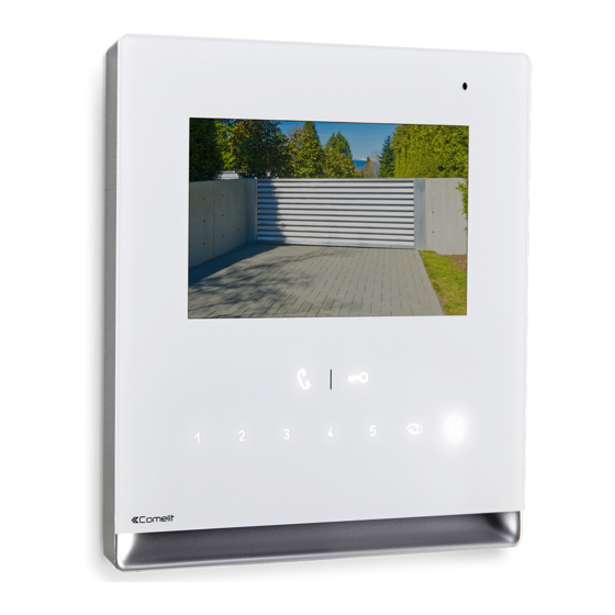
- Page 1 TECHNICAL MANUAL Icona 2-wire door entry monitor Art. 6601W - Art. 6601W/BM Passion.Technology.Design.
-
Page 2: Table Of Contents
• failure to observe the indications and warnings contained in this Manual / Instruction sheet. Comelit Group S.p.A. reserves the right to change the information provided in this Manual / Instruction Sheet at any time and without prior notice. Table of contents Description .................. -
Page 3: Description
Icona 6601W is a colour monitor equipped as standard with 9 function buttons and 6 adjustment buttons. Icona 6601W/BM is a colour monitor with 9 function buttons and 6 adjustment buttons, equipped with a magnetic amplification system for hearing aid devices. -
Page 4: Touch-Sensitive Button Activation
Touch-sensitive button activation f Swipe to enable the row (1) of function buttons. f Swipe again to enable the row (2) of adjustment buttons. f Press the desired button once to activate the function associated with it Wait for approximately 1 sec. before pressing the same button again. -
Page 5: Technical Specifications
Technical specifications GENERAL DATA 6601W 6601W/BM Product height (mm) Product width (mm) Product depth (mm) Product weight (g) Product colour White RAL9003, base grey RAL7001 White RAL9003, base grey RAL7001 Material ABS, Glass ABS, Glass Flush mounting Yes, with specific accessory Yes, with specific accessory Surface mounting Yes, with specific accessory... -
Page 6: Installation
Installation Installed in flush-mounted box art. 6117 14,2 cm = 6 cm = 10 cm CLACK ! DISASSEMBLY... -
Page 7: Art. 6620 Surface Mounting / In 503 Series Box / Round Box
Art. 6620 Surface mounting / in 503 series box / round box with Art.6620* 14,2 cm with Art.6620* with Art.6620* L min = 6,5 cm L max = 7 cm * Art. 6620 (optional) CLACK ! DISASSEMBLY... -
Page 8: Connections
Connections ADDITIONAL ALIMENTAZIONE SUONERIA ADDITIONAL POWER SUPPLY SUPPLEMENTARE SUPPLEMENTARE RINGTONE (SE NECESSARIA) (IF REQUIRED) 1229 1212/B FLOOR DOOR CHIAMATA FUORIPORTA CALL VIDEO ENTRY MONTANTE VIDEOCITOFONICA RISER 6601W 1214/2C PROGRAMMABLE INGRESSO INPUT PROGRAMMABILE MONTANTE VIDEO ENTRY VIDEOCITOFONICA RISER 20 m MAX - Connect a single call repetition device for each user code. 20 m MAX - Use shielded cable for the connection and do not route the cables in the vicinity of heavy inductive loads or power supply cables (230 V/400 V). -
Page 9: Settings
Settings Main and secondary door entry monitors In systems with power supply unit 1209, 1210 or 1210A, you can configure a maximum of 1 main door entry monitor (+3 powered separately), while in systems with power supply unit 4888C you can configure a maximum of 2 main door entry monitors (+1 powered separately). -
Page 10: Configuring Buttons
Configuring buttons By default the buttons control the functions in row A (“Basic configuration” table). It is possible to change the default configuration of the buttons by changing the positions of S2 DIP-switches 1-2-3-4 on the rear of the door entry monitor to one of the combinations (B-P) suggested in the table. All the buttons will change function. Basic configuration S2 DIP-switch DIP 1... -
Page 11: Advanced Configuration
Advanced configuration If the basic configuration settings (A-P) do not reflect requirements, the buttons can be programmed differently by carrying out the steps below. After programming, set S2 DIP-switches 1-2-3-4 (PROG) to ON. With these DIP-switch settings, the buttons manage the programmed functions. -
Page 12: Intercom Call To Selective Address: Button Programming
Intercom call to selective address: button programming 1. The steps illustrated in paragraph “Assigning a selective address” should be carried out on the devices involved in the intercom call. 2. Take note of the S1 DIP-switch settings. 3. To enter programming mode, set S2 DIP-switch 6 to ON. »... -
Page 13: Generic Actuator, Coded Actuator
Generic actuator, coded actuator Generic actuator: button programming 1. Take note of the S1 DIP-switch settings. 2. To enter programming mode, set S2 DIP-switch 6 to ON. » the LED flashes 3. Refer to the table “Basic configuration" to identify a DIP-switch combination in which the actuator function (ACT) corresponding to the button you want to program appears, then set the S2 DIP-switches. -
Page 14: Other Functions: Button Programming
Other functions: button programming 1. To enter programming mode, set S2 DIP-switch 6 to ON. » the LED flashes 2. Refer to the table “Basic configuration" to identify a DIP-switch combination in which the desired functions corresponding to the buttons you want to program appear, then set the S2 DIP-switches. Example: For button 4= Self Activation (AI) and button 5 = Call to Secondary Switchboard (CCS), set S2 DIP-switches 1-2- 3-4 as specified in row M in the "Basic configuration"... -
Page 15: Led/Alarm/Lock-Release/Actuator Programming
LED/alarm/lock-release/actuator programming Take note of the S2, S1 settings and restore on completion of programming Input IN 1- IN 2 LED (default)* Input CFP2 - IN 1 ALARM* OK prog: Input CFP2 - IN 1 LOCK-RELEASE* KO prog: Input CFP2 - IN 1 CODED set code, ACTUATOR*... -
Page 16: Programming Reset
Programming reset Factory settings: • Button functions for the S2 DIP-switches 1-2-3-4 combination • Intercom address absent • Range function and min./max. addresses absent • Ringtone reset • Input IN 1 - IN 2 > LED (default) • “Automatic answer”, “Automatic door opening on receipt of call” and “Silent” mode disabled Take note of the Set the DIP-switches as shown in the figure. -
Page 17: Addressing Table
Addressing table DIP-switch Code 1,2,3,4,5 1,3,4,5,6 1,2,4,5,7 1,4,5,6,7 1,2,3,5,8 1,3,5,6,8 1,2,5,7,8 2,3,4,5,6 3,4,5,7 2,4,5,6,7 4,5,8 2,3,5,6,8 3,5,7,8 1,2,3,4,5.6 1,3,4,5,7 1,2,4,5,6.7 1,4,5,8 1,2,3,5,6.8 1,3,5,7,8 2,3,4,5,7 3,4,5,6,7 2,4,5,8 4,5,6,8 2,3,5,7,8 1,2,6 1,2,3,4,5.7 1,3,4,5,6.7 1,2,4,5,8 1,4,5,6,8 1,2,3,5,7.8 2,3,4,5,6.7 3,4,5,8 2,4,5,6,8 4,5,7,8 1,2,3 1,3,6 1,2,7 1,6,7 127 1,2,3,4,5,6,7...