Panasonic TY-FB8TA Service Manual
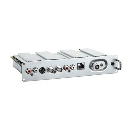
U/v tuner board with hospitality port
Hide thumbs
Also See for TY-FB8TA:
- Operating instructions manual (20 pages) ,
- Operating instructions manual (48 pages) ,
- Service manual (28 pages)
Table of Contents
Advertisement
Quick Links
Specifications
Receiving System
Receiving Channels
Regular TV
VHF BAND
2-12 (PAL/SECAM B, K1)
0-12 (PAL B AUST.)
1-9 (PAL B N.Z)
1-12 (PAL/SECAM D)
1-12 (NTSC M Japan)
2-13 (NTSC M U.S.A.)
OUTPUT
AUDIO OUT
AUDIO L-R (RCA Pin Type × 2)
VIDEO OUT
VIDEO (BNC Type)
Others
Ir System terminal × 1
INPUT
AUDIO IN
AUDIO L-R (RCA Pin Type × 2)
VIDEO IN
VIDEO (BNC Type)
S-VIDEO (MINI DIN 4-pin)
ANT-IN
UHF / VHF
Mass (Weight)
0.55 kg
U/V Tuner Board with Hospitality Port
TY-FB8TA
UHF BAND
21-69 (PAL G, H, I/SECAM G, K, K1)
28-69 (PAL B AUST.)
13-57 (PAL D, K)
13-62 (NTSC M Japan)
14-69 (NTSC M U.S.A.)
0.5 Vrms
1.0 Vp-p (75 W)
0.5 Vrms
1.0 Vp-p (75 W)
Y:1.0 Vp-p (75 W) C:0.286 Vp-p (75 W)
© 2004 Matsushita Electric Industrial Co., Ltd. All
rights
distribution is a violation of law.
ORDER NO. ITD0604015CE
CATV
S1-S20 (OSCAR)
1-125 (U.S.A. CATV)
C13-C49 (JAPAN)
S21-S41 (HYPER)
Z1-Z37 (CHINA)
5A, 9A (AUST.)
reserved.
Unauthorized
copying
and
Advertisement
Table of Contents

Related Manuals for Panasonic TY-FB8TA


Summary of Contents for Panasonic TY-FB8TA
-
Page 1: Specifications
ORDER NO. ITD0604015CE U/V Tuner Board with Hospitality Port TY-FB8TA Specifications Receiving System Receiving Channels Regular TV VHF BAND UHF BAND CATV 2-12 (PAL/SECAM B, K1) 21-69 (PAL G, H, I/SECAM G, K, K1) S1-S20 (OSCAR) 0-12 (PAL B AUST.) 28-69 (PAL B AUST.) -
Page 2: Table Of Contents
TY-FB8TA CONTENTS Page Page 1 Safety Precautions 8.2. HCA-Board Block Diagram 1.1. General Guidelines 8.3. HCA-Board (1 of 6) Schematic Diagram 1.2. Touch-Current Check 8.4. HCA-Board (2 of 6) Schematic Diagram 2 Prevention of Electro Static Discharge (ESD) to 8.5. HCA-Board (3 of 6) Schematic Diagram Electrostatically Sensitive (ES) Devices 8.6. -
Page 3: Safety Precautions
TY-FB8TA 1 Safety Precautions 1.1. General Guidelines 1. When servicing, observe the original lead dress. If a short circuit is found, replace all parts which have been overheated or damaged by the short circuit. 2. After servicing, see to it that all the protective devices such as insulation barriers, insulation papers shields are properly installed. -
Page 4: Prevention Of Electro Static Discharge (Esd) To Electrostatically Sensitive (Es) Devices
TY-FB8TA 2 Prevention of Electro Static Discharge (ESD) to Electrostatically Sensitive (ES) Devices Some semiconductor (solid state) devices can be damaged easily by static electricity. Such components commonly are called Electrostatically Sensitive (ES) Devices. Examples of typical ES devices are integrated circuits and some field-effect transistors and semiconductor "chip"... -
Page 5: About Lead Free Solder (Pbf)
TY-FB8TA 3 About lead free solder (PbF) Note: Lead is listed as (Pb) in the periodic table of elements. In the information below, Pb will refer to Lead solder, and PbF will refer to Lead Free Solder. The Lead Free Solder used in our manufacturing process and discussed below is (Sn+Ag+Cu). -
Page 6: Installation
TY-FB8TA 4 Installation... -
Page 7: Antenna Connection
TY-FB8TA 5 Antenna connection... -
Page 8: Connections Of External Equipment
TY-FB8TA 6 Connections of external equipment... -
Page 9: Circuit Board Layout
C486 JS310 R602 R507 JS311 C497 C585 TP3305 C539 SLOT 1 2 3 JK304 R604 L334 C709 R511 VIDEO IN MONITOR OUT C509 IC340 C533 C510 TP3306 Q329 TP305 R608 R742 TP3307 C713 C555 TY-FB8TA HCA-BOARD TXNHCA10YJT TY-FB8TA HCA-BOARD TXNHCA10YJT... - Page 10 R390 C379 C380 R321 C311 R694 R391 FL316 FL315 R688 R305 C308 R610 R689 R392 R690 R303 R331 C319 R316 C382 C318 R691 R313 R393 JK305 JK303 C383 Q301 JK304 JK300 R318 R322 R317 TY-FB8TA HCA-BOARD TXNHCA10YJT TY-FB8TA HCA-BOARD TXNHCA10YJT...
-
Page 11: Block And Schematic Diagram
TY-FB8TA 8 Block and Schematic Diagram 8.1. Schematic Diagram Notes... -
Page 12: Hca-Board Block Diagram
MAIN+3.3V IC3308 IC3312 IC3313 2.5V_AD VSOE TxIN25 MDIN0 MDOA0 MAIN+3.3V CLKE TxCLKIN AD 3.3V DDIF/OUT PLL 3.3V SDRAM PLL 1.8V MAIN_5V MAIN_5V MAIN_3.3V 3.3V MDIN15 LCD MUTE MDOA15 3.3V 1.8V LOUT ROUT TY-FB8TA HCA-Board Block Diagram TY-FB8TA HCA-Board Block Diagram... -
Page 13: Hca-Board (1 Of 6) Schematic Diagram
2SB0709A0L JS3304 J0JHC0000078 C3405 C3523 JS3301 0.1u R3336 JS3305 6.3V R3519 JS3302 R3331 4.7k 6.3V Q3328 JK3303 2SD0601A0L R3520 R3509 4.7k K2HC103B0105 Q3336 Ir System 2SD0601A0L TY-FB8TA HCA-Board (1 of 6) Schematic Diagram TY-FB8TA HCA-Board (1 of 6) Schematic Diagram... -
Page 14: Hca-Board (2 Of 6) Schematic Diagram
Vout L3328 J0JCC0000241 C3478 1000p C3490 C3458 C3460 C3468 C3466 0.01u MAIN3.3V 0.1u 0.1u 0.1u C3467 C3482 C3483 C3485 C3486 C3497 1000p 1000p R3492 1000p 0.1u TY-FB8TA HCA-Board (2 of 6) Schematic Diagram TY-FB8TA HCA-Board (2 of 6) Schematic Diagram... -
Page 15: Hca-Board (3 Of 6) Schematic Diagram
IC3300 IC3300 AD15 IC3300 IC3300 IC3300 IC3300 IC3300 IC3300 AD16 IC3300 IC3300 IC3300 IC3300 IC3300 IC3300 AE13 IC3300 IC3300 AE16 IC3300 IC3300 AF13 IC3300 IC3300 AF16 TY-FB8TA HCA-Board (3 of 6) Schematic Diagram TY-FB8TA HCA-Board (3 of 6) Schematic Diagram... -
Page 16: Hca-Board (4 Of 6) Schematic Diagram
SDA_PANEL GC3FM OSD A/D SDA0 IC3319 R3432 TVRN983 R3516 C3672 R3665 R3666 R3596 R3660 SCL_PANEL AI_SCL_2 SDA_PANEL R3597 AI_SDA_2 R3661 16k EEPROM R3517 HC-BOARD TXNHCA10YJT (4/6) TY-FB8TA HCA-Board (4 of 6) Schematic Diagram TY-FB8TA HCA-Board (4 of 6) Schematic Diagram... -
Page 17: Hca-Board (5 Of 6) Schematic Diagram
A1 A0 A13 A14 A15 C3684 0.1u AQ_D5 AO_A2 AO_A5 AQ_D9 0.1u AO_A3 AO_A4 R3728 EXB38V680JV C3732 0.1u IC3325 C0JBAB000591 INVERTER R3716 EXB38V680JV R3712 HC-BOARD TXNHCA10YJT (5/6) TY-FB8TA HCA-Board (5 of 6) Schematic Diagram TY-FB8TA HCA-Board (5 of 6) Schematic Diagram... -
Page 18: Hca-Board (6 Of 6) Schematic Diagram
R3760 0.01u 1000p MAIN1.8V VREF C3744 0.1u RUN/SS SYNC/MODE C3774 C3540 C3760 1000p 220u 0.1u L3356 G1C220MA0077 C3776 R3771 220p R3772 C3764 C3766 0.1u 71.5k 4.7u TY-FB8TA HCA-Board (6 of 6) Schematic Diagram TY-FB8TA HCA-Board (6 of 6) Schematic Diagram... -
Page 19: Replacement Parts List
TY-FB8TA 9 Replacement Parts List 9.1. Replacement Parts List Notes... -
Page 20: Electrical Replacement Parts List
TY-FB8TA 9.2. Electrical Replacement Parts List Ref. Part No. Part Name & Remarks Ref. Part No. Part Name & Remarks Description Description C3378- ECJ1XB1C104K C 0.1UF, Z, 16V C3300 ECJ1XF1C104Z C 0.1UF, Z, 16V C3385 ECJ1XF1C104Z C 0.1UF, Z, 16V... - Page 21 TY-FB8TA Ref. Part No. Part Name & Remarks Ref. Part No. Part Name & Remarks Description Description C3493- ECJ1XB0J105K C 1UF, K, 16V C3586 ECJ1XB1C104K C 0.1UF, Z, 16V C3587 ECJ1XB0J105K C 1UF, K, 16V C3497 ECJ1VF1A105Z C 1UF, Z, 10V...
- Page 22 TY-FB8TA Ref. Part No. Part Name & Remarks Ref. Part No. Part Name & Remarks Description Description C3690,9 ECJ1XF1C104Z C 0.1UF, Z, 16V D3308 MA157A DIODE D3309,1 MA152 DIODE C3692 ECJ1XB1C104K C 0.1UF, Z, 16V C3693 ECJ1XF1C104Z C 0.1UF, Z, 16V...
- Page 23 TY-FB8TA Ref. Part No. Part Name & Remarks Ref. Part No. Part Name & Remarks Description Description L3305,0 G1C330K00017 INDUCTOR COIL R3313 ERJ6GEYJ471 M 470 OHM,J,1/10W R3314,1 ERJ3GEYJ102 M 1KOHM,J,1/16W L3307 TALC168T6R8K CHIP INDUCTOR COIL L3310 TALC168T100K CHIP INDUCTOR COIL...
- Page 24 TY-FB8TA Ref. Part No. Part Name & Remarks Ref. Part No. Part Name & Remarks Description Description R3402 ERJ3GEYJ101 M 100 OHM,J,1/16W R3509 ERJ3GEYJ472 M 4.7KOHM,J,1/16W R3403 ERJ3GEY0R00 M 0 OHM, 1/16W R3511,1 ERJ3GEYJ220 M 22 OHM,J,1/16W R3404 ERJ3GEYJ101 M 100 OHM,J,1/16W...
- Page 25 TY-FB8TA Ref. Part No. Part Name & Remarks Ref. Part No. Part Name & Remarks Description Description R3612- ERJ3GEYJ680 M 68 OHM,J,1/16W R3732 ERJ3GEY0R00 M 0 OHM, 1/16W R3733,3 ERJ3GEYJ220 M 22 OHM,J,1/16W R3619- D1HG6808A002 NETWORK RESISTER R3735 EXB38V103J RESISTOR ARRAY...
-
Page 26: Mechanical Replacement Parts List
TY-FB8TA 9.3. Mechanical Replacement Parts List Ref. Part No. Part Name & Remarks Description N2QAYB000020 REMOTE CONTROL TBMU634 TUNER TERMINAL SHEET THEL0239 SCREW FOR INSTALLATION THEL027N SCREW FOR SHIELD PLATE TNQX016 IR SYSTEM CABLE K2ZZ02C00006 TPCB06810 CARTON BOX TPDF1137 PARTITION... -
Page 27: Parts Location
TY-FB8TA 9.4. Parts Location (1) - Page 28 TY-FB8TA 9.5. Parts Location (2)