Panasonic WJ-ND400 Installation Manual
Network disk recorder
Hide thumbs
Also See for WJ-ND400:
- Operating instructions manual (233 pages) ,
- Reference material (22 pages) ,
- Specifications (2 pages)
Table of Contents

Related Manuals for Panasonic WJ-ND400


Summary of Contents for Panasonic WJ-ND400
- Page 1 ND400_Basic.book 1 ページ 2008年4月8日 火曜日 午後3時59分 Network Disk Recorder Installation Guide WJ-ND400 Model No. Before attempting to connect or operate this product, please read these instructions carefully and save this manual for future use.
- Page 2 If you lose the fuse cover the plug must not be used until a replacement cover is obtained. A replacement fuse cover can be purchased from your local Panasonic Dealer. IF THE FITTED MOULDED PLUG IS UNSUITABLE FOR THE SOCK- ET OUTLET IN YOUR HOME THEN THE FUSE SHOULD BE REMOVED AND THE PLUG CUT OFF AND DISPOSED OF SAFELY.
- Page 3 ND400_Basic.book 3 ページ 2008年4月8日 火曜日 午後3時59分 The model number and serial number of this product may be found in the unit. You should note the model number and serial number of this unit in the space provided and retain this book as a permanent record of your purchase to aid identifi- cation in the event of theft.
- Page 4 ND400_Basic.book 4 ページ 2008年4月8日 火曜日 午後3時59分...
-
Page 5: Table Of Contents
ND400_Basic.book 5 ページ 2008年4月8日 火曜日 午後3時59分 Contents Preface Preface... 7 About these Operating Instructions... 7 System Requirements for a PC ... 8 Trademarks and Registered Trademarks ... 8 Network Security... 8 Precautions ... 9 Major Operating Controls and Their Functions ...11 Front View... 11 Inside the Front Cover ... - Page 6 Removing HDDs by unit... 50 Setting the HDD's Operation Mode... 51 HDD Error Recovery (During RAID Operation)... 52 Replacing Faulty HDD during RAID Operation ... 53 Rebooting... 54 Attachments Troubleshooting...55 Problems... 55 Specifications...57 WJ-ND400 ... 57 Accessories...58 Standard Accessories ... 58 Index...59...
-
Page 7: Preface
ND400_Basic.book 7 ページ 2008年4月8日 火曜日 午後3時59分 Preface The Network Disk Recorder (WJ-ND400) is for recording images and audio from network surveillance cameras to a hard disk (hereafter HDD). It is possible to connect up to 64 cameras over a network. Also, it is possible to access and operate the recorder via a network from the web browser on a computer (hereafter PC). A maximum of 16 PCs can be connected (via a network). -
Page 8: System Requirements For A Pc
ND400_Basic.book 8 ページ 2008年4月8日 火曜日 午後3時59分 System Requirements for a PC It is recommended to operate this unit using a PC that meets the following system requirements. ® • OS : Microsoft Windows Vista ® : Microsoft Windows ® : Microsoft Windows •... -
Page 9: Precautions
ND400_Basic.book 9 ページ 2008年4月8日 火曜日 午後3時59分 Precautions Refer all work related to the installation of this product to qualified service personnel or system installers. Do not operate the unit beyond their its specified temperature, humidity, or power source ratings. Use the unit at temperatures between +5 ºC - +45 ºC {41 ºF - 113 ºF} and where the humidity is between 5 % - 90 %. -
Page 10: Hard Disk Unit
LGPL. ⋅ For detailed information about the relevant software, refer to the "readme.txt" file in the "GPL/LGPL" folder on the CD- ROM included with the main unit. ⋅ Please note that Panasonic cannot respond to questions regarding the source code. -
Page 11: Major Operating Controls And Their Functions
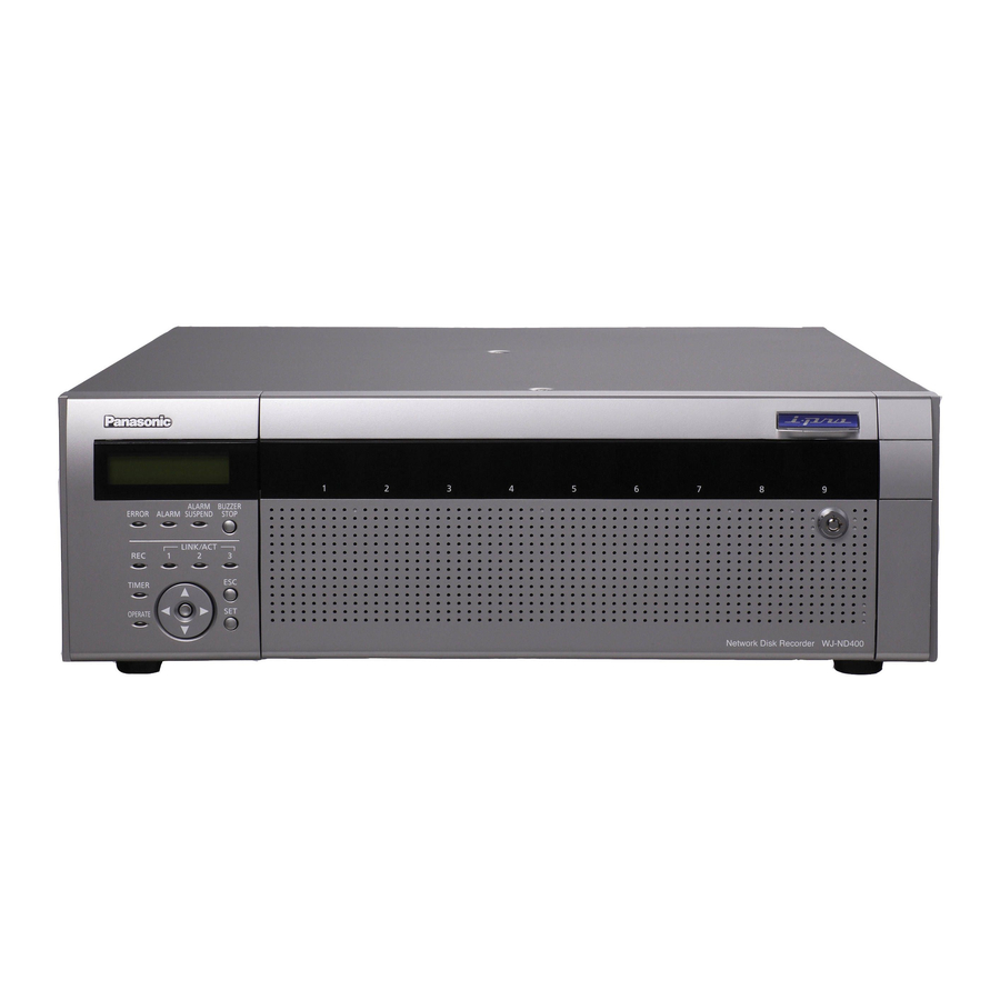
ND400_Basic.book 11 ページ 2008年4月8日 火曜日 午後3時59分 Major Operating Controls and Their Functions Front View (9) (10) (11) (12) (13) (1) Error indicator [ERROR] Blinks when errors or problems with the recorder's operation occur. Blinks red : System errors Blinks orange : Temperature is too high or low. Cooling fan stopped, etc. -
Page 12: Key
ND400_Basic.book 12 ページ 2008年4月8日 火曜日 午後3時59分 Major Operating Controls and Their Functions Important: • When the HDD indicators light red in the RAID5/RAID6 mode, quickly replace the HDD where the errors occurred. Contact your dealer for information on replacing HDDs. ⋅ RAID5 mode: Data cannot be recovered when two or more HDD indicators are lighting or blinking red. -
Page 13: Inside The Front Cover
ND400_Basic.book 13 ページ 2008年4月8日 火曜日 午後3時59分 Inside the Front Cover (6) (7) (1) USE button [USE] Used when adding or replacing an HDD or changing the operating mode of the HDD. Installing or : You can install or remove the HDD by removing an HDD holding down the button for at least 2 seconds, waiting for the buzzer to... - Page 14 ND400_Basic.book 14 ページ 2008年4月8日 火曜日 午後3時59分 Major Operating Controls and Their Functions (5) HDD bay slots Up to 9 HDD can be installed (one HDD unit is installed at the factory). Note: • Limiting factors for the RAID5/RAID6 mode. RAID5 mode : The RAID5 mode can be used when more than three HDDs are installed.
-
Page 15: Rear View
ND400_Basic.book 15 ページ 2008年4月8日 火曜日 午後3時59分 Rear View (1)(2) (3) (1) Handle for Maintenance Loosen the 5 screws indicated by the triangles and grip these handles to pull off the panel when replacing the fan or doing other maintenance work. (2) Alarm/Control connector [ALARM/ CONTROL], D-Sub 25 pin Use to connect alarm devices (buzzers or indicators), external devices, control switches controlled by the recorder. -
Page 16: Outline Of Functions
ND400_Basic.book 16 ページ 2008年4月8日 火曜日 午後3時59分 Outline of Functions Description of Functions Mega Pixel Camera Compatibility and Capacity The recorder can record high-definition images (mega pixel camera images) in SXGA (1280 x 960) JPEG four times that of the existing VGA (640 x 480). This makes it possible to record a wide angle of view and to zoom in without fuzziness to check things. -
Page 17: Hdd Fault Tolerance System
ND400_Basic.book 17 ページ 2008年4月8日 火曜日 午後3時59分 HDD Fault Tolerance System RAID 6 The RAID function makes it possible to improve the HDD's tolerance to errors. This product is equipped with the RAID6 mode that can recover image data when two HDDs fail, in addition to the RAID5 mode that can recover image data (RAID6 has two sets of error correcting code data). -
Page 18: Recording And Playing Images
• Command Alarm : Receives command alarms from PCs via a network. • Site Alarm : Receives the Panasonic alarm protocol from network cameras. Alarm operations are included in event operations. Recording of events is event recording, not alarm recording. -
Page 19: List Of Functions
FTP server. • A PC is notified of an alarm according to Panasonic alarm protocol settings. When an event or error occurs, a PC is automatically notified regarding event or error information according to the [Panasonic alarm protocol] settings. -
Page 20: Network
chap2.fm 20 ページ 2008年4月8日 火曜日 午後4時10分 Outline of Functions Network Remote Operation The recorder and cameras connected to it can be operated from a PC on the network. Enabled functions When monitoring images from a camera with pan and tilt function. Function Description Pan &... -
Page 21: Sd Memory Recording
ND400_Basic.book 21 ページ 2008年4月8日 火曜日 午後3時59分 SD Memory Recording If the connection with the camera is broken within the time set in the program in the recorder, images are recorded on the SD memory card in the camera. Recording Rate Setting SD memory recording can only be set when the camera supports it and the compression format is set to M-JPEG. -
Page 22: Getting Started
ND400_Basic.book 22 ページ 2008年4月8日 火曜日 午後3時59分 Getting Started Installation and Setup Setup Procedure The procedure to start operations is shown below. Rack Mounting Connections Power On Installing HDDs Recorder Network Settings PC Network Settings Initialize HDDs Camera Network Settings Setup Start Operations When necessary Replace HDDs Mount the recorder into the rack (page 23). -
Page 23: Setting Up The Rack
chap3.fm 23 ページ 2008年4月8日 火曜日 午後5時22分 Setting up the Rack Rack Mounting Install the recorder into an EIA standard compliant rack. EIA standard compliant : an EIA-standard 19"rack, depth product 550 mm or more (locally procured) Note: • Installation in a rack requires four M5 x 12 screws. Remove the 5 rubber feet from the underside of the recorder. -
Page 24: Rack Mounting Positions
ND400_Basic.book 24 ページ 2008年4月8日 火曜日 午後3時59分 Setting up the Rack Rack mounting positions When connecting multiple extension units (WJ-HDE400) to the recorder, place the recorder in the center of the rack. Connect the recorder and the extension unit with the connection cable (1 m {39.4 "}) included with the extension unit. Extension unit (unit number 5) Extension unit... -
Page 25: Connections
ND400_Basic.book 25 ページ 2008年4月8日 火曜日 午後3時59分 Connections This sections explains how to connect the PC, cameras, and extension units. The types of cables and other hardware depend on how each setup is done. Before starting installation work, check to make sure you have everything you need. Connecting the PC and the Camera Connect the PC and the camera to the recorder using a HUB. -
Page 26: Port Operation
ND400_Basic.book 26 ページ 2008年4月8日 火曜日 午後3時59分 Connections 2 Port Operation Using a HUB for Direct Connection The PC connects to the camera using the camera port and the client PC port on the rear of the recorder. Camera images input through the camera port are sent to the PC from the client PC port. Important: •... -
Page 27: Example Of Connectivity With 1 Port Operation
ND400_Basic.book 27 ページ 2008年4月8日 火曜日 午後3時59分 Example of Connectivity with 1 Port Operation Connecting to a PC over ADSL Network camera Note: • MPEG-4 video may not be displayed when using a router. Consult your network administrator about router settings. ADSL router (Commercially available) (Internet) ADSL line... - Page 28 ND400_Basic.book 28 ページ 2008年4月8日 火曜日 午後3時59分 Connections Connecting multiple units to the recorder LAN cable (Not provided: 10BASE-T / 100BASE-TX / 1 000BASE-T category 5e, straight (NTSC model) / category 7, straight (PAL model)) Recorder (1) Network camera LAN cable (Not provided: 10BASE-T / 100BASE-TX / 1 000BASE-T category 5e, straight (NTSC model) category 7, straight (PAL model))
-
Page 29: Example Of Connectivity With 2 Port Operation
ND400_Basic.book 29 ページ 2008年4月8日 火曜日 午後3時59分 Example of Connectivity with 2 Port Operation Connecting to a PC over ADSL Network camera ADSL router (Commercially available) Recorder LAN cable (Not provided: 10BASE-T / 100BASE-TX / 1 000BASE-T category 5e, straight (NTSC model) / category 7, straight (PAL model)) (Internet) ADSL line... - Page 30 ND400_Basic.book 30 ページ 2008年4月8日 火曜日 午後3時59分 Connections Connecting multiple units to the recorder Network camera Recorder (1) LAN cable (Not provided: 10BASE-T / 100BASE-TX / 1 000BASE-T category 5e, straight (NTSC model) / category 7, straight (PAL model)) Network camera LAN cable (Not provided: 10BASE-T / 100BASE-TX / 1 000BASE-T category 5e, straight (NTSC model) /...
-
Page 31: Connecting The Extension Unit
ND400_Basic.book 31 ページ 2008年4月8日 火曜日 午後3時59分 Connecting the Extension Unit You can connect a maximum of 5 extension units to a single recorder. Connect the recorder and the extension unit with the connection cable included with the extension unit. Connect as follows when connecting multiple extension units (WJ-HDE400) or adding a new connection. Also, be sure to read the user manual for the extension unit. -
Page 32: About Connectors
ND400_Basic.book 32 ページ 2008年4月8日 火曜日 午後3時59分 About Connectors Using the Alarm/Control connector You can use emergency recording and auto adjustment time functions when alarm equipment like a buzzer or indicator which is mounted externally. Create the connector by referring to the pin assignments. Pin Assignments The pin assignments are different for other Network Disk Recorders. -
Page 33: Connectivity For Emergency Recording
ND400_Basic.book 33 ページ 2008年4月8日 火曜日 午後3時59分 Name Number Alarm suspension input Outage detection input External recording mode switching input +5 V output Connectivity for Emergency Recording Turning [On] the external switch starts emergency recording. Emergency recording operations differ depending on the [Emergency rec.] settings accessed through the Setup menu (refer to Setup Instructions (PDF file)). -
Page 34: Auto Adjustment Time Function Connection 2
ND400_Basic.book 34 ページ 2008年4月8日 火曜日 午後3時59分 About Connectors Auto Adjustment Time Function Connection 2 When settings menu - [Basic] - [Time & date] - [Auto adjustment time] is set to [Slave] [Time Adjust Input] is available and the time on the recorder is synchronized with the other devices. 15 minutes before or after the set [Activation time] if a signal output from another device is input to the Adjustment Time I/O, the time on the recorder is set to the [Activation time]. -
Page 35: Uninterruptible Power Supply (Ups) Connectivity
ND400_Basic.book 35 ページ 2008年4月8日 火曜日 午後3時59分 Uninterruptible Power Supply (UPS) Connectivity This section explains how to connect an Uninterruptible Power Supply (hereafter UPS) as part of your power outage countermeasures. When the recorder receives a power outage detection signal from the UPS, it begins its internal power off sequence (process to stop recording to protect the recorder). -
Page 36: Using The Alarm Connector
ND400_Basic.book 36 ページ 2008年4月8日 火曜日 午後3時59分 About Connectors Using the Alarm Connector Used to connect alarm-related devices such as a sensor or a door switch. Create the connector by referring to the pin assignments. Pin Assignments The pin assignments are different for other Network Disk Recorders. Connect using the following chart. Name Number Alarm input 17... -
Page 37: Alarm Connectivity
ND400_Basic.book 37 ページ 2008年4月8日 火曜日 午後3時59分 Alarm Connectivity When a signal is input to Alarm Inputs 1 through 32 (Alarm connector pins 1 through 12 and 15 through 25, Alarm/Control connector pins 1 through 9), recording and camera images are shown according to the settings. When alarm devices such as a buzzer or indicator are installed externally, connect them to the Alarm output (Alarm/Control connector pin 21). -
Page 38: Alarm/Control Connector And Alarm Connector Timing And Polarity
ND400_Basic.book 38 ページ 2008年4月8日 火曜日 午後3時59分 About Connectors Alarm/Control connector and Alarm Connector Timing and Polarity Connectors Alarm input Alarm output Network error output Alarm reset input Emergency recording input Available disk space warning output HDD error output Camera error output Error output Time adjustment input/output Alarm suspension input External recording mode switching... -
Page 39: Power Supply
• The operate indicator lights and recorder/HDD check (system check) begins. • During system check, [WJ-ND400] appears on the LCD. Also, [Don't turn off] is displayed, followed by [System Checking]. • The Time display format screen appears when the system check is complete (page 40). -
Page 40: Using The Front Panel For Operations
ND400_Basic.book 40 ページ 2008年4月8日 火曜日 午後3時59分 Using the Front Panel for Operations Basic Operations Operate the recorder using the LCD and the buttons on the front panel. The LCD changes as follows when you press the arrow buttons (up or down). (Temperature will be displayed in Fahrenheit for NTSC model, e.g. -
Page 41: Checking System Information
ND400_Basic.book 41 ページ 2008年4月8日 火曜日 午後3時59分 Using the Front Panel for Operations Checking System Information For checking information (software version, hardware version, MAC address, or serial number) about the recording system. Check the settings by switching between screens using the following operations. The LCD changes as follows when using the arrow buttons (up or down). -
Page 42: Checking The Ip Address
ND400_Basic.book 42 ページ 2008年4月8日 火曜日 午後3時59分 Using the Front Panel for Operations Checking the IP Address You can check the DHCP, IP address, subnet mask, gateway #1, Client PC port (PC port): PT #2, and the Maintenance port: PT#3. Use the arrow buttons (left or right) to switch between ports. * Gateway and HTTP port settings are checked under the client PC port (PT #2). -
Page 43: Setting The Ip Address
ND400_Basic.book 43 ページ 2008年4月8日 火曜日 午後3時59分 Setting the IP Address Settable items are the same as those in "Checking the IP Address (page 42)". Configure the settings for each item by switching between screens using the following operations. When the cursor is ">", use the arrow buttons (up or down) to switch between screens. -
Page 44: Hdd Unit
chap3.fm 44 ページ 2008年4月8日 火曜日 午後5時21分 Using the Front Panel for Operations HDD Unit Use the HDD canister provided to install the HDD. The HDDs can be easily installed or removed from the HDD slots inside the front cover. Contact your dealer for information on purchasing, installing, and replacing HDDs. -
Page 45: Handling The Hdd
ND400_Basic.book 45 ページ 2008年4月8日 火曜日 午後3時59分 Handling the HDD Install the HDD unit provided (page 46). The HDDs can be easily installed or removed from the HDD bay slots inside the front cover. Contact your dealer for information on purchasing, installing, and replacing HDDs. Important: •... -
Page 46: Installing Hdds
ND400_Basic.book 46 ページ 2008年4月8日 火曜日 午後3時59分 Using the Front Panel for Operations Installing HDDs You can install HDDs from the recorder while it is in operation. Insert the key (included) into the key hole and turn it to the right while pressing gently to open the front cover. Insert the HDD units into the HDD bay slots while checking each HDD number marked on the HDD bay slots. -
Page 47: Installing Hdds By Unit
ND400_Basic.book 47 ページ 2008年4月8日 火曜日 午後3時59分 Select [YES] with the arrow buttons (left or right) and then press the [SET] button. The HDD is recognized for recording. Press the [SET] button to return to the display format screen. Close the front cover and lock it by lightly pressing and turning the key to the left. -
Page 48: Removing Hdds
ND400_Basic.book 48 ページ 2008年4月8日 火曜日 午後3時59分 Using the Front Panel for Operations Select [YES] with the arrow buttons (left or right) and then press the [SET] button. Select the number of the extension unit where you installed the HDD with the arrow buttons (up or down) and press the [SET] button. - Page 49 ND400_Basic.book 49 ページ 2008年4月8日 火曜日 午後3時59分 Select [YES] with the arrow buttons (left or right) and then press the [SET] button. The HDD stop process begins and the HDD status indicator blinks orange. The HDD status indicator goes out once the HDD stop process is complete.
-
Page 50: Removing Hdds By Unit
ND400_Basic.book 50 ページ 2008年4月8日 火曜日 午後3時59分 Using the Front Panel for Operations Removing HDDs by unit The HDDs in one extension unit can be removed simultaneously. For details refer to the operating instructions for the extension unit. Insert the key (included) into the key hole on the front cover of the extension unit and turn it while pressing in gently to open the front cover. -
Page 51: Setting The Hdd's Operation Mode
ND400_Basic.book 51 ページ 2008年4月8日 火曜日 午後3時59分 Check the disk information. Check the following content related to the HDD under [Disk information] on the settings menu. Refer to the Setup Instructions (PDF file) for more information. • HDD capacity • HDD remaining capacity •... -
Page 52: Hdd Error Recovery (During Raid Operation)
ND400_Basic.book 52 ページ 2008年4月8日 火曜日 午後3時59分 Using the Front Panel for Operations HDD Error Recovery (During RAID Operation) When errors occur during RAID5 or RAID6 operation, the HDD errors in the following table are displayed. When one HDD has errors ([1down]) in RAID5 mode, the data on the remaining HDDs can be read and recovery is possible. When two HDDs have errors ([2down]) in RAID6 mode, the data on the remaining HDDs can be read and recovery is possible. -
Page 53: Replacing Faulty Hdd During Raid Operation
ND400_Basic.book 53 ページ 2008年4月8日 火曜日 午後3時59分 Replacing Faulty HDD during RAID Operation When one HDD errors ([1down]) in RAID5 mode, the data on the remaining HDDs can be read and recovery is possible. When two HDDs errors ([2down]) in RAID6 mode, the data on the remaining HDDs can be read and recovery is possible. -
Page 54: Rebooting
ND400_Basic.book 54 ページ 2008年4月8日 火曜日 午後3時59分 Using the Front Panel for Operations Rebooting Press the [SET] button on the Manual Reboot screen to display the Manual Reboot ACCEPT screen. Select [YES] and press the [SET] button to reboot. [SET]... -
Page 55: Troubleshooting
ND400_Basic.book 55 ページ 2008年4月8日 火曜日 午後3時59分 Troubleshooting Attachments Problems Before requesting service, check the following items. Contact your dealer if the problem does not appear here, if the problem is not resolved by these remedies, or if you have any questions about settings and installation. Problem Power is not turn on. - Page 56 ND400_Basic.book 56 ページ 2008年4月8日 火曜日 午後3時59分 Troubleshooting Problem Cannot recover data after replacing HDDs (In RAID5/RAID6 mode) HDD indicator lights orange and red alternately even though recording or playback is not done. The power cord insulation is damaged. The power cord, AC inlet or the power plug are hot during use.
-
Page 57: Specifications
ND400_Basic.book 57 ページ 2008年4月8日 火曜日 午後3時59分 Specifications WJ-ND400 ● General Specifications Power source NTSC model: 120 V AC, 60 Hz PAL model: 220 V - 240 V AC, 50 Hz Power consumption 170 W Ambient operating +5 ºC to +45 ºC {41 °F - 113 °F}... -
Page 58: Accessories
ND400_Basic.book 58 ページ 2008年4月8日 火曜日 午後3時59分 Accessories Standard Accessories • CD-ROM ... 1 pc. • Installation Guide (this book) ... 1 pc. • Quick Reference Guide ... 1 pc. • Warranty (Only for NTSC model) ... 1 pc. * The CD-ROM contains the operating instructions (PDFs). The followings are for installation: •... -
Page 59: Index
ND400_Basic.book 59 ページ 2008年4月8日 火曜日 午後3時59分 Index 1 port operation ... 25 1 000BASE-T ... 25 100BASE-TX ... 25 10BASE-T ... 25 2 port operation ... 26 Accessing Live Images... 18 Active time... 38 ADSL ... 27, 29 Alarm connectivity ... 37 Alarm input ... - Page 60 This symbol might be used in combination with a chemical symbol. In this case it complies with the requirement set by the Directive for the chemical involved. For U.S., Canadian and Puerto Rican fields: Panasonic System Solutions Company, Unit Company of Panasonic Corporation of North America www.panasonic.com/business/ For customer support, call 1.800.528.6747 Three Panasonic Way 2H-2, Secaucus, New Jersey 07094 Panasonic Canada Inc.