Panasonic TU-PTA500U Operating Instructions Manual
Controller / tuner
Hide thumbs
Also See for TU-PTA500U:
- User manual (64 pages) ,
- Operating instructions manual (64 pages)
Table of Contents
Advertisement
Quick Links
Download this manual
See also:
User Manual
POWER
R-STAND BY
G-POWER ON
MENU
ACTION INPUT
VOLUME
Before connecting, operating or adjusting this product, please read these instructions completely. Save this manual for
future reference.
INPUT 3
S-VIDEO
VIDEO
L-AUDIO-R
CHANNEL
For assistance, please call : 1-888-VIEW-PTV (843-9788)
or send e-mail to : consumerproducts@panasonic.com
or visit us at www.panasonic.co.jp/global/
For assistance, please call : 787-750-4300
For assistance, please call : 1-800-561-5505
or visit us at www.panasonic.co.jp/global/
CONTROLLER / TUNER
Operating Instructions
Model No.
TU-PTA500U
(U.S.A)
(Puerto Rico)
(Canada)
TQBC0216
®
Advertisement
Table of Contents

Related Manuals for Panasonic TU-PTA500U


Summary of Contents for Panasonic TU-PTA500U
-
Page 1: Operating Instructions
ACTION INPUT VOLUME CHANNEL TU-PTA500U Model No. For assistance, please call : 1-888-VIEW-PTV (843-9788) or send e-mail to : consumerproducts@panasonic.com or visit us at www.panasonic.co.jp/global/ (U.S.A) For assistance, please call : 787-750-4300 (Puerto Rico) For assistance, please call : 1-800-561-5505 or visit us at www.panasonic.co.jp/global/... -
Page 2: Important Safety Instructions
WARNING RISK OF ELECTRIC SHOCK DO NOT OPEN WARNING: To reduce the risk of electric shock do not remove cover or back. No user-serviceable parts inside. Refer servicing to qualified service personnel. The lightning flash with The exclamation point within arrow-head within a triangle a triangle is intended to tell is intended to tell the user... - Page 3 Important Safety Instructions EXAMPLE OF ANTENNA GROUNDING AS Power-Cord Protection PER (NEC) NATIONAL ELECTRICAL CODE Power-supply cords shall be routed so that they are not likely to be walked on or pinched by items placed upon or against them, paying ANTENNA particular attention to cords at plugs, LEAD-IN WIRE...
-
Page 4: Fcc Statement
Responsible Party: TU-PTA500U Matsushita Electric Corporation of America One Panasonic Way Secaucus. NJ 07094 1-800-528-8601 This device complies with Part 15 of the FCC Rules. Operation is subject to the following two conditions: (1) This device may not cause harmful interference, and (2) this device must accept any interference received, including interference that may cause undesired operation. -
Page 5: Table Of Contents
Dear Panasonic Customer Welcome to the Panasonic family of customers. We hope that you will have many years of enjoyment from your new Controller / Tuner set. To obtain maximum benefit from your set, please read these Instructions before making any adjustments, and retain them for future reference. -
Page 6: Installation
Installation ACCESSORIES Check the accessories before installations. • • • • • Operating Remote Control Battery for the Remote Display Cable Warranty Card Instruction book Transmitter Control Transmitter K1HA26FA0001 TQBC0216 EUR511164 (2 AA (IEC R6) size) LIGHT POWER ASPECT MUTE TV/VIDEO ACTION MENU... -
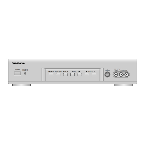
Page 7: Controls And Terminals On The Controller / Tuner
Installation Controls and terminals on the CONTROLLER / TUNER CONTROLLER/TUNER TU-PTA500U INPUT 3 R-STAND BY POWER S-VIDEO VIDEO L-AUDIO-R G-POWER ON MENU ACTION INPUT VOLUME CHANNEL POWER Menu button Input 3 terminals Indicator (see page 18) Video camera cable (see page 15) -
Page 8: Connecting The Antenna Cable To The Rf In Terminal
Installation Connecting the antenna cable to the RF In Terminal Antenna Connection - For proper reception of VHF / UHF channels, an external antenna is required. For best reception an outdoor antenna is recommended. Antenna Mode must be set to this unit. VHF Antenna UHF Antenna Mixer... - Page 9 Installation Antenna Connection (Cable Box, no VCR) Use this configuration when connecting this unit to a cable TV system using a Cable Box. CABLE BOX AUDIO OUT TERMINAL COMPONENT OUTPUT VIDEO INPUT ON BACK OF PC-IN CABLE BOX INPUT DISPLAY OUT AUDIO Y VIDEO AUDIO...
-
Page 10: How To Connect This Unit And Wide Plasma Display
Installation How to connect this unit and Wide Plasma Display AUDIO OUT COMPONENT OUTPUT VIDEO INPUT PC-IN INPUT DISPLAY OUT AUDIO VIDEO AUDIO VIDEO S-VIDEO Display cable (Supplied) AUDIO AUDIO VIDEO AUDIO S-VIDEO COMPONENT/RGB IN PC IN TUNER IN SERIAL —... -
Page 11: How To Connect The Output Terminals
Installation How to connect the OUTPUT Terminals Connect to the S-VIDEO or Video terminals. S-Video S-VIDEO cable Video VIDEO Audio AUDIO Video Monitor OUTPUT INPUT — R - STANDBY G POWER ON OUTPUT Note: INPUT The video signal input to the COMPONENT input and PC input will not be output from the output terminal. -
Page 12: How To Connect The "1, 2" Input Terminals
Installation How to connect the “1, 2” Input Terminals Connects VCRs and other peripheral equipment (INPUT 1, 2) (Example) When connecting a S-VIDEO VCR S-VIDEO cable S-VIDEO VCR S-Video Video audio cable Audio INPUT OUTPUT INPUT AUDIO VIDEO S-VIDEO (Example) When connecting the Composite Video connector. VIDEO cable VIDEO VCR Video... -
Page 13: How To Connect
Installation How to connect the Input 3 Terminals INPUT 3 POWER R-STAND BY S-VIDEO VIDEO L-AUDIO-R G-POWER ON MENU ACTION INPUT VOLUME CHANNEL INPUT 3 S-VIDEO VIDEO L-AUDIO-R A video camera uses the Connect the S-VIDEO or Video Input 3 terminal on VIDEO terminal. -
Page 14: How To Connect The Pc Input Terminals
Installation How to connect the PC Input Terminals Computer INPUT 3 POWER R-STAND BY S-VIDEO VIDEO L-AUDIO-R G-POWER ON MENU ACTION INPUT VOLUME CHANNEL PC-IN Conversion adapter (if necessary) D-sub 15p PC cable 1/8” (3 mm) stereo plug Connect a cable which matches the audio output terminal on the computer. -
Page 15: Power On / Off And Input Signal Selection
Power ON / OFF and Input Signal Selection Power ON / OFF Connect the plug to the Wall Outlet Push the POWER switch on this unit to turn the set on POWER-ON INPUT 3 R-STAND BY POWER S-VIDEO VIDEO L-AUDIO-R G-POWER ON MENU ACTION INPUT... -
Page 16: Location Of Controls
Location of Controls Illuminated Remote Control Power button Press to turn this unit ON or OFF. (See page 15) Note: The CONTROLLER / TUNER’s power cord must first be plugged into the wall outlet and then turned on at the POWER switch. MUTE button Push this button to mute the sound. - Page 17 Location of Controls ASPECT button Change of screen size (See page 22). Panasonic AUTO NORMAL JUST Turning ON and OFF the remote control illumination FULL ZOOM Remote control R-TUNE illumination can be turned Lights the remote control buttons ON and OFF by pressing The selected button blinks when lit.
-
Page 18: Flow Chart Of Main Menu
Flow Chart of Main menu If the MENU button is pressed, the Select MENU desired by MENU screen will be displayed. pushing Right “ ” button or If the MENU button is pressed once more Left “ ” button. while the menu screen is displayed, the The Right “... - Page 19 EXIT ID - 1 see page 51 CHANGE SELECT CHANGE SETTING see page 38, 39 PAGE 3/3 EXIT Panasonic AUTO 4 : 3 VIDEO INPUT LABEL see page 20, 21 ENTER CODE FIRST JUST NORMAL 480p COLOR MATRIX SDTV HDTV...
-
Page 20: Tuning Channels (Automatic Channel Programming)
Tuning channels (Automatic channel programming) Automatically searches and adds receivable channels in the installed area and / or CATV signals to the program. Channel tuning cannot be performed when the MAIN picture is not receiving a TV broadcast (tuning is not possible). MENU Press the MENU button to display the MENU screen and select SETUP. -
Page 21: Tuning Channels (Manual Channel Programming)
Tuning channels (Manual channel programming) Use this setting when changing setting of receiving channels or changing the channel display. Turn this unit on and select the broadcast channel. Follow the steps on the previous page to display the PROGRAM CHANNEL screen. This PROGRAM CHANNEL screen can be displayed when the MAIN picture is a TV broadcast. -
Page 22: Aspect Controls
When the ASPECT button is pressed, the screen mode switches to VCR/DBS CHANNEL PAUSE TV/VCR Panasonic AUTO, regardless of the mode the screen is set to. OPEN/CLOSE SLOW STILL Notes: (1) For a 480p signal input during component input signal mode, the mode switches ZOOM and FULL only. - Page 23 Notes: For an elongated image Image is expanded (1) Panasonic AUTO mode is designed to automatically adjust the aspect ratio to handle a mix of 16:9 and Panasonic Changes in accordance 4:3 program material. Certain 4:3 program material,...
-
Page 24: Vhf, Uhf And Catv
VHF, UHF and CATV INPUT 3 R-STAND BY POWER S-VIDEO VIDEO L-AUDIO-R G-POWER ON MENU ACTION INPUT VOLUME CHANNEL Operation can be done from this unit. • Channel buttons • Volume buttons Power switch Press to turn this unit on (See page 15). POWER LIGHT POWER... -
Page 25: Cable Tv
MENU INFO/RECALL SURROUND NORMAL OFF TIMER Note: The remote control code number is set for EXIT VCR REC GUIDE Panasonic products. PLAY STOP When peripheral equipment do not operate, reset code (See page 54). TV/VCR VCR/DBS CHANNEL PAUSE OPEN/CLOSE SLOW STILL Operate the cable TV tuner and select the desired volume level. -
Page 26: Selection Input Signal
Selection input signal Confirming connection of the connector for desire selection signal. COMPONENT 1 COMPONENT 2 AUDIO OUT COMPONENT OUTPUT VIDEO INPUT PC-IN Laser Disk Player INPUT DISPLAY OUT AUDIO VIDEO AUDIO VIDEO S-VIDEO DVD Player VIDEO 1 This equipment can VIDEO 2 also be connected to VIDEO 3... -
Page 27: Recall
Recall Recall (On-screen display) TV, VIDEO input mode The channel number remains, but other information INFO/RECALL LIGHT POWER disappears after 10 seconds. Press this button again to ASPECT MUTE TV/VIDEO delete channel number display. Full Information Channel number channel number or Video CH123 CH123 Input Selected... -
Page 28: Adjusting Screen Position/Size(Tv,Video Input Mode)
Adjusting screen POSITION/SIZE (TV, VIDEO input mode) Adjusting screen ASPECT Press to select the screen mode to adjust. LIGHT POWER ASPECT MENU MUTE TV/VIDEO Press to display the MENU. Press to select MENU ADJUST menu. ADJUST SET UP ACTION PICTURE ACTION PICTURE ADJUST MENU... - Page 29 Adjusting screen POSITION/SIZE (TV, VIDEO input mode) Switching screen width During NORMAL mode, if noise appears on the ends of the image in SIZE 1, switch to SIZE 2. Press to widen (SIZE 2). (SIZE 1) (SIZE 2) ACTION Press to narrow (SIZE 1). During JUST mode, if noise appears on the ends of the image in SIZE 1, switch to SIZE 2.
-
Page 30: Adjusting Picture Pos./Size (Pc Input Mode)
Adjusting PICTURE POS./SIZE (PC input mode) MENU Press to display PC MENU screen. LIGHT POWER ASPECT PC MENU MUTE TV/VIDEO PICTURE Press to select the PICTURE POS. / SIZE PICTURE POS./ SOUND ACTION SIZE. SIGNAL SELECT ACTION EXIT Press to display PICTURE POS./SIZE MENU INFO/RECALL... - Page 31 Adjusting PICTURE POS./SIZE (PC input mode) When the Position Left “ ” button is pressed When the Position Right “ ” button is pressed H-POS When the Position Left “ ” button is pressed When the Position Right “ ” button is pressed H-SIZE When the Position Left “...
-
Page 32: Sound Adjustments (Tv,Video Input Mode)
Sound Adjustments (TV, VIDEO input mode) MENU Press the MENU button to display the MENU screen and select ADJUST. ADJUST SET UP PICTURE PICTURE ADJUST Select SOUND ADJUST of ADJUST from the MENU screen. POSITION / SIZE AUDIO SOUND ADJUST Press to select SOUND ADJUST AUDIO MODE ACTION... -
Page 33: Audio Adjustments (Pc Input Mode)
Sound Adjustments (PC input mode) PC MENU Press the MENU button to display the PC MENU screen. PICTURE PICTURE POS. / SIZE SOUND SIGNAL Press to select SOUND. SELECT ACTION EXIT SOUND NORMALIZE Press to display SOUND menu screen, NORMAL AUDIO MENU STANDARD BASS... -
Page 34: (For Tv, Video Input Mode)
Picture Adjustments (for TV, VIDEO input mode) MENU Press the MENU button to display the MENU screen and select ADJUST. ADJUST SET UP PICTURE PICTURE ADJUST Press to select PICTURE ADJUST. POSITION / SIZE AUDIO ACTION SOUND ADJUST AUDIO MODE Press to display the PICTURE ADJUST screen. - Page 35 Picture Adjustments (for TV, VIDEO input mode) PICTURE Selects proper brightness and density for the PICTURE ADJ. room. NORMALIZE PICTURE MENU STANDARD BRIGHTNESS Adjusts for easier viewing of dark pictures PICTURE such as night scenes and hair. BRIGHTNESS COLOR COLOR Adjusts slightly to a lighter color.
-
Page 36: Picture Adjustments (Pc Input Mode)
Picture Adjustments (PC input mode) PC MENU Press the MENU button to display the MENU screen and select ADJUST. PICTURE PICTURE POS. / SIZE SOUND Press to select to PICTURE. SIGNAL ACTION SELECT EXIT Press to display the PICTURE screen. PICTURE NORMALIZE NORMAL... -
Page 37: Surround Controls
SURROUND Controls SURROUND Button SURROUND The benefits of surround sound are enormous. You can be completely enveloped in sound, just as if you were at LIGHT POWER a concert hall or cinema. ASPECT MUTE TV/VIDEO The surround setting switches on and off each time the SURROUND button is pressed. -
Page 38: Closed Captions
Closed Captions This unit has a built in decoder that provides a visual depiction of the audio portion of a television program in the form of written words across the screen (white or colored letters on a black background). It allows the viewer to read the dialogue of a television program or other information. - Page 39 Closed Captions CLOSED CAPTION CC MODE ON MUTE Activates the On-Screen Closed Caption feature. When activated this feature MODE will remain on until OFF is selected in this menu. CHANGE SELECT Press to select CC MODE. EXIT Press to select from the following: ACTION •...
-
Page 40: Lock Feature
Lock Feature In the United States, the V-CHIP consists of two rating systems, which are MPAA (MOTION PICTURE) and TV PARENTAL GUIDELINES. Its function is to block programs by the rating data in the XDS data packets sent from broadcasting stations. The user can select which rating programs should be blocked by the LOCK MENU options. - Page 41 Lock Feature MOTION PICTURE RATING VIEW NR PROGRAMS? Press to select rating to lock. ACTION PG–13 Press to select YES or NO. NC–17 Rating (turns red when on) CHANGE SELECT : General audience ACTION EXIT : Parental guidance suggested PG-13: Parental guidance needed under 13 years old : Restricted NC17 : No one under 17 is admitted : Pornography...
- Page 42 Lock Feature TV PARENTAL STATUS LOCK MOTION PICT. STATUS Press to select TV PARENTAL STATUS. CHANGE SETTING Press to select ON or OFF. TV PARENTAL STATUS ACTION CHANGE SETTING CHANGE CODE CHANGE SELECT Changing setting EXIT TV PARENTAL GUIDE Press to select CHANGING SETTING VIEW NR PROGRAMS? (the menu following TV PARENTAL STATUS).
-
Page 43: Customizing The Video Input Labels
Customizing the VIDEO INPUT labels Display for each VIDEO INPUT can be changed to match with the connected device (VCR, DVD Player). Example: When changing VIDEO 3 to LD. MENU Press the MENU button to display the MENU screen and select SETUP. ADJUST SET UP (Except in PC input mode) - Page 44 Customizing the VIDEO INPUT labels VIDEO INPUT LABEL VIDEO1 VIDEO1 Press to select VIDEO INPUT to change. VIDEO2 VIDEO2 VIDEO3 VIDEO3 ACTION COMPONENT1 COMPONENT1 COMPONENT2 COMPONENT2 CHANGE SELECT EXIT Press to change. ACTION By pressing this button, display changes as follows: TION VIDEO 2 BLANK...
-
Page 45: Selecting Stereo / Sap / Mono
Selecting STEREO / SAP / MONO Press the MENU button to display the MENU screen and select ADJUST. MENU (Except in PC input mode) ADJUST SET UP PICTURE PICTURE ADJUST Press to select AUDIO MODE. POSITION / SIZE AUDIO ACTION SOUND ADJUST AUDIO MODE Press to display the AUDIO MODE screen. -
Page 46: Optimizing Display For Dvc Recording Mode
Optimizing display for DVC recording mode (DVC PLAYBACK MODE) When digital video camera recording is in FRAME, images will have high resolution. MENU Press the MENU button to display the MENU screen and select SETUP. ADJUST SET UP (Except in PC input mode) LANGUAGE PROGRAM CHANNELS Press to select VIDEO. -
Page 47: Adjusting Unnatural Video Images (3D Y/C Filter)
EXIT Switching to 3D Y/C FILTER VIDEO PAGE 2/3 Press to select 3D Y/C FILTER. 3D Y / C FILTER ACTION ID - 1 Panasonic AUTO 4 : 3 JUST NORMAL Press to turn OFF. CHANGE SELECT EXIT ACTION MENU Press to end. -
Page 48: Automatically Changing Screen Size For Video Input Modes
: When screen size specification signals are detected, screen size is ACTION ID - 1 automatically changed. Panasonic AUTO 4 : 3 OFF : The screen size is not automatically JUST NORMAL changed. (Turn OFF if this function does not operate properly.) -
Page 49: Cancelling Automatic Enlarging Of Screen
Cancelling automatic enlarging of screen Used for viewing 4:3 images in Panasonic auto mode. (See page 23) MENU Press the MENU button to display the MENU screen and select SETUP. ADJUST SET UP (Except in PC input mode) LANGUAGE PROGRAM CHANNELS Press to select VIDEO. -
Page 50: Setting When 480P Signals (Sequential Scan) Are Input Through Component Video Input
Setting when 480p signals (sequential scan) are input through COMPONENT VIDEO INPUT Displays input signals (480p signals) in a natural color from digital equipment adapters connected to COMPONENT VIDEO INPUT (Y, P input terminals). MENU Press the MENU button to display the MENU screen and select SETUP. ADJUST SET UP (Except in PC input mode) -
Page 51: Switching Languages For Display
Switching languages for display MENU Press the MENU button to display the MENU screen and select SETUP. ADJUST SET UP (Except in PC input mode) LANGUAGE PROGRAM CHANNELS Press to select LANGUAGE. LOCK ACTION CLOSED CAPTION VIDEO Press to display the LANGUAGE screen. PAGE ACTION SELECT... -
Page 52: Set Up For Pc Input Signals
SET UP for PC Input Signals Press the MENU button to display the PC MENU screen, and select PC SIGNAL MENU. SYNC H & V Press to select each item. PULL-IN RANGE NARROW CLAMP POSITION H-FREQ. 31.5 Press to adjust. V-FREQ. -
Page 53: Operating Peripheral Equipment Using The Remote Control
If an incorrect number is entered (or there is an incomplete entry after 28 seconds), the key illumination goes out (no blink) and setting are unchanged. Device Operate Default TV (Only Panasonic) Panasonic Code VCR (Preset) Panasonic Code Cable Boxes (Preset) - Page 54 Operating peripheral equipment using the remote control 2. Setting to the remote using the step and set method (When code not known): Press and hold the POWER and ACTION POWER keys simultaneously for three full seconds. After 3 seconds, all the illuminated mode LIGHT keys will begin to flash.
- Page 55 16 and 58 to 60 for details on operating peripheral equipment using the remote control. VCR Infrared Codes Index Maker List (VCR) Maker Set Up No. Maker Set Up No. ADMIRAL PANASONIC 125, 130, 100, 101 AIWA 137, 160 PENNEY 130, 000, 300, 005, 240, AKAI 142, 014, 015, 016...
- Page 56 003, 004, 005 TOSHIBA MEMOREX UNIKA 544, 531 MOVIETIME 544, 005 UNIVERSAL 522, 544 710, 702, 002 VIDEOWAY PANASONIC 120, 121, 132 VIEWSTAR 541, 542 PHILIPS 541, 542, 006 ZENITH 280, 000 PIONEER 001, 260 ZENITH / DRAKE SATELLITE Maker List (DVD)
- Page 57 Operating peripheral equipment using the remote control CASSETTE PLAYERS, RECEIVERS, AMPLIFIERS, and DBS Infrared Codes Index Maker List (TAPE) Cassette Players Maker Set Up No. Maker Set Up No. PANASONIC 700, 730 TECHNICS 700, 730 Maker List (RCVR) Receiver Amplifiers Maker Set Up No.
- Page 58 Operating peripheral equipment using the remote control Remote Control: Quick Reference Functional Key Control MODE FUNCTION TV, DTV, VCR Select Channel AUX (VCR2) CABLE, DBS RCVR 1 Selects Video 1 (Receiver / Amplifier) 2 Selects Video 2 3 Selects Video 3 4 Selects Video 4 5 Selects CD 6 Selects Tuner...
- Page 59 Operating peripheral equipment using the remote control Remote Control: Quick Reference Functional Key Control MODE FUNCTION TV, VCR TV Volume Up / Down CABLE Cable Volume Up / Down Audio Track + / –, Navigation Right / Left ACTION DVD (DVD) Navigation Right / Left DVD (CD) RCVR Volume Up / Down...
- Page 60 Operating peripheral equipment using the remote control Remote Control: Quick Reference Functional Key Control MODE FUNCTION VCR Pause PAUSE DVD (DVD, LD) Still STILL DVD (CD) Pause AUX ( Tape Cassette Player ) Tape Pause TV/VCR Switch TV/VCR DVD (DVD, CD, LD) Open / Close OPEN/CLOSE Tape Open / Close...
-
Page 61: Troubleshooting
The image distorts when channels are changed. – moment when changing channels using the VCR. • During Panasonic AUTO Depending on the program content, even when the screen is mode, the screen size supposed to automatically zoom, if the beginning scene is dark, it 23, 49 sometimes changes. -
Page 63: Specifications
Specifications Power Source AC 120 V, 50 / 60 Hz Power Consumption Average 35 W Stand-by Power-OFF 3.5 W OUTPUT DISPLAY OUT D-SUB 26-pin OUTPUT VIDEO (Pin Jack Type) 1.0 Vp-p (75 ) S-VIDEO (Mini DIN 4-pin) Y: 1 Vp-p (75 ) C: 0.286 Vp-p (75 ) AUDIO L-R (Pin Jack Type 0.5 Vrms... - Page 64 Division of Matsushita Electric 5770 Ambler Drive Electric Corporation of America of Puerto Rico Inc. (“PSC”) Mississauga, Ontario One Panasonic Way Secaucus Ave. 65 de Infanteria, Km 9.5 L4W 2T3 New Jersey 07094 San Gabriel Industrial Park, Carolina, Puerto Rico 00985...