Yamaha CL5 Owner's Manual
Hide thumbs
Also See for CL5:
- Reference manual (306 pages) ,
- Supplementary manual (26 pages) ,
- Quick start manual (6 pages)
Table of Contents
Advertisement
Quick Links
Advertisement
Table of Contents

Related Manuals for Yamaha CL5


Summary of Contents for Yamaha CL5
- Page 1 Owner’s Manual Keep This Manual For Future Reference.
-
Page 2: Table Of Contents
Contents Setup..........35 Specifying the brightness of the touch screen, LEDs, channel name displays, and lamps...35 Setting the date and time of the internal PRECAUTIONS........5 clock ............35 Word clock connections and settings ....36 Introduction ........7 Making HA (Head Amp) analog gain settings ...37 Sending an input channel signal to the Welcome! ............7 STEREO bus..........38... - Page 3 The above warning is located on the rear of the unit. L’avertissement ci-dessus est situé sur l’arrière de l’unité. Explanation of Graphical Symbols Explication des symboles The lightning flash with arrowhead symbol within an equilateral triangle is intended to alert the user to the presence of uninsulated “danger- ous voltage”...
- Page 4 Yamaha Corporation of America or its subsidiaries. of other electronic devices. Compliance with FCC regulations does * This applies only to products distributed by YAMAHA CORPORATION OF AMERICA. (class B) ADVARSEL! COMPLIANCE INFORMATION STATEMENT Lithiumbatteri—Eksplosionsfare ved fejlagtig håndtering.
-
Page 5: Precautions
• Do not block the vents. This device has ventilation holes at the rear to prevent the included power cord may not be compatible. Please check with your Yamaha the internal temperature from becoming too high. In particular, do not place the dealer. - Page 6 When the backup battery is running low, the LCD display indicates “Low Battery” when you start up the system. In this case, contact your Yamaha dealer and have qualified Yamaha service personnel replace the backup battery. The average life of the backup battery is approximately five years, depending on operating conditions.
-
Page 7: Introduction
Welcome! website. Thank you for choosing a Yamaha CL series CL5/CL3/CL1 Digital Mixing Console. To take full advantage of the superior features and performance offered by your About the Owner’s Manual CL-series console, and to enjoy years of trouble-free use, please read this owner’s manual carefully before operating... -
Page 8: An Overview Of The Cl Series
PREMIUM RACK These consoles carry forward the digital evolution of a broad array of advanced concepts, including Yamaha’s The CL series features PREMIUM RACK, which employs exclusive “Centralogic ” control interface, which helps to VCM technology. -
Page 9: About The Models
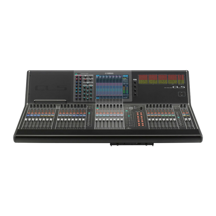
Help function at any time. About the models The CL series is available in three models: CL5, CL3, and CL1. Each model features a different number of monaural input channels and top-panel channel strips. In addition, the CL5 features an Output Meter section. -
Page 10: Controls And Functions
Meter section (for CL5 only) ➔ page 15 NOTE This illustration shows the top panel of the CL5. The CL3 and CL1 do not feature a Meter section, but enable you to install an optional MBCL meter bridge. Owner’s Manual... - Page 11 Top panel Channel Strip section [SEL] key Selects a channel that will be controlled in the Channel Strip section and on the touch screen. When a channel is selected, the key LED will light. If you control an ST IN channel in Block A of the Channel Strip section, the L channel will be routed to an odd-numbered channel, and the R channel will be routed to the adjacent even-numbered channel.
- Page 12 Controls and functions SELECTED CHANNEL section [PAN] knob When a monaural channel is selected, this knob This section enables you to set the mix parameters for the adjusts the panning of the signal sent to the STEREO currently-selected channel. bus. When a stereo channel is selected, this knob adjusts the PAN or left/right balance, whichever is selected.
-
Page 13: Display Section
Top panel Display section Centralogic section This is a touch screen that you can operate by touching the This section enables you to control up to eight channel surface of the screen. You can touch your finger to the modules that are selected from channel groups, DCA screen to select menus or set parameters. -
Page 14: User Defined Knobs
Controls and functions to the currently-selected MIX/MATRIX bus. If the USER DEFINED KNOBS graphic EQ is used, this key resets the gain to 0 dB. section Channel name display USER DEFINED knobs [A]–[D] Channel color indicator Control the parameters that have been Same as that in the Channel Strip section. -
Page 15: Master Section
On the CL5, switch the NOTE function of the knob using the Operation is guaranteed only for a connection with a USB [GAIN/PAN/ASSIGN] key flash drive. -
Page 16: Front Panel
An AES/EBU (XLR-3-32 male) jack that outputs the to separately-sold gooseneck lamps (such as the digital audio signal of a desired channel in AES/EBU Yamaha LA1L). (The CL3 includes these connectors at format. two locations. The CL1 includes one.) OMNI IN jacks... - Page 17 AC power outlet. +18 dBu) if necessary. (A fee will be charged for this The supplied AC power cable features a special procedure.) For details, contact your Yamaha dealer. latching mechanism (V-LOCK) to prevent the power Dante PRIMARY/SECONDARY connectors cable from being disconnected accidentally.
-
Page 18: Touch Screen
Touch screen Touch screen Multifunction knob operations Multifunction knobs 1–8 are used to operate knobs selected in the touch screen. A thick line will be displayed around a selected knob if it can be controlled by a multifunction knob. (Typically, a Basic touch screen knob of this type corresponds to the multifunction knob operations... -
Page 19: List Windows
The on-screen user interface List windows Popup windows Windows similar to the following enable you to select items When you press a button or field for a specific parameter in from a list, such as a list of USER DEFINED keys. a screen, a window showing detailed parameters or lists will appear. -
Page 20: Viewing The Touch Screen
Touch screen Viewing the touch screen HELP Pressing this button will show on-line help in the The touch screen of the CL series is broadly divided into main area. To view the on-line Help, first you must two areas. load the Help file from a USB flash drive. Once the Help file has been loaded, it will be kept in internal Main area Function access area... -
Page 21: Entering Names
Entering names Entering names Main area The contents of the main area will change depending on On the CL series, you can assign a name to each input the function that is currently selected. Mixing operations channel, output channel, and DCA group, and assign a title will involve mainly the following two types of screens. -
Page 22: Using The Tool Buttons
Touch screen Using the tool buttons • BS button Deletes the character to the left of the cursor (or the In some popup windows, the title bar at the top of the string of characters selected in the text box). window contains tool buttons for additional functions. -
Page 23: Using Libraries
Using libraries Using libraries [HPF/EQ popup window] [Dynamics 1/2 popup window] This section explains basic operations for libraries. In the SELECTED CHANNEL VIEW screen or the Libraries allow you to store and recall settings for the OVERVIEW screen, press the appropriate field for EQ currently-selected channel (EQ/dynamics) or rack or Dynamics 1/2. - Page 24 Touch screen Select the channel (EQ/dynamics) or rack [GEQ/EFFECT/PREMIUM RACK popup (GEQ/effect/Premium Rack) for which you window] want to recall settings. Use the rack select tabs at the bottom of the popup window to select a rack. The method of selecting a channel or rack depends on the type of popup window that is displayed.
- Page 25 Using libraries ■ Storing settings in a library RECALL button This button recalls the data selected in the list into the Open a popup window that provides the tool currently-selected channel (EQ/dynamics) or rack buttons. (GEQ/effect/Premium Rack). Select the channel (EQ/dynamics) or rack Rotate any of the multifunction knobs to (GEQ/effect/Premium Rack) for which you move the highlight line up or down to select...
-
Page 26: Initializing Settings
Touch screen Initializing settings NOTE • Even after you have stored the settings, you can edit the title of the settings by pressing the data title in the list to This section explains how to return the EQ/dynamics access the LIBRARY TITLE EDIT popup window. settings of the currently-selected channel or the effect However, you cannot edit the title of a read-only library item settings of a rack to their default state. -
Page 27: Comparing Two Settings
Comparing two settings NOTE To compare the first set of settings with the • Be aware that if you copy other settings before you paste, current settings (the second set), press the the buffer memory will be overwritten. COMPARE button. •... -
Page 28: Basic Operation Of The Cl Series
Basic operation of the CL series Basic operation of Controlling eight channels as a group (Centralogic section) the CL series The Centralogic section located below the touch screen lets you recall and simultaneously control a set of up to eight input channels, output channels, or DCA groups. -
Page 29: Using The Top Panel (Channel Strip Section)
Using the top panel (Channel Strip section) Using the top panel Press a Bank Select key to select the eight channels (other than the DCA groups) that (Channel Strip section) you want to control in the OVERVIEW screen. The Bank Select key will light. The lit status indicates The Channel Strip section of the top panel enables you to that the corresponding channels can be controlled in control the level, gain, pan, CUE, and other parameters for... - Page 30 Channel strips are categorized into four blocks; from to select the destination MIX/MATRIX buses. your left, block A, block B (Centralogic section), block C (only for CL5), and Master. ON FADER switch button Pressing this button repeatedly will switch between MIX1–16 and MIX17–24/MATRIX.
-
Page 31: Connections
This connection method is suitable for a simple system Additional information on Dante is also posted on the with a small number of devices. Yamaha Pro Audio website: However, if a large number of devices are connected, the http://www.yamahaproaudio.com/ latency value must be increased. Also, if a connection is... - Page 32 Connections ■ Connecting I/O devices to the CL series About redundant networks Make connections as shown below using the Dante A redundant network consists of two circuits, a primary connectors of the CL series and the I/O devices, and set the circuit and a secondary circuit.
-
Page 33: Audio Input/Output Connections
CL or connect speaker processor units. Refer to the Yamaha professional audio website for the most recent information on available I/O cards. http://www.yamahaproaudio.com/ Owner’s Manual... -
Page 34: Installing An Option Card
CL series, and to verify the total Caution number of Yamaha or third-party cards that can be Before connecting a separately sold mini-YGDAI I/O card installed in combination with that card. to the CL unit, you must turn off the power switches for the Yamaha website: CL and the PW800W power supply. -
Page 35: Setup
Setup Setup • LAMP Adjusts the brightness of the lamps connected to the rear panel LAMP jacks. This section explains the setup required when starting up If desired, switch between banks A and B and the CL series for the first time. This section will also discuss make settings for the other bank in the same basic operations for sending an input channel signal out way. -
Page 36: Word Clock Connections And Settings
Setup Use multifunction knobs 1–6 on the top panel In the WORD CLOCK SELECT field, select the to specify the current date and time. desired clock source. • When using the internal word clock When you have finished making settings, Press the INT 48k or INT 44.1k button. -
Page 37: Making Ha (Head Amp) Analog Gain Settings
Making HA (Head Amp) analog gain settings Making HA (Head Amp) Using the Centralogic section (settings for eight channels) analog gain settings Use the Centralogic section and the OVERVIEW screen to This section explains how to adjust the analog gain of the make head amp settings for up to eight channels. -
Page 38: Sending An Input Channel Signal To The Stereo Bus
Setup Sending an input channel Raise the fader of the currently-selected input channel to an appropriate volume. signal to the STEREO bus In this state, you should now hear sound from the speaker system that is patched to the STEREO This section explains how to adjust the level of a channel. - Page 39 Sending an input channel signal to the STEREO bus Using the Centralogic section (settings To adjust the pan/balance of the signal sent from each input channel to the STEREO bus, for eight channels) press a knob in the TO STEREO/MONO field Here is how to use the Centralogic section and of the screen to select it, and rotate the OVERVIEW screen to adjust the level and pan/balance of...
-
Page 40: Quick Guide
This section explains the general procedures in a mixing workflow. The example below is based on a system in which one CL5, one I/O device, an amplifier and speakers are connected. If there are multiple methods to achieve the Connecting I/O devices same result, this section introduces the simplest method. -
Page 41: Setting The Input Channels
Setting the input channels Setting the input channels Patching the input port Press the I/O DEVICE button in the touchscreen. Switching phantom power on or off In the upper part of the I/O Press the [SEL] key for the channel that you DEVICE screen, press the want to control in the Channel Strip section DANTE PATCH tab. -
Page 42: Applying Eq/Dynamics
Quick Guide Applying EQ/dynamics Edit the dynamics type and parameters in the DYNAMICS popup window. Use the knobs in the Centralogic section to edit the Applying EQ parameters. Press the [SEL] key of the channel that you want to control. Adjust EQ in the SELECTED CHANNEL section. -
Page 43: Applying Effects
Applying effects Applying effects Select an input source in the left column of the CH SELECT popup window, then select a channel in the right column. Using EFFECT RACK with send/return Press the RACK button in the display screen. Press the EFFECT tab. Modify the INPUT CH/OUTPUT CH patch Press the CLOSE button. - Page 44 Quick Guide Press the SENDS ON FADER button in the Inserting PREMIUM RACK processor display screen. Press the RACK button in the display screen. In the Centralogic section, press the [OUTPUT] key, then [MIX17–24/MATRIX] key. Press the PREMIUM tab. From Fx1–Fx8 routed to the Centralogic section, select and press the [SEL] key for the effect channel that you want to use.
-
Page 45: Changing The Patch Settings
Changing the patch settings Changing the patch settings In the Centralogic or Channel Strip section, select the bank that includes the channel to which you want to apply the processor. Setting up INSERT or DIRECT OUT Press the [SEL] key of the channel to which Select the bank that contains the channel for you want to apply the processor. -
Page 46: Grouping And Linking
Quick Guide Grouping and linking Changing the signal output to each output port Creating a channel link Press the SETUP button in the display screen. Press the CH JOB button in the display screen. Press the OUTPUT PORT button in the SYSTEM SETUP screen. -
Page 47: Setting A Custom Fader Bank
Setting a custom fader bank Setting a custom fader bank Using talkback Press the SETUP button in the display screen. Connect a mic to the front panel TALKBACK jack. Press the MONITOR button in the display screen. Press the USER SETUP button in the CURRENT USER area. -
Page 48: Routing The Oscillator To An Output Channel
Quick Guide Routing the oscillator to an Using scene memories output channel Storing a scene Press the MONITOR button in the display Use the [INC]/[DEC] keys in the SCENE screen. MEMORY section to select the store-destination scene number. Press the [STORE] key. Enter the scene name and comments in the SCENE STORE screen. -
Page 49: Recording And Playing Audio Using A Usb Flash Drive
Recording and playing audio using a USB flash drive Recording and playing audio Playing audio files from a USB flash drive using a USB flash drive Connect a USB flash drive that contains audio files to the CL unit. Recording audio to a USB flash drive Press the RECORDER button in the display screen. -
Page 50: Saving And Loading The Unit Settings
Quick Guide Saving and loading the unit Enter the data name and comments, then press the SAVE button. settings Loading the unit settings from a USB flash Saving the unit settings to a USB flash drive drive Press the SETUP button in the display screen. Connect a USB flash drive to the USB Press the SAVE/LOAD button. -
Page 51: Other Functions
Other functions Other functions A message indicates that the initialization process is complete. Press the EXIT button. The CL will start up in normal operating mode. NOTE • Alternatively, you can continue the operation by selecting a Initializing the unit to different menu instead of pressing the EXIT button. -
Page 52: Adjusting The Faders (Calibration Function)
Other functions Adjusting the faders After you adjust the fader position, press the [NEXT] button. (Calibration function) The process will proceed to the next fader position. Depending on the environment in which you use the CL Repeat steps 6–7 to adjust the faders for series, discrepancies may occur in the motion of the motor positions (1) through (4). -
Page 53: Troubleshooting
I/O device set to an appropriate level? ❍ Could you have turned gain compensation on while the ➥ If the power still does not turn on, contact your Yamaha dealer. analog gain was set inappropriately? Alternatively,... - Page 54 Troubleshooting High frequency range is attenuated. When you recall a scene, some channels/parameters are not updated. ❍ Could emphasis be applied? This problem will occur if ❍ Could that channel or parameter be set to Recall Safe? the input signal status does not match the emphasis data.
-
Page 55: Installing The Mbcl Meter Bridge (Option)
Installing the MBCL meter bridge (option) Installing the Tighten screws ‘A’ to secure the MBCL, starting with the upper two screws. MBCL meter Connect the MBCL connector ‘C’ to the METER port ‘D’ on the CL3/CL1, and fasten bridge (option) the locking screws. -
Page 56: Specifications
Conforms to Environments: E1, E2, E3 and E4 * The contents of this manual apply to the latest specifications as of the printing date. Since Yamaha makes continuous improvements to the product, this manual may not apply to the specifications of your particular product. To obtain the latest manual, access the Yamaha website then download the manual file. -
Page 57: Input/Output Characteristics
TTL/75Ω BNC Connector GPI (5IN/5OUT) – – D Sub Connector 15P (Female) NETWORK IEEE802.3 10BASE-T/100Base-TX RJ-45 LAMP (CL5: x3, CL3: x2, CL1: x1) – 0V-12V XLR-4-31 type USB HOST USB 2.0 – USB A Connector (Female) DC POWER INPUT –... -
Page 58: Pin Assignment
Specifications Pin Assignment DC POWER INPUT Signal Name Signal Name Signal Name Signal Name +24V GPO1 GPO2 +24V GPO3 GPO4 +24V GPO5 +24V +24V +24V GPI1 GPI2 +24V CAUTION(+) GPI3 GPI4 +24V CAUTION(–) GPI5 +24V DETECT A DETECT B DETECT GND Frame GND METER (CL3/CL1 only) Signal Name... -
Page 59: Dimensions
Dimensions Dimensions 1053 MBCL 29.2 Unit: mm Owner’s Manual... -
Page 60: Index
Master section ......15 Meter section (for CL5 only) ....15 GEQ . - Page 62 MEMO Owner’s Manual...
-
Page 63: Block Diagram
METER RACK IN L METER RACK OUT L METER RACK IN R METER RACK OUT R GEQ1-16 EFFECT A(L)/B(R) Refer to CL5/CL3/CL1 Mixer Block Diagram 2/2 EFFECT CUE FX1 IN A(L)/B(R) METER RACK IN A METER RACK OUT A To RTA... - Page 64 CUE / STEREO MONITOR CUE / SURROUND MONITOR MONITOR DELAY AUTO BYPASS CUE TRIM CUE ON (INPUT/OUTPUT/DCA) CUE OUT ON DELAY CUE L METER CUE L CUE OUT L MONITOR DELAY AUTO BYPASS CUE L BUS (MAX:1000ms) To OUTPUT PATCH CUE TRIM CUE ON METER CUE R...
-
Page 65: Level Diagram
Level Diagram Analog Digital Digital Analog MASTER Analog Digital Analog LEVEL LEVEL MASTER OUTPUT GAIN INSERT ATT. (x4) INSERT DELAY /ON PAN Adder INSERT ATT. (x4) / BAL PATCH DELAY dBFS Digital Clipping Level Max. Input [+30dBu] Max. Output [+24dBu] CASCADE IN CASCADE OUT Nominal Input [+10dBu]... - Page 66 Niederlassung und bei Yamaha Vertragshändlern in den jeweiligen Bestimmungsländern erhältlich. Pour plus de détails sur les produits, veuillez-vous adresser à Yamaha ou au distributeur le plus proche de vous figurant dans la liste suivante. Para detalles sobre productos, contacte su tienda Yamaha más cercana o el distribuidor autorizado que se lista debajo.
- Page 67 Yamaha Pro Audio Global Web Site http://www.yamahaproaudio.com/global/en/ Yamaha Manual Library http://www.yamaha.co.jp/manual/ Manual Development Department © 2012-2015 Yamaha Corporation Published 1/2015 IPTO-E0 Printed in Japan ZC58320...