Yamaha RX-V365 Owner's Manual
Hide thumbs
Also See for RX-V365:
- Owner's manual (104 pages) ,
- Service manual (100 pages) ,
- Specifications (2 pages)
Table of Contents
Advertisement
Quick Links
Advertisement
Chapters
Table of Contents
Troubleshooting

Related Manuals for Yamaha RX-V365


Summary of Contents for Yamaha RX-V365
- Page 1 RX-V365 AV Receiver OWNER’S MANUAL...
- Page 2 12 Only voltage specified on this unit must be used. Using this unit with a higher voltage than specified is dangerous and may cause fire, damage to this unit, and/or personal injury. Yamaha will not be held responsible for any damage resulting from use of this unit with a voltage other than specified.
-
Page 3: Table Of Contents
Contents INTRODUCTION ADVANCED OPERATION Features..............2 Set menu ..............30 Supplied accessories ..........2 Using set menu............31 Functional overview..........3 1 SOUND MENU............ 31 2 INPUT MENU............33 Front panel ..............3 3 OPTION MENU ........... 34 Front panel display............. 4 Remote control features ........ -
Page 4: Introduction
◆ SCENE template customizing capability Check that you received all of the following parts. ❏ Remote control Sound field programs ◆ Proprietary Yamaha technology for the creation of surround ❏ Batteries (2) (AAA, R03, UM-4) field ❏ AM loop antenna ◆... -
Page 5: Functional Overview
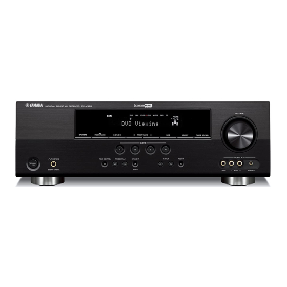
Functional overview Front panel VOLUME OPTIMIZER MIC EDIT SPEAKERS PRESET/TUNING A/B/C/D/E PRESET/TUNING BAND MEMORY TUNING AUTO/MAN'L SCENE VIDEO AUX PHONES TONE CONTROL PROGRAM STRAIGHT INPUT NIGHT STANDBY SILENT CINEMA EFFECT VIDEO AUDIO PORTABLE STANDBY/ON VOLUME control Turns on this unit, or sets it to standby mode (see page 15). Adjusts the volume level of this unit (see page 18). -
Page 6: Front Panel Display
Functional overview Front panel display V-AUX DTV/CBL MD/CD-R TUNER VOLUME AUTO TUNED STEREO MEMORY YPAO VIRTUAL SILENT CINEMA PRESET NIGHT SLEEP ENHANCER MUTE DIGITAL L C R Decoder indicator Input channel and speaker indicators Lights up when any of the decoders of this unit functions. LFE indicator ENHANCER indicator L C R... -
Page 7: Remote Control
Functional overview Remote control Press this button before you control this unit (see page 18). SCENE 1/2/3/4 Recalls an input source and a sound field program assigned to POWER POWER STANDBY POWER each SCENE button (see page 22). BAND LEVEL TITLE MUTE Selects the speaker that you want to adjust (see page 20). -
Page 8: Rear Panel
Functional overview Rear panel ANTENNA SPEAKERS SURROUND CENTER FRONT B DTV/CBL HDMI COMPONENT VIDEO DTV/CBL MONITOR DIGITAL INPUT VIDEO DTV/CBL MONITOR UNBAL. OPTICAL MULTI CH INPUT AUDIO OUTPUT DTV/CBL FRONT SURROUND CENTER (PLAY) CD-R (REC) DTV/ WOOFR COAXIAL FRONT A SUBWOOFER COMPONENT VIDEO jacks MULTI CH INPUT jacks... -
Page 9: Quick Start Guide
Quick start guide The following steps describe the easiest way to operate this unit. See the related pages for details on the operation and settings. Step 1: Check the items Step 3: Connect your components In these steps, you need the following items which are not Connect your TV, DVD player or other components. -
Page 10: Preparation
PREPARATION Preparation of remote control Installing batteries in the remote control Using the remote control The remote control transmits a directional infrared ray. Be sure to aim the remote control directly at the remote control sensor on this unit during operation. 30º... -
Page 11: Connections
Subwoofer (SW) FRONT A The use of a subwoofer with a built-in amplifier, such as the Yamaha Active Servo Processing Subwoofer System, is effective not only for reinforcing bass frequencies from any or all channels, but also for high fidelity sound reproduction of the LFE (low-frequency effect) channel included in Dolby Digital and DTS sources. - Page 12 Connections ■ Connecting to the FRONT A terminals Speakers Jacks on this unit a Front speaker (A) Right* FRONT A (R) b Front speaker (A) Left* FRONT A (L) c Surround speaker Right SURROUND (R) Red: positive (+) d Surround speaker Left SURROUND (L) Black: negative (–) e Center speaker...
-
Page 13: Connecting Video Components
Connections VIDEO jacks Connecting video components For conventional composite video signals transmitted via composite video cables. Information on jacks and cable plugs COMPONENT VIDEO jacks For component signals, separated into the luminance (Y) Audio jacks and cable plugs and chrominance (P ) video signals transmitted on separate wires of component video cables. -
Page 14: Connecting A Tv Monitor Or Projector
Connections Connecting a TV monitor or projector Make sure that this unit and other components are unplugged from the AC wall outlets. Note • If you turn off the video monitor connected to the HDMI OUT jack via a DVI connection, the connection may fail. In this case, the HDMI indicator flashes irregularly. -
Page 15: Connecting Other Components
Connections Connecting other components Connecting audio and video components This unit has three types of audio jacks, two types of video jacks and HDMI jacks. You can choose the connection method depending on the component to be connected. ■ Connecting example (connecting a DVD player) ANTENNA DTV/CBL HDMI... -
Page 16: Using The Video Aux Jacks On The Front Panel
Connections Component Signal type Jacks on component Jacks on this unit DVD recorder Video HDMI out* HDMI (DVR)* Video out (composite) VIDEO (DVR IN) Audio Audio out (analog)* AUDIO (IN (PLAY))* Audio recording Audio in (analog)* AUDIO (OUT (REC))* Video recording Video in (composite)* VIDEO (DVR OUT)* CD player... -
Page 17: Connecting The Fm And Am Antennas
• A properly installed outdoor antenna provides clearer reception than an indoor one. If you experience poor reception quality, install an outdoor antenna. Consult the nearest authorized Yamaha dealer or service center about outdoor antennas. • The AM loop antenna should always be connected, even if an outdoor AM antenna is connected to this unit. -
Page 18: Optimizing The Speaker Setting For Your Listening Room (Ypao)
Optimizing the speaker setting for your listening room (YPAO) This unit has the Yamaha Parametric Acoustic Optimizer (YPAO). With the YPAO, this unit automatically adjusts output characteristics of your speakers based on speaker positions, speaker performances, and acoustic characteristics of the room. - Page 19 Optimizing the speaker setting for your listening room (YPAO) ■ If an error screen appears Notes If this unit detects the potential problems, an error • During the automatic setup procedure, do not perform any message appears on the front panel display during the operation on this unit.
-
Page 20: Basic Operation
BASIC OPERATION Playback Rotate PVOLUME (or press mVOLUME +/–) Caution Extreme caution should be exercised when you play to adjust the volume to the desired output back CDs encoded in DTS. If you play back a CD level. encoded in DTS on a DTS-incompatible CD player, you will only hear some unwanted noise that may damage your speakers. -
Page 21: Additional Operations
Playback ■ Selecting the component connected to the Guide to contents MULTI CH INPUT jacks as the input source Use this feature to select the component connected to the When you want... See page MULTI CH INPUT jacks (see page 14) as the input source. -
Page 22: Using Audio Features
Playback Using audio features • Once you press jBAND LEVEL TITLE on the remote control, you can also select the speaker by pressing lk / n. Use the following features to adjust the audio output or • The available speaker channels differ depending on the speaker settings. - Page 23 Playback ■ Using the sleep timer Press ll / h to adjust the effect level while Use this feature to automatically set this unit to the “NIGHT:CINEMA” or “NIGHT:MUSIC” is standby mode after a certain amount of time. The sleep displayed on the front panel display.
-
Page 24: Selecting The Scene Templates
Selecting the SCENE templates Just by pressing one SCENE button, you can recall your Selecting the desired SCENE template favorite input source and sound field program according to the SCENE template that has been assigned to the SCENE button. The SCENE templates are built combinations of Press and hold the desired JSCENE (or input sources and sound field programs. - Page 25 Selecting the SCENE templates Which SCENE template would you like to select? The following tables indicate preset SCENE template descriptions. Select the corresponding SCENE templates for the desired source. The illustrations of the SCENE button in the following table indicate that the SCENE templates in those cells are assigned to the SCENE buttons, respectively.
-
Page 26: Creating Your Original Scene Templates
Selecting the SCENE templates Press lk / n to select the desired parameter Creating your original SCENE of the SCENE template and then ll / h to templates select the desired value of the selected You can create your original SCENE templates for each parameter. -
Page 27: Using Remote Control On The Scene Feature
Selecting the SCENE templates Using remote control on the SCENE feature Controlling the input source components in the SCENE mode You can operate both this unit and the input source component by using the remote control. You must set the appropriate remote control code for each input source in advance (see page 38). -
Page 28: Sound Field Programs
This unit is also equipped with a Yamaha digital sound • Sound field programs cannot be selected when the component connected to the MULTI CH INPUT jacks is selected as the input source (see field processing (DSP) chip containing several sound field page 19). - Page 29 Sound field programs ■ Selecting decoders for 2-channel sources CT WIDTH Center width (surround decode mode) Function: Adjusts the center image from all three front Signals input from 2-channel sources can also be played speakers to varying degrees. A larger value back on multi-channels.
-
Page 30: Fm/Am Tuning
FM/AM tuning Overview To begin automatic tuning, press FPRESET/TUNING l / h once. To tune You can use two tuning modes to tune into a desired FM/ into the desired station manually, press AM station: FPRESET/TUNING l / h repeatedly. ■... - Page 31 FM/AM tuning Press EA/B/C/D/E (or ll / h) repeatedly to • You can select the preset station group and the preset station number where the first received station will be stored by pressing EA/B/C/D/E select the desired preset station group (A to and then FPRESET/TUNING l / h.
-
Page 32: Advanced Operation
ADVANCED OPERATION Set menu You can use the following parameters in the set menu to adjust a variety of system settings and customize the way this unit operates. Change the initial settings to reflect the needs of your listening environment. AUTO SETUP Auto setup Use this feature to automatically adjust speaker and system parameters (see page 16). -
Page 33: Using Set Menu
Set menu Using set menu 1 SOUND MENU Use the remote control to access and adjust each Use this menu to manually adjust any speaker settings or parameter. compensate for video signal processing delays when using LCD monitors or projectors. •... - Page 34 Set menu LFE signals output Notes Choice Subwoofer Front speakers Other speakers • The available speaker channels differ depending on the setting of the speakers. BOTH* Output No output No output • This does not affect recorded material. C)SP DISTANCE Speaker distance SWFR Output...
-
Page 35: Input Menu
Set menu ■ ■ TEST A.DELAY Test tone Audio delay Use this feature to make adjustments for “CENTER GEQ” Use this feature to delay the sound output and synchronize while listening to a test tone. it with the video image. This may be necessary for certain LCD monitors or projectors. -
Page 36: Option Menu
Set menu B)INPUT RENAME D)DECODER MODE Input rename Decoder mode ■ Decoder select mode Use this feature to change the name of the input source that appears on the front panel display. Use this feature to designate the default decoder mode for the input sources connected to the DIGITAL INPUT The following is an example where “DVD”... - Page 37 Set menu Note • When “MEM.GUARD” is set to “ON,” you cannot select and adjust any other set menu items. C)AUDIO SELECT Audio select Use this feature to designate the default audio input jack select setting for the input sources. Choice Function AUTO*...
-
Page 38: Remote Control Features
Remote control features In addition to controlling this unit, the remote control can also operate other audiovisual components made by Yamaha and other manufacturers. To control your TV or other components, you must set up the appropriate remote control code for each input source (see page 38). - Page 39 Remote control features ■ Controlling other components Press one of the input selector buttons (f) or A to E buttons to control other components. You must set the appropriate remote control code for each input source in BAND LEVEL VOLUME TITLE MENU advance (see page 38).
-
Page 40: Setting Remote Control Codes
Note display, and the remote control codes previously set • You may not be able to operate your Yamaha component even if a are cleared and reset to the initial factory settings. Yamaha remote control code is preset as listed above. In this case, try setting another Yamaha remote control code. -
Page 41: Advanced Setup
Advanced setup This unit has additional menus that are displayed on the front panel display. The advanced setup menu offers additional operations to adjust and customize the way this unit operates. Change the initial settings (indicated by (*) in this following parameter) to reflect the needs of your listening environment. -
Page 42: Additional Information
Refer to the table below when this unit does not function properly. If the problem you are experiencing is not listed below or if the instruction below does not help, turn off this unit, disconnect the power cable, and contact the nearest authorized Yamaha dealer or service center. ■... - Page 43 Troubleshooting Problem Cause Remedy page Only the center When playing a monaural source with a speaker outputs CINEMA DSP program, the source signal substantial sound. is directed to the center channel, and the front and surround speakers output effect sounds. No sound is heard “CENTER”...
- Page 44 Troubleshooting Problem Cause Remedy page This unit does not The internal microcomputer has been Disconnect the power cable from the AC wall outlet — operate properly. frozen by an external electric shock (such and then plug it in again after about 30 seconds. as lightning or excessive static electricity) or by a power supply with low voltage.
- Page 45 Troubleshooting Problem Cause Remedy page The desired station The signal is weak or the antenna Tighten the AM loop antenna connections and — cannot be tuned into connections are loose. orient it for the best reception. with the automatic Use the manual tuning method. tuning method.
-
Page 46: Resetting The System
Troubleshooting After AUTO SETUP Warning message Cause Remedy page PHASE REVERSED Speaker polarity is not correct. This Check the speaker connections for proper polarity (+ message may appear depending on the or –). speakers even when the speakers are connected correctly. DISTANCE ERROR The distance between the nearest speaker Bring the speaker closer to the listening position. -
Page 47: Glossary
5-channel playback with 2 front left and right heard. Based on a wealth of actually measured data, Yamaha channels, 1 center channel, and 2 surround left and right channels... -
Page 48: Specifications
Specifications AUDIO SECTION VIDEO SECTION • Minimum RMS Output Power for Front, Center, Surround • Signal Level Composite ..............1 Vp-p/75 Ω [U.S.A. and Canada models] 1 kHz, 0.9% THD, 8 Ω ..........100 W/ch Component ....1 Vp-p/75 Ω (Y), 0.7 Vp-p/75 Ω (P [Other models] •... -
Page 49: Index
Index ■ Numerics Control buttons, remote control ....... 5 Initial volume ..........33 Creating original SCENE templates ....24 Initializing ............. 39 1 SOUND MENU ........30, 31 CROSSOVER ..........32 Input assignment ........... 33 2 INPUT MENU ........30, 33 Crossover ............32 Input channel and speaker indicators .... - Page 50 Selecting the night listening mode ....20 ■ Selecting the SCENE templates .....22 Set menu ............30 Yamaha Parametric Room Acoustic Set this unit to the standby mode ....15 Optimizer ..........16 Setting input source of the customized SCENE YPAO ............16 template on the remote control ....25...
-
Page 51: List Of Remote Control Codes
List of remote control codes 2078 Yamaha 2000, 2001, 2003, Microsoft 2132 Blu-ray Player Medion 2072 2030, 2101 Mind 2132 Micromaxx 2072 Yukai 2078 Samsung 2137 Niveus Media 2132 Micromedia 2073 Zenith 2038, 2047, 2073 Northgate 2132 CD Player Microstar... - Page 52 Akai 0059, 0065, 0127, Cascade 0208 Envision 0060, 0061 Hisawa 0209, 0218 0129, 0130, 0200, Cathay 0213, 0217 Erres 0213, 0217 Hitachi 0006, 0014, 0015, 0204, 0208, 0209, 0127 0080 0016, 0042, 0060, 0213, 0217, 0218, Celebrity 0059 Etron 0208 0061, 0095, 0105, 0255 Centurion...
- Page 53 Lenco 0208 0026, 0053, 0060, 0182, 0194, 0195, Sanyo 0020, 0021, 0022, Lenoir 0207, 0208 0061, 0096, 0127 0211, 0213, 0216, 0049, 0060, 0064, Lesa 0214 Neckermann 0205, 0207, 0210, 0217, 0250 0127, 0128, 0200, Leyco 0206, 0213, 0217 0213, 0217, 0255 Plantron 0206, 0213 0203, 0207, 0215...
- Page 54 White Westinghouse Amstrad 1042 1045 Tatung 0127, 0204, 0207, 0200, 0207, 0217 Anitech 1050 Goodmans 1042, 1045, 1050, 0213, 0217, 0237 Yamaha 0000, 0001, 0002, 1045, 1046 1069 0206, 0208 0003, 0004, 0005, Asha 1002, 1014 Gradiente 1005 Teac 0127...
- Page 55 RX-V365 List of remote control codes The following remote control codes are available in addition to “List of remote control codes” at the end of the owner’s manual. Panasonic 1004, 1020, 1034, Saisho 1044, 1050 Tashiko 1003, 1042 1040, 1048, 1054,...
- Page 56 © 2009 Yamaha Corporation All rights reserved. Printed in China WQ95900...
- Page 57 Owner’s Manual NS-50F SPEAKER SYSTEM Thank you for choosing a Yamaha speaker system. Caution ■ Read the following before using the speaker: • To assure the finest performance, please read • Secure placement or installation is the owner’s this manual carefully. Keep it in a safe place for responsibility.
- Page 58 Precautions When Supplied Accessories Positioning the Speakers • Speaker cable (4 m) The speaker is constructed with the majority of the weight located in its upper portion, and is thus susceptible to falling over if proper care is not taken to insure its stability. If the speaker falls over, it may damage the speaker or be the cause of ✕...
-
Page 59: Placing The Speakers
Placing the Speakers Attaching the Stands Place the speakers on a sturdy, vibration-free When placing the speakers, be sure to use the surface. stands to increase stability. Use the 8 specified holes located on the base of ■ Using as Normal Stereo Speakers the speaker. -
Page 60: Connecting Your Speakers
Connecting Your Notes: Speakers • Make sure that the bare wires are not touching each other as this could damage the speaker and amplifier. Always turn off your amplifier or receiver • Connect one speaker to the left terminals of your before making any connections. - Page 61 YAMAHA ELECTRONICS (UK) LTD. YAMAHA HOUSE, 200 RICKMANSWORTH ROAD WATFORD, HERTS WD18 7GQ, ENGLAND YAMAHA SCANDINAVIA A.B. J A WETTERGRENS GATA 1, BOX 30053, 400 43 VÄSTRA FRÖLUNDA, SWEDEN YAMAHA MUSIC AUSTRALIA PTY, LTD. 17-33 MARKET ST., SOUTH MELBOURNE, 3205 VIC., AUSTRALIA...
- Page 62 NS-P60 HOME CINEMA CENTER & EFFECT SPEAKERS “NS-P60” is the package number which includes the YAMAHA speaker system NS-C55 and NS-E55. Thank you for selecting this Yamaha NS-P60 speaker system. NS-C55 Natural Sound Center Speaker System PLACING THE SPEAKER PRECAUTIONS...
- Page 63 CONNECTION TO YOUR AMPLIFIER SPECIFICATIONS NS-C55 Type......2-way 3-speaker acoustic-suspension BEFORE MAKING CONNECTIONS, MAKE SURE THAT speaker system THE AMPLIFIER IS SWITCHED OFF. Magnetic-shielding type Speaker Unit ........10 cm cone woofer x 2 CONNECTIONS 2.2 cm dome tweeter ● Connect the screw-type input terminals at the rear of the Input Terminal .............Screw-type speaker to the speaker output terminals of your amplifier Impedance ..............6 ohm...
-
Page 64: Setting Up The Speakers
● Do not fasten the speakers to wall with nails, adhesives, YAMAHA shall not be liable for any accident caused by improper placement or installation of the speak- or other unsound hardware. Long term use and vibra- ers. - Page 65 CONNECTION TO YOUR AMPLIFIER SPECIFICATIONS Type......2-way 2-speaker acoustic-suspension BEFORE MAKING CONNECTIONS, MAKE SURE THAT speaker system THE AMPLIFIER IS SWITCHED OFF. Loosen Speaker Unit ..........10 cm cone woofer Tighten 2.2 cm dome tweeter CONNECTIONS Input Terminal .............Screw-type ● Connect the screw-type input terminals at the rear of the Black (–) Impedance ..............6 ohm speakers to the speaker output terminals of your amplifi-...
- Page 66 YST-SW216 Subwoofer System OWNER’S MANUAL...
-
Page 67: Important Safety Instructions
IMPORTANT SAFETY INSTRUCTIONS Read these instructions. Keep these instructions. Heed all warnings. Follow all instructions. Do not use this apparatus near water. Clean only with dry cloth. Do not block any ventilation openings. Install in accordance with the manufacturer’s instructions. Explanation of Graphical Symbols Do not install near any heat sources such as radiators, heat registers, stoves, or other apparatus (including... - Page 68 If you can not locate the appropriate retailer, please contact Yamaha Electronics Corp., U.S.A. 6660 Orangethorpe Ave, Buena Park, CA 90620. The above statements apply ONLY to those products distributed by Yamaha Corporation of America or its subsidiaries.
- Page 69 Thank you for selecting this YAMAHA subwoofer system. CAUTION: Read this before operating your unit Please read the following operating precautions • Never put a hand or a foreign object into the YST port before use. YAMAHA will not be held responsible located on the right side of this unit.
- Page 70 AC main supply. Voltages are 110-120/220-240 V AC, 50/60 Hz. CONTENTS FEATURES CAUTION ..............iii • This subwoofer system employs Advanced Yamaha Active Servo Technology II which Yamaha has FEATURES ..............1 developed for reproducing higher quality super-bass sound.
-
Page 71: Placement
PLACEMENT One subwoofer will have a good effect on your audio system, however, the use of two subwoofers is recommended to obtain more effect. If using one subwoofer, it is recommended to place it on the outside of either the right or the left front speaker. (See fig. -
Page 72: Connections
Connecting to line output (pin jack) terminals of the amplifier • To connect with a YAMAHA DSP amplifier (or AV receiver), connect the SUBWOOFER (or LOW PASS etc.) terminal on the rear of the DSP amplifier (or AV receiver) to the /MONO INPUT 2 terminal of the subwoofer. - Page 73 CONNECTIONS ■ Using one subwoofer Subwoofer Mono pin cable (not included) OUTPUT INPUT HIGH OUTPUT INPUT HIGH TO SPEAKERS TO SPEAKERS /MONO VOLUME HIGH LOW INPUT 1 FROM AMPLIFIER Audio pin cable /MONO (not included) POWER HIGH LOW INPUT 1 FROM AMPLIFIER To AC outlet Amplifier...
-
Page 74: Connecting To Speaker Output Terminals Of The Amplifier
CONNECTIONS Connecting to speaker output terminals of the amplifier Select this method if your amplifier has no line output (pin jack) terminal. If your amplifier has two sets of front speaker output terminals and both terminals can output sound signals simultaneously. •... - Page 75 CONNECTIONS If your amplifier has only one set of front speaker output terminals. Connect the speaker output terminals of the amplifier to the INPUT 1 terminals of the subwoofer, and connect the OUTPUT terminals of the subwoofer to the front speakers. ■...
-
Page 76: Connecting To The Input 1/ Output Terminals
CONNECTIONS Connecting to the INPUT 1/OUTPUT Plug in the subwoofer to the AC outlet terminals of the subwoofer After all connections are completed, plug in the subwoofer and other audio/video components to the AC outlet. For connection, keep the speaker cables as short as possible. -
Page 77: Controls And Their Functions
CONTROLS AND THEIR FUNCTIONS Subwoofer rear panel OUTPUT HIGH INPUT TO SPEAKERS OUTPUT INPUT HIGH TO SPEAKERS /MONO VOLUME HIGH LOW INPUT 1 FROM AMPLIFIER /MONO POWER VOLUME HIGH LOW INPUT 1 FROM AMPLIFIER POWER switch HIGH CUT switch Press this switch to the ON position to turn on the Selects the high frequency cut off point. -
Page 78: Frequency Characteristics
ADJUSTING THE SUBWOOFER BEFORE USE Before using the subwoofer, adjust the subwoofer to obtain the optimum volume and tone balance between the subwoofer and the front speakers by following the procedures described below. Subwoofer rear panel OUTPUT HIGH INPUT TO SPEAKERS OUTPUT INPUT HIGH... - Page 79 ADJUSTING THE SUBWOOFER BEFORE USE Frequency response The frequency response of this subwoofer HIGH CUT HIGH HIGH CUT 500Hz The figures below show the optimum adjustment of each control and the frequency characteristics when this subwoofer is combined with a typical front speaker system. ■...
-
Page 80: Advanced Yamaha Active Servo Technology Ii
ADVANCED YAMAHA ACTIVE SERVO TECHNOLOGY II In 1988, Yamaha brought to the marketplace speaker reproduction from much smaller cabinets than was systems utilizing YST (Yamaha Active Servo Technology) previously possible. to give powerful, high quality bass reproduction. This Yamaha’s newly developed Advanced YST II adds many... -
Page 81: Troubleshooting
Refer to the chart below when this unit does not function properly. If the problem you are experiencing is not listed below or if the instructions given below do not help, disconnect the power cord and contact your authorized YAMAHA dealer or service center. -
Page 82: Specifications
SPECIFICATIONS Type ..Advanced Yamaha Active Servo Technology II Power Consumption ..........45 W Driver........25 cm (10”) cone woofer Dimensions (W x H x D) Magnetic shielding type ........340 mm x 340 mm x 385 mm (13-3/8” x 13-3/8” x 15-5/32”) Output Power .... - Page 85 YAMAHA ELECTRONICS (UK) LTD. YAMAHA HOUSE, 200 RICKMANSWORTH ROAD WATFORD, HERTS WD18 7GQ, ENGLAND YAMAHA SCANDINAVIA A.B. J A WETTERGRENS GATA 1, BOX 30053, 400 43 VÄSTRA FRÖLUNDA, SWEDEN YAMAHA MUSIC AUSTRALIA PTY, LTD. 17-33 MARKET ST., SOUTH MELBOURNE, 3205 VIC., AUSTRALIA...