Table of Contents
Advertisement
RX-V361/HTR-6030/DSP-AX361
This manual has been provided for the use of authorized YAMAHA Retailers and their service personnel.
It has been assumed that basic service procedures inherent to the industry, and more specifically YAMAHA Products, are already
known and understood by the users, and have therefore not been restated.
WARNING:
IMPORTANT:
The data provided is believed to be accurate and applicable to the unit(s) indicated on the cover. The research, engineering, and
service departments of YAMAHA are continually striving to improve YAMAHA products. Modifications are, therefore, inevitable
and specifications are subject to change without notice or obligation to retrofit. Should any discrepancy appear to exist, please
contact the distributor's Service Division.
WARNING:
IMPORTANT:
I CONTENTS
To Service Personnel .......................................... 2
Front Panels ........................................................ 3–4
Rear Panels .......................................................... 5–9
Remote Control Panels ...................................... 9
SPECIFICATIONS / 参考仕様 ................................ 10–12
Internal View ......................................................... 13
DISASSEMBLY PROCEDURES / 分解手順 .......... 14–16
ファームウェアの書き込み ..................................... 17–19
SELF DIAGNOSIS FUNCTION (DIAG) /
自己診断機能(ダイアグ) ..................................... 20–37
1 0 1 0 4 0
AV RECEIVER/AV AMPLIFIER
IMPORTANT NOTICE
Failure to follow appropriate service and safety procedures when servicing this product may result in personal
injury, destruction of expensive components, and failure of the product to perform as specified. For these reasons,
we advise all YAMAHA product owners that any service required should be performed by an authorized
YAMAHA Retailer or the appointed service representative.
The presentation or sale of this manual to any individual or firm does not constitute authorization, certification or
recognition of any applicable technical capabilities, or establish a principle-agent relationship of any form.
Static discharges can destroy expensive components. Discharge any static electricity your body may have
accumulated by grounding yourself to the ground buss in the unit (heavy gauge black wires connect to this buss).
Turn the unit OFF during disassembly and part replacement. Recheck all work before you apply power to the unit.
2007
This manual is copyrighted by YAMAHA and may not be copied or
redistributed either in print or electronically without permission.
SERVICE MANUAL
Display Data ........................................................... 39
Ic Data ................................................................. 40–54
Block Diagrams .............................................. 55–56
Pin Connection Diagrams .................................. 57
Printed Circuit Boards................................ 58–70
Schematic Diagrams ...................................... 71–80
Replacement Parts List .............................. 81–95
Remote Control .............................................. 96–98
Advanced setup / すべての設定を初期設定に戻す ....... 99
All rights reserved.
P.O.Box 1, Hamamatsu, Japan
'07.02
Advertisement
Table of Contents

Related Manuals for Yamaha RX-V361


Summary of Contents for Yamaha RX-V361
-
Page 1: Service Manual
This manual has been provided for the use of authorized YAMAHA Retailers and their service personnel. It has been assumed that basic service procedures inherent to the industry, and more specifically YAMAHA Products, are already known and understood by the users, and have therefore not been restated. -
Page 2: To Service Personnel
RX-V361/HTR-6030/DSP-AX361 I TO SERVICE PERSONNEL AC LEAKAGE WALL EQUIPMENT TESTER OR 1. Critical Components Information OUTLET UNDER TEST EQUIVALENT Components having special characteristics are marked s and must be replaced with parts having specifications equal to those originally installed. 2. Leakage Current Measurement (For 120V Models Only) -
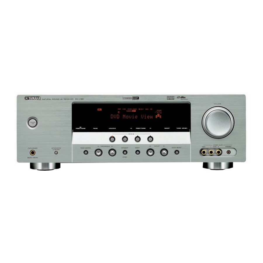
Page 3: Front Panels
RX-V361/HTR-6030/DSP-AX361 I FRONT PANELS RX-V361 (U, C models) RX-V361 (R, T, K, A, B, G, E, L models) HTR-6030 (U, C models) - Page 4 RX-V361/HTR-6030/DSP-AX361 HTR-6030 (R, T, K, A, G, E models) DSP-AX361 (J model)
-
Page 5: Rear Panels
RX-V361/HTR-6030/DSP-AX361 I REAR PANELS RX-V361 (U, C models) RX-V361 (R model) RX-V361 (T model) - Page 6 RX-V361/HTR-6030/DSP-AX361 RX-V361 (K model) RX-V361 (A model) RX-V361 (B, G, E models)
- Page 7 RX-V361/HTR-6030/DSP-AX361 RX-V361 (L model) HTR-6030 (U, C models) HTR-6030 (R model)
- Page 8 RX-V361/HTR-6030/DSP-AX361 HTR-6030 (T model) HTR-6030 (K model) HTR-6030 (A model)
-
Page 9: Remote Control Panels
RX-V361/HTR-6030/DSP-AX361 I REMOTE CONTROL PANELS • RAV311 • RAV312 HTR-6030 (G, E models) RX-V361 (R, T, K, A, L models) RX-361 (U, C models) HTR-6030 (R, T, K, A models) HTR-6030 (U, C models) DSP-AX361 (J model) DSP-AX361 (J model) •... -
Page 10: Specifications
Boost/Cut ..........±10 dB (100 Hz) は、ドルビーラボラトリーズの商標です。 TREBLE Boost/Cut ..........±10 dB (20 kHz) Filter Characteristics / フィルタ特性 FRONT, CENTER, SURROUND small (H.P.F.) “SILENT CINEMA” is a trademark of YAMAHA CORPORATION..fc=40/60/80/90/100/110/120/160/200 Hz, 12 dB/oct. 「サイレントシネマ SILENT CINEMA 」 はヤマハ株式会社の SUBWOOFER (L.P.F.) 登録商標です。... - Page 11 RX-V361/HTR-6030/DSP-AX361 • SCENE TEMPLATE Select (Default) Program SCENE name Contents Source Mode Sub-mode U, C models R, T, K, A, B, G, E, L, J models DVD Viewing Movie STRAIGHT – O (SCENE 1) DVD Movie Viewing MOVIE THEATER Movie Dramatic...
- Page 12 RX-V361/HTR-6030/DSP-AX361...
-
Page 13: Internal View
RX-V361/HTR-6030/DSP-AX361 I INTERNAL VIEW • Top view Power Transformer OPERATION (3) P.C.B. OPERATION (5) P.C.B. (R, L models) MAIN (3) P.C.B. Tuner MAIN (2) P.C.B. (U, C, R, T, K, A, B, G, E, L models) D-VIDEO P.C.B. (J model) DSP P.C.B. -
Page 14: Disassembly Procedures
RX-V361/HTR-6030/DSP-AX361 I DISASSEMBLY PROCEDURES / 分解手順 (Remove parts in the order as numbered.) (番号順に部品を取り外してください。) AC電源コンセントから、電源コードを抜いてください。 Disconnect the power cable from the AC outlet. 1. トップカバーの外し方 1. Removal of Top Cover a. 1 のネジ4本、 2 のネジ4本、 3 のネジ1本を外します。 a. Remove 4 screws (1), 4 screws (2) and 1 screw (3). - Page 15 RX-V361/HTR-6030/DSP-AX361 MAIN (2) P.C.B. (U, C, R, T, K, A, B, G, E, L models) D-VIDEO P.C.B. (J model) Rear panel Cord stopper リ アパネル コー ドス ト ッパー CB305 (J model) CB181 (U, C, R, T, K, A, B, G, E, L models) DSP P.C.B.
- Page 16 RX-V361/HTR-6030/DSP-AX361 When checking the P.C.B. P.C.B.をチェックする場合 a. Remove the Top cover. (Fig. 1) a. トップカバーを外します。 (Fig. 1) b. 7 のネジ3本を外します。 (Fig. 3) b. Remove 3 screws (7). (Fig. 3) c. 0 のネジ5本、 A のネジ4本を外します。 (Fig. 4) c. Remove 5 screws (0) and 4 screws (A). (Fig. 4) d.
-
Page 17: Updating Firmware
RX-V361/HTR-6030/DSP-AX361 I UPDATING FIRMWARE / ファームウェアの書き込み 下記部品をサービス部品に交換した場合、最新のファーム After replacing the following parts with the replacement part, be sure to write the latest firmware. ウェアの書き込みを行ってください。 ・ DSP P.C.B. • DSP P.C.B. ・ IC201 ( DSP P.C.B.) • IC201 (DSP P.C.B.) G Required Tools ●... - Page 18 RX-V361/HTR-6030/DSP-AX361 2. While pressing the “STANDBY/ON” key and 2. 本機の “STANDBY/ON” キーと、 “SPEAKERS A/B/ OFF” キーを押しながら、本機の電源コードをACコ “SPEAKERS A/B/OFF” key of the main unit simul- taneously, connect the power cable of the main unit ンセントに接続します。 (Fig. 2) FIRMWARE UPDATEモードが起動し、 “SPDIF to the AC outlet. (Fig. 2) Upgrade”...
- Page 19 RX-V361/HTR-6030/DSP-AX361 When the version of the firmware to be written ※ 本機に既存のファームウェアと、書き込もうと しているファームウェアのバージョンが同じ場 is the same as the one existing in the main unit, “Same Version”, “Please...” and “Turn off!!” are 合、 “Same Version” 、 “Please...” 、 “Turn off!!” の表示が繰り返されます。 (バージョンアップの...
- Page 20 RX-V361/HTR-6030/DSP-AX361 I SELF DIAGNOSIS FUNCTION (DIAG)/自己診断機能 (ダイアグ) This unit has self diagnosis functions that are intended for 本機には、検査、測定、不良個所の発見を目的にした自己 診断機能 (ダイアグ) があります。 inspection, measurement and location of faulty point. There are 18 DIAG menu items, each of which has sub- ダイアグメニューは1 8 個あり、そのそれぞれにサブメ...
- Page 21 RX-V361/HTR-6030/DSP-AX361 DIAG menu Sub-menu IF STATUS IF 1 (Not applied to these models.) IF 2 IF 3 IF 4 IF 5 IF 6 IF 7 IF 8 IF 9 IF 10 IF 11 IF 12 IF 13 IF 14 IF 15...
- Page 22 RX-V361/HTR-6030/DSP-AX361 • Starting DIAG ● ダイアグの起動 Press the “STANDBY/ON” key while simultaneously 本体の下図に示すキーを同時に押しながら “STANDBY/ ON” キーを押すと、ダイアグが起動します。 pressing those two keys of the main unit as indicated in the figure below. Keys of main unit / 本機キー Turn on the power while pressing these keys. / これらのキーを同時に押しながら、電源オンする。...
- Page 23 RX-V361/HTR-6030/DSP-AX361 プロテクション履歴が無い場合: When there is no history of protection function: Opening message / オープニング表示 DIAG menu display / ダイアグメニュー表示 When there is no protection history プロテクション履歴が無い場合 After a few seconds / 数秒後 NO PROTECTION 1.ANLOG BYPASS プロテクション履歴がある場合: When there is a history of protection function: When there is a history of protection function due 過電流によるプロテクション履歴がある場合...
- Page 24 RX-V361/HTR-6030/DSP-AX361 電源部の電圧異常によるプロテクション履歴がある場合 When there is a history of protection function due to abnormal voltage in the power supply section PRV PRT:xxx AD value when the protection function is working プロテクション動作時のA/D値 原因: 電源部の電圧が異常。 Cause: The voltage in the power supply section is abnormal.
- Page 25 RX-V361/HTR-6030/DSP-AX361 • Operation procedure of DIAG menu and ● ダイアグメニューとサブメニューの操作 ダイアグにはNo. 1∼18のメニューがあり、そのそれ Sub-menu ぞれにサブメニューがあります。 There are 18 menu items, each of having sub-menu ダイアグメニューの選択: items. “PROGRAM >” ( 順送り) 、 “PROGRAM <” ( 逆送り) DIAG menu selection: キーで選択します。 Select the menu using “>” (forward) and “<” (reverse) サブメニューの選択:...
- Page 26 RX-V361/HTR-6030/DSP-AX361 • Details of DIAG menu ● ダイアグメニュー詳細 1. BYPASS 1. BYPASS サブメニューによりANALOG BYPASS/DSP BYPASS Using the sub-menu, it is possible to select ANALOG BYPASS output or DSP BYPASS output. が選択可能です。 ANALOG BYPASS ANALOG BYPASS The analog input sound signal is output to FRONT L/R アナログ入力の音声信号をEFFECT OFFでFRONT L/...
- Page 27 RX-V361/HTR-6030/DSP-AX361 3. SPEAKER SET 3. SPEAKER SET 各サブメニューにおけるアナログスイッチの設定は以 The analog switch settings for each sub-menu are as 下の通りです。 shown in the table below. FRONT : SML 0dB SMALL LARGE LARGE SWFR CENTER : NONE LARGE NONE LARGE SWFR LFE/B : FRNT...
- Page 28 RX-V361/HTR-6030/DSP-AX361 4. 6CH INPUT 4. 6CH INPUT 入力ソース [MULTI CHANNEL INPUT] が選択されま The input source [MULTI CHANNEL INPUT] is se- す。 lected. It is possible to select the 6-ohm/8-ohm by using the サブメニューにより、6オーム/8オームが選択可能で す。 sub-menu. 6 ch INPUT 6-ohm 6 ch INPUT 6-ohm 4.6ch INPUT 6 Ω...
- Page 29 RX-V361/HTR-6030/DSP-AX361 6. FL CHECK 6. FL CHECK FL表示部のチェックプログラムです。 Use this program to check the FL display section. オーディオ信号処理はSTRAIGHTです。 For audio signal processing, use STRAIGHT. Checking FL display section / FL表示部のチェック Initial display / 初期表示 All segments OFF / 全セグメント消灯 All segments ON (dimmer 100%) / 全セグメント点灯...
- Page 30 RX-V361/HTR-6030/DSP-AX361 7. TEST TONE 7. TEST TONE マイコンに内蔵されているノイズ発生回路によって、 The noise generator with a built-in microprocessor サブメニューで指定したチャンネルへノイズを出力し outputs the noise through the channels specified by the submenu. ます。 LFE (SUBWOOFER) 用のノイズ周波数は35∼80 Hz、 The noise frequency for LFE (SUBWOOFER) is 35 to 80 Hz.
- Page 31 RX-V361/HTR-6030/DSP-AX361 注意: PRESET RESERVEDを選んで初期化を CAUTION: Before setting to the PRESET RESERVED, write down the existing preset memory con- する前に、チューナーのユーザーメモリー tent of the tuner in a table as shown below. 内容を下表に書き写してください。 (初期化をすると、チューナーのユーザー (This is because setting to the PRESET RESERVED will cause the user memory メモリーの内容は消えてしまいます。)...
- Page 32 RX-V361/HTR-6030/DSP-AX361 U, C models (Reference voltage: 3.3 V=255) During normal operation Value for starting limiter operation Value for canceling limiter operation PLDET LIM H: 255 / L: 102 (LIM: Limiter control) R, T, K, A, B, G, E, L models (Reference voltage: 3.3 V=255)
- Page 33 RX-V361/HTR-6030/DSP-AX361 10. XM STATUS (U、C models) 10. XM STATUS (U, C models) The output check of XM radio antenna module is ex- ecuted. 1 kHz, -1 dB / 44.1 kHz 10.1k - 1dB/44 The test tone (1 kHz, -1 dB / 44.1 kHz) is output.
- Page 34 RX-V361/HTR-6030/DSP-AX361 13. DAB CHECK 13. DAB CHECK このモデルには適用されません。 Not applied to these models. 13.DAB 1 • • • • • • • 13.DAB 3 14. IF STATUS (Input function status) 14. IF STATUS Not applied to these models. このモデルには適用されません。 14.IF •...
- Page 35 RX-V361/HTR-6030/DSP-AX361 16. PROTECTION HISTORY 16. PROTECTION HISTORY 過去のプロテクション履歴が4つまで表示されます。 Four protection histories are displayed. Example / 例 History 1 / 履歴 1 16.PRI: 90 Example / 例 History 2 / 履歴 2 16.PRD: 34 Example / 例 History 3 / 履歴 3 16.THM: 60...
- Page 36 RX-V361/HTR-6030/DSP-AX361 17. SOFT SWITCH 17. SOFT SWITCH 注) 開発用メニューのため、機能設定の変更は行わな Note) As this is a development menu, do not change the function setting. いでください。 Changing the function setting may hinder the 機能設定を変更した場合、正常に動作しないこと があります。 proper operation. P.C.B.上の機能設定をソフト的に切り替えて、本機を This menu is used to switch the function settings on P.C.B.
- Page 37 RX-V361/HTR-6030/DSP-AX361 18. ROM VER/SUM 18. ROM VER/SUM プログラムのバージョン、チェックサムを表示しま The version and checksum are displayed. The signal す。 信号はエフェクトオフです。 is processed using EFFECT OFF. The checksum is obtained by adding the data at every チェックサムは、プログラムエリア別にデータを8 ビットごとに加算していき、4桁の16進データで現し 8 bits for each program area and expressing the result as a 4-figure hexadecimal data.
- Page 38 RX-V361/HTR-6030/DSP-AX361 MEMO MEMO...
-
Page 39: Display Data
RX-V361/HTR-6030/DSP-AX361 I DISPLAY DATA G V2001 : 17-BT-29GNK (OPERATION P.C.B.) G ANODE CONNECTION 13G-1G PATTERN AREA G PIN CONNECTION Pin No. 68 67 Connection F2 NX Pin No. Connection Note : 1) F1, F2 ..Filament pin 2) NP ..No pin 3) NX .. - Page 40 RX-V361/HTR-6030/DSP-AX361 I IC DATA IC101: ADSP-BF531 CPU (DSP P.C.B.) Pin No. Port Name Function Name Detail of Function Microprocessor DGND – Ground of external DGND – Ground of external DGND – Ground of external /VINTSW VROUT2 Voltage regulator drive for Q101...
- Page 41 RX-V361/HTR-6030/DSP-AX361 Pin No. Port Name Function Name Detail of Function TSCLK1 TSCLK1 Serial port 1, serial transmission clock DR1SEC DR1SEC Serial port 1, secondary reception data DR1PRI DR1PRI Serial port 1, primary reception data RFS1 RFS1 Serial port 1, frame synchronization reception...
- Page 42 RX-V361/HTR-6030/DSP-AX361 Pin No. Port Name Function Name Detail of Function ADDR19 SDRAM address bus 19 ADDR18 SDRAM address bus 18 ADDR17 SDRAM address bus 17 ADDR16 SDRAM address bus 16 ADDR15 SDRAM address bus 15 ADDR14 SDRAM address bus 14...
- Page 43 RX-V361/HTR-6030/DSP-AX361 • Microprocessor extended port IC204-IC206: SN74LV573APWR (DSP P.C.B.) Octal 3-state D-latches with 3-state outputs IC204 Pin No. Port Name Function Name Detail of Function /EXPE Extended port enable Data bus 00 Data bus 01 Data bus 02 Data bus 03...
- Page 44 RX-V361/HTR-6030/DSP-AX361 IC206 Pin No. Port Name Function Name Detail of Function /EXPE Extended port enable Data bus 00 Data bus 01 Data bus 02 Data bus 03 Data bus 04 Data bus 05 Data bus 06 Data bus 07 DGND...
- Page 45 RX-V361/HTR-6030/DSP-AX361 • Microprocessor ADC select port IC401: ADC084S021CIMM (DSP P.C.B.) 4-channel, 200 kSPS, 8-bit A/D converter 8-Bit SCLK SUCCESSIVE APPROXIMATION DOUT ADC084S021 SCLK CONTROL LOGIC DOUT Pin No. Port Name Function Name Detail of Function /SPISEL1 CS for microprocessor +3.3S...
- Page 46 RX-V361/HTR-6030/DSP-AX361 IC402 Pin No. Port Name Function Name Detail of Function – – SPI bus IN4 (IC401) LINKACTIVE Link detect (U, C models) XM_MUTE XM mute (U, C models) DGND (Pull-down) DGND Ground of external DGND Ground of external ADSEL2...
- Page 47 RX-V361/HTR-6030/DSP-AX361 IC301: AK4588VQ (DSP P.C.B.) 2/8-channel audio CODEC with DIR PVSS PVDD X'tal Clock Oscillator 8 to 3 Recovery Clock MCKO1 Generator Input MCKO2 Selector LRCK2 DAIF Audio BICK2 Decoder SDTO2 DAUX2 AVDD AVSS DVDD Error & Q-subcode CCLK DVSS...
- Page 48 RX-V361/HTR-6030/DSP-AX361 Pin No. Function Name Detail of Function INT1 Interrupt 1 pin BOUT Block-start output pin for receiver input “H” during first 40 flames TVDD – Output buffer power supply pin, 2.7 V to 5.5 V DVDD – Digital power supply pin, 4.5 V to 5.5 V DVSS –...
- Page 49 RX-V361/HTR-6030/DSP-AX361 Pin No. Function Name Detail of Function ROUT3 DAC3 R ch analog output pin No connect pin – No internal bonding / This pin should be opened LOUT2 DAC2 L ch analog output pin No connect pin – No internal bonding / This pin should be opened...
- Page 50 RX-V361/HTR-6030/DSP-AX361 IC161: R2A15215FP (MAIN P.C.B.) 8-channel electronic volume with 11 input selector and tone control 49 48 46 45 38 37 34 33 A VCC MUTE A VCC N.C. A VEE A VEE N.C. TREL 0/-6/-12/-18dB ADCL BASSL2 BASSL1 ADCR N.C.
- Page 51 RX-V361/HTR-6030/DSP-AX361 Pin No. Function Name Detail of Function N.C. No connected SBLC L/R/C/SW/SL/SR/SBL/SBR ch terminal to connect capacitor to reduce noise from changing the volume SBLOUT FL/FR/C/SW/SL/SR/SBL/SBR ch output terminal AGND Analog GND terminal SBROUT FL/FR/C/SW/SL/SR/SBL/SBR ch output terminal SBRC...
- Page 52 RX-V361/HTR-6030/DSP-AX361 Pin No. Function Name Detail of Function AGND Analog GND terminal N.C. No connected INR1 L/R ch input terminal (input selector) INL1 L/R ch input terminal (input selector) INR2 L/R ch input terminal (input selector) INL2 L/R ch input terminal (input selector)
- Page 53 RX-V361/HTR-6030/DSP-AX361 IC201: M66003-0131FP-R (OPERATION P.C.B.) 18 digit 5x7 segment VFD controller/driver Display code CGROM SEG00 (35 bit x 166) (8-bit x 60) Segment SEG25 Code output write SEG26 circuit CGROM SEG34 dot data Serial (35 bit x 16) data write...
- Page 54 RX-V361/HTR-6030/DSP-AX361 Pin No. Port Name Function Name Detail of Function Reset /RESET Reset input When "L", M66003 is initialized /CEFL Chip select input When "L", communication with the MCU is possible When "H", any instruction from the MCU is neglected...
- Page 55 RX-V361/HTR-6030/DSP-AX361 I BLOCK DIAGRAMS Video, Audio and Power Supply Sections • See page 71-75 → OPERATION SCHEMATIC DIAGRAM • See page 76, 77 → MAIN U, C, R, T, K, A, B, G, E, L models SCHEMATIC DIAGRAM • See page 78, 79 →...
- Page 56 RX-V361/HTR-6030/DSP-AX361 Control Section • See page 76, 77 → OPERATION SCHEMATIC DIAGRAM /RESET from OPERATION CONTROL LIST /RESET Input select VIA, VIB, IC505 IC505 /VR1 SSEL1-3 • See page 71-75 → IC202 IC201 SCHEMATIC DIAGRAM Control bus SPISEL3-5 /CCBE IC204-206...
- Page 57 RX-V361/HTR-6030/DSP-AX361 I PIN CONNECTION DIAGRAMS • ICs • Diodes 1SS133, 176 MA8075-H RB160L-40 TE25 KDS160-RTK ADC084S021 CIMM ADSP-BF531 CPU AK4588VQ AZ4580MTR-E1 MA8100-H 1SS270A MTZJ4.7A Anode Anode Anode Anode Cathode Cathode Cathode Cathode KBP103G 1.0A 200V RS403M TS6P03G 6.0A 200V 1SS355 RB500V-40 UDZ3.6BTE-17...
- Page 58 RX-V361/HTR-6030/DSP-AX361 I PRINTED CIRCUIT BOARDS DSP P.C.B. MAIN (1) (Side A) (CB161) OPERATION (2) (CB232) U, C models • Semiconductor Location Ref no. Location Ref no. Location D101 IC204 CB516 CB512 D301 IC205 D302 IC206 D303 IC301 IC306 IC501 CB302...
- Page 59 RX-V361/HTR-6030/DSP-AX361 DSP P.C.B. (Side B) U, C models B, G, E models • Semiconductor Location U, C models Ref no. Location D407...
- Page 60 RX-V361/HTR-6030/DSP-AX361 OPERATION (1) P.C.B. (Side A) MAIN (4) (CB191) (CB408) /MICDET SSEL3 SSEL2 SSEL1 OPERATION (2) REM1 (CB235) /BLK CKFD DTFD /CEFD ADKEY1 ADKEY0 +3.3S V_CN OPERATION (10) (CB274) V_CTRL VOLUME PRESET/TUNING A/B/C/D/E FM/AM MEMORY EDIT PRESET/TUNING TUNING AUTO/MAN'L SCENE...
- Page 61 RX-V361/HTR-6030/DSP-AX361 OPERATION (1) P.C.B. (Side B) • Semiconductor Location Ref no. Location Ref no. Location D2008 Q2011 D2009 Q2012 IC201 Q2013 Q2001 Q2014 Q2002 Q2015 Q2003 Q2016 Q2004 Q2017 Q2005...
- Page 62 RX-V361/HTR-6030/DSP-AX361 OPERATION (2) P.C.B. (Side A) U, C models IC233 IC236 IC237 IC235 IC232 IC238 OPERATION (1) (CB203) (CB516) XMPWR /PDET /RESET +3.3 CB233 +5XM CB231 CB234 OPERATION (3) MAIN (1) POWER TRANSFORMER (CB251) (CB103) • Semiconductor Location Ref no. Location...
- Page 63 RX-V361/HTR-6030/DSP-AX361 OPERATION (2) P.C.B. (Side B) U, C models • Semiconductor Location Ref no. Location D2151 D2154 D2156 D2157 D2160 D2161 D2165 Q2151 Q2152 Q2153...
- Page 64 RX-V361/HTR-6030/DSP-AX361 OPERATION (3) P.C.B. (Side B) OPERATION (3) P.C.B. (Side A) CB254 CB252 • Semiconductor Location R, L models Ref no. Location U, C, T, K, A, B, G, E, J models D2251 D2252 D2253 CB257 D2254 D2255 D2256 OPERATION (2)
- Page 65 RX-V361/HTR-6030/DSP-AX361 OPERATION (7) P.C.B. OPERATION (10) P.C.B. (Side A) (Side A) OPERATION (1) (CB204) MAIN (4) (CB192) V_CTRL W2351 JK266 STANDBY • Semiconductor Location PORTABLE VIDEO AUDIO Ref no. Location VIDEO AUX D2351 D2352 D2353 D2354 OPERATION (11) P.C.B. (Side A) OPERATION (7) P.C.B.
- Page 66 RX-V361/HTR-6030/DSP-AX361 SPEAKERS FRONT A + / - + / - MAIN (1) P.C.B. (Side A) MULTI CH INPUT AUDIO FRONT SURROUND CENTER / DTV/CBL MD/CD-R SUBWOOFER WOOFER MAIN (3) (PLAY) (REC) MAIN (2) (CB181) (W101B) L / R L / R...
- Page 67 RX-V361/HTR-6030/DSP-AX361 MAIN (1) P.C.B. (Side B) B, G, E models IC164 IC163 81 80 IC162 30 31 IC168 IC169 • Semiconductor Location Ref no. Location Ref no. Location - D103 Q106 D104 Q107 D107 Q108 D161 Q121 D162 Q122 D163...
- Page 68 RX-V361/HTR-6030/DSP-AX361 MAIN (2) P.C.B. (Side A) U, C, R, T, K, A, B, G, E, L models COMPONENT VIDEO VIDEO DTV/CBL MONITOR DTV/CBL MONITOR IC182 W181 CB181 MAIN (1) MAIN (4) (W161) (CB193) • Semiconductor Location Ref no. Location D181 IC181 MAIN (2) P.C.B.
- Page 69 RX-V361/HTR-6030/DSP-AX361 MAIN (3) P.C.B. MAIN (4) P.C.B. (Side A) (Side A) SPEAKERS FRONT B CENTER SURROUND + / - + / - + / - + / - + / - MAIN (1) (W163A) W102B W101B MAIN (1) (W102A) MAIN (1)
- Page 70 RX-V361/HTR-6030/DSP-AX361 D-VIDEO P.C.B. D-VIDEO P.C.B. (Side A) (Side B) J model J model IC305 DTV/CBL IC304 D4 VIDEO MONITOR IC303 • Semiconductor Location IC306 Ref no. Location Ref no. Location D3001 IC303 DTV/CBL D3002 IC304 D3003 IC305 D3004 IC306 D3005...
- Page 71 RX-V361/HTR-6030/DSP-AX361 SCHEMATIC DIAGRAMS DSP 1/5 to DSP 2/5 to DSP 5/5 EEPROM to DSP 2/5 MICROPROCESSOR to DSP 5/5 to DSP 5/5 IC101 to DSP 3/5 to DSP 5/5 to DSP 4/5 to DSP 5/5 to DSP 2/5 to DSP 3/5, 4/5...
- Page 72 RX-V361/HTR-6030/DSP-AX361 DSP 2/5 to DSP 1/5 IC203 SDRAM to DSP 5/5 IC203 IC202: W9864G6EH 1 M x 4 banks x 16-bit SDRAM EXTENDED PORT CLOCK to DSP 1/5 BUFFER COLUMN DECODER COLUMN DECODER CELL ARRAY CELL ARRAY BANK #0 BANK #1...
- Page 73 RX-V361/HTR-6030/DSP-AX361 DSP 3/5 DIGITAL IN IC305 IC305 (U, C, R, T, K, A, B, G, E, L models) (J model) IC305 IC305 IC305 IC305 DIGITAL IN ANALOG L CODEC with DIR IC301: AK4588VQ IC301 2/8-channel audio CODEC with DIR (U, C, R, T, K, A,...
- Page 74 RX-V361/HTR-6030/DSP-AX361 DSP 4/5 to DSP 2/5 A/D SELECTOR to DSP 3/5 to DSP 5/5 A/D SELECTOR * Destination for A/D port 4ch ADC R406 [ohm] 1.5 k 5.6 k 6.8 k 6.8 k 8.2 k 3.3 k R407 [ohm] 3.3 k 22 k 8.2 k...
- Page 75 RX-V361/HTR-6030/DSP-AX361 DSP 5/5 CB512 to DSP 1/5 to DSP 2/5 to DSP 1/5 Page 79 D10 to DSP 2/5 to MAIN (5)_CB161 to DSP 3/5 to DSP 1/5 to DSP 1/5, 2/5, 4/5 CB501 Page 78 to MAIN (1)_CB101 to DSP 1/5-4/5...
- Page 76 RX-V361/HTR-6030/DSP-AX361 OPERATION 1/2 -18.4 -18.4 -24.9 -26.0 -21.6 -24.9 -13.4 -24.9 -19.3 -24.9 -13.5 -24.9 -23.3 -23.3 -13.5 -15.2 -20.0 IC201 -23.3 -21.6 -18.4 IC201: M66003-0131FP-R -15.1 18 digit 5 x 7 segment VFD controller/driver -16.8 Display code -15.1 CGROM...
- Page 77 RX-V361/HTR-6030/DSP-AX361 OPERATION 2/2 11.8 12.7 13.3 CB258 11.8 11.8 AC 11.0 11.8 13.3 12.7 11.7 R, L models 12.0 13.2 OPERATION (5) CB251 CB256 AC IN 13.5 W2251 CB257 CB252 CB254 OPERATION (3) OPERATION (2) IC238 11.8 11.8 12.6 IC232 12.6...
- Page 78 RX-V361/HTR-6030/DSP-AX361 MAIN 1/2 IC101: STK433-330-E POWER AMPLIFIER 3-channel AF power amplifier, stand-by circuit built-in IC102 47.8 47.7 -46.4 FRONT L SURROUND L -12.0 SPEAKERS FRONT A Driver Driver Driver 47.5 MONO IC – – – -12.0 W101A Bias Circuit 5 4 6 7...
- Page 79 RX-V361/HTR-6030/DSP-AX361 MAIN 2/2 W181 IC181 MAIN (2) U, C, R, T, K, A, B, G, E, L models Page 80 G10 U, C, R, T, K, A, B, G, E, L models to D-VIDEO_CB305 Page 75 (J model) to DSP_CB502...
- Page 80 RX-V361/HTR-6030/DSP-AX361 D-VIDEO (J model) Page 79 to MAIN (4)_CB193 SELECTOR VIDEO AMPLIFIER IC307 VIDEO 11.8 OUTPUT AMPLIFIER -4.9 -4.9 -4.9 -4.9 -4.9 IC304-306: TC74HC4052AF IC308: KIA79M05PI Analog multiplexer/demultiplexer Voltage regulator 1.4K LEVEL BINARY TO 1-OF-4 CONVERTER DECODER WITH INHIBIT -4.9...
-
Page 81: Replacement Parts List
RX-V361/HTR-6030/DSP-AX361 I REPLACEMENT PARTS LIST • ELECTRICAL COMPONENT PARTS WARNING G Components having special characteristics are marked s and must be replaced with parts having specifications equal to those originally installed. G The chip resistor is not supplied as a replacement part. - Page 82 RX-V361/HTR-6030/DSP-AX361 P.C.B. DSP Ref No. Part No. Description Remarks Markets 部 品 名 ランク WJ641900 P.C.B. PCB DSP WJ642000 P.C.B. PCB DSP WJ642100 P.C.B. PCB DSP WJ642200 P.C.B. PCB DSP WJ642300 P.C.B. PCB DSP WJ642400 P.C.B. PCB DSP WJ642500 P.C.B. PCB DSP CB302 WJ458700 CN.XM XMコネクター CB408 VF982300 CN.BS.PIN FFCコネクター ...
- Page 83 RX-V361/HTR-6030/DSP-AX361 P.C.B. DSP Ref No. Part No. Description Remarks Markets 部 品 名 ランク C405 US135100 C.CE.CHP 0.1uF チップセラコン C406 UB446100 C.CE.CHP チップセラコン C407-408 US062100 C.CE.CHP 100pF 50V B チップセラコン C409 US135100 C.CE.CHP 0.1uF チップセラコン C410 US062100 C.CE.CHP 100pF 50V B チップセラコン...
- Page 84 RX-V361/HTR-6030/DSP-AX361 P.C.B. DSP and P.C.B. OPERATION Ref No. Part No. Description Remarks Markets 部 品 名 ランク U301-302 WJ625100 CN.PHOTO.R 1P JSR1151-D 光ファイバー受信器 XL101 VZ540700 RSNR.CRYS 25MHz SMD-49 水晶振動子 03 XL301 WJ625200 RSNR.CRYS 24.576MHz 水晶振動子 XL302 WH455300 RSNR.CRYS 45.1584MHz 水晶振動子 WJ643600 OPERATION PCB オペレーション ...
- Page 85 RX-V361/HTR-6030/DSP-AX361 P.C.B. OPERATION Ref No. Part No. Description Remarks Markets 部 品 名 ランク C2175 UR749470 C.EL 4700uF ケミコン C2176 UR749220 C.EL 2200uF ケミコン 03 C2177 UR73A100 C.EL 10000uF ケミコン 03 C2178 UR73A100 C.EL 10000uF ケミコン 03 C2179-2180 VE326000 C.MYLAR 0.1uF マイラーコン ...
- Page 86 RX-V361/HTR-6030/DSP-AX361 P.C.B. OPERATION and P.C.B. MAIN Ref No. Part No. Description Remarks Markets 部 品 名 ランク PN201-202 V9637500 PIN L=70 #18 スタイルピン PN231-232 V9637500 PIN L=70 #18 スタイルピン PN266 V9637500 PIN L=70 #18 スタイルピン PN272-273 V9637500 PIN L=70 #18 スタイルピン Q2001-2005 VV556400 TR 2SC2412K Q,R,S トランジスタ ...
- Page 87 RX-V361/HTR-6030/DSP-AX361 P.C.B. MAIN Ref No. Part No. Description Remarks Markets 部 品 名 ランク CB193 VB858200 CN.BS.PIN ベースピン C1001 WJ605000 C.MYLAR 0.01uF 50V J マイラーコン C1002-1003 UR837100 C.EL 10uF ケミコン C1004 UR866220 C.EL 2.2uF ケミコン 01 C1005 UR837100 C.EL 10uF ケミコン C1006-1007 UR866220 C.EL 2.2uF...
- Page 88 RX-V361/HTR-6030/DSP-AX361 P.C.B. MAIN Ref No. Part No. Description Remarks Markets 部 品 名 ランク C1639-1641 US062100 C.CE.CHP 100pF 50V B チップセラコン C1642 US064100 C.CE.CHP 0.01uF 50V B チップセラコン C1643 US063100 C.CE.CHP 1000pF 50V B チップセラコン C1644 US062100 C.CE.CHP 100pF 50V B チップセラコン...
- Page 89 RX-V361/HTR-6030/DSP-AX361 P.C.B. MAIN Ref No. Part No. Description Remarks Markets 部 品 名 ランク D104 WC398800 DIODE KDS160-RTK ダイオード 01 D105-106 VN008700 DIODE 1SS270A ダイオード 01 D107 WC398800 DIODE KDS160-RTK ダイオード 01 D108-110 VN008700 DIODE 1SS270A ダイオード 01 D111-113 VD631600 DIODE 1SS133,176 ダイオード ...
- Page 90 RX-V361/HTR-6030/DSP-AX361 P.C.B. MAIN and P.C.B. D-VIDEO Ref No. Part No. Description Remarks Markets 部 品 名 ランク Q183-184 iC1815I0 TR 2SC1815 Y UCRTKABGEL トランジスタ R1027-1028 HV753220 R.CAR.FP 2.2Ω 1/4W 不燃化カーボン抵抗 01 s R1031 HV755560 R.CAR.FP 560Ω 1/4W 不燃化カーボン抵抗 01 s R1038 HV754100 R.CAR.FP 10Ω...
- Page 91 RX-V361/HTR-6030/DSP-AX361 P.C.B. D-VIDEO Carbon Resistors Ref No. Part No. Description Remarks Markets 部 品 名 ランク Value 1/4W Type Part No. 1/6W Type Part No. Value 1/4W Type Part No. 1/6W Type Part No. 1.0 Ω 3100 3100 10 kΩ 7100 7100 C3051 UR838100 C.EL...
- Page 92 RX-V361/HTR-6030/DSP-AX361 • OVERALL ASS’Y T, K, A, B, G, E models 200-1 201-1 U, C, R, T, L, J models K, A, B, G, E models R, L models Front Panel Unit AMP Unit J model...
- Page 93 RX-V361/HTR-6030/DSP-AX361 Ref No. Part No. Description Remarks Markets 部 品 名 ランク Ref No. Part No. Description Remarks Markets 部 品 名 ランク WJ645400 P.C.B. ASS'Y MAIN PCB メイン WB484700 DAMPER SCREW MASK ダンパー WJ645500 P.C.B. ASS'Y MAIN PCB メイン WJ589800 SHEET TOP TKABGE シート トップ WJ645600 P.C.B.
- Page 94 RX-V361/HTR-6030/DSP-AX361 • FRONT PANEL UNIT Ref No. Part No. Description Remarks Markets 部 品 名 ランク 1-25 MF117180 FLEXIBLE FLAT CABLE 17P 180mm P=1.25 カード電線 C&C 02 WJ188900 FRONT PANEL V361GD フロントパネル WJ188400 FRONT PANEL V361BL フロントパネル WJ189300 FRONT PANEL V361TI フロントパネル WJ189800...
- Page 95 RX-V361/HTR-6030/DSP-AX361 • AMP UNIT Ref No. Part No. Description Remarks Markets 部 品 名 ランク 2-104 WJ641900 P.C.B. ASS'Y PCB DSP WJ642000 P.C.B. ASS'Y PCB DSP 2-104 2-104 WJ642100 P.C.B. ASS'Y PCB DSP WJ642200 P.C.B. ASS'Y PCB DSP 2-21 WJ642300 P.C.B. ASS'Y PCB DSP WJ642400 P.C.B. ASS'Y PCB DSP ...
- Page 96 RX-V361/HTR-6030/DSP-AX361 I REMOTE CONTROL G RAV311 RX-V361 (U, C models), HTR-6030 (U, C models) RAV312 RX-V361 (R, T, K, A, L models), HTR-6030 (R, T, K, A models), DSP-AX361 (J model) • SCHEMATIC DIAGRAM • PANELS RAV311 RAV312 RX-V361 (U, C models)
- Page 97 RX-V361/HTR-6030/DSP-AX361 • KEY NO. LAYOUT • KEY CODE Command YAMAHA signal Label TV POWER – – (TV Power) (TV Power) (TV Power) (TV Power) – (TV Power) (TV Power) (TV Power) (TV Power) (TV Power) (TV Power) (TV Power) –...
- Page 98 RX-V361/HTR-6030/DSP-AX361 G RAV28 RX-V361 (B, G, E models), THR-6030 (G, E models) • SCHEMATIC DIAGRAM • PANEL • KEY CODE Key No. Key Name Custom Code Data Code STANDBY POWER SCENE1 007F FREQ/TEXT DTV/CBL LEVEL RETURN LEFT SCENE2 037C SCENE3...
- Page 99 RX-V361/HTR-6030/DSP-AX361...
- Page 100 RX-V361/HTR-6030/DSP-AX361...