ViewSonic Pro8400 Series VS13647 Service Manual
Hide thumbs
Also See for Pro8400 Series VS13647:
- User manual (72 pages) ,
- Specification sheet (2 pages) ,
- Buyer's manual (12 pages)

Related Manuals for ViewSonic Pro8400 Series VS13647


Summary of Contents for ViewSonic Pro8400 Series VS13647
-
Page 1: Service Manual
Service Manual ViewSonic Pro8400 Model No. VS13647 DLP Projector (Pro8400 SM Rev. 1a Feb. 2011) ViewSonic 381 Brea Canyon Road, Walnut, California 91789 USA - (800) 888-8583... -
Page 2: Revision History
Further, ViewSonic reserves the right to revise this publication and to make changes from time to time in the contents hereof without obligation of ViewSonic to notify any person of such revision or changes. -
Page 3: Table Of Contents
Appendix A: RS-232 Command and Configuration ..............52 Appendix B: IR Control Code ..................... 54 Appendix C: How to reset the Lamp Hours ................55 Recommended Spare Parts List ..................56 ViewSonic Corporation Pro8400 Confidential - Do Not Copy... -
Page 4: System Introduction
1 System Introduction 1.1 Technical Specification ViewSonic Corporation Pro8400 Confidential - Do Not Copy... -
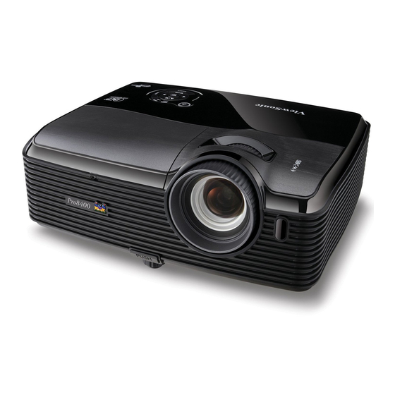
Page 5: Location Of Features, Controls, And I/O
9. Speaker 3. Elevator foot 10 .Focus ring 4. Lens cap strap 11.Zoom ring 5. Projection lens 12.Control panel 6. Front IR remote control sensor 13.Lamp cover 7. Ventilation holes (intake) Real View ViewSonic Corporation Pro8400 Confidential - Do Not Copy... - Page 6 1. Connection ports 2. AC power socket 3. Kensington lock 4. Rear IR remote control sensor 5. Speaker 6. Ventilation holes (exhaust) Bottom View 1. Ceiling mount (M4*8) 2. Tilt-adjustment feet 3. Security bar ViewSonic Corporation Pro8400 Confidential - Do Not Copy...
- Page 7 Enter to sub-menu and confirm the menu selecti on. 7. SOURCE Display the source selection bar . 8. MENU/EXIT Display or exit the on-screen display menus. Power Turn the projector on or off. Right/Panel key Activate panel key lock. ViewSonic Corporation Pro8400 Confidential - Do Not Copy...
- Page 8 For LAN display/ network control and web server . 8. HDMI 1 Connect HDMI output from video equipment to this jack. 9. HDMI 2 Connect HDMI output from video equipment to this jack . ViewSonic Corporation Pro8400 Confidential - Do Not Copy...
- Page 9 Connect composite video output from video equipment to this jack. 17. Computer in 2 Connect image input signal (analog RGB or component) to this jack. 18. Computer in 1 Connect image input signal (analo g RGB or component) to this jack. ViewSonic Corporation Pro8400 Confidential - Do Not Copy...
- Page 10 D. Remote Control ViewSonic Corporation Pro8400 Confidential - Do Not Copy...
- Page 11 ViewSonic Corporation Pro8400 Confidential - Do Not Copy...
-
Page 12: Pro8400 Lamp Specification
EN ISO 3744; measured in steady state lamp operation Switch-off lamp voltage 140V Cooling method forced air cooling at 1.5 m/s minimum Thermal Protection Tc1 switch point 95 ViewSonic Corporation Pro8400 Confidential - Do Not Copy... - Page 13 Do not modify the lamp and never use a lamp tha t has been modified. Any unusual shock or vibration to the lamp should be avoided during operation. Do not use any broken lamps. ViewSonic Corporation Pro8400 Confidential - Do Not Copy...
- Page 14 Use the lead below 200 C to prevent a deterioration of cladding clad of the fluorocarbon resin. The lead wire insulation clad shouldn ’t touch the reflector. Exchange the lamp that has already passed the life time immediately. ViewSonic Corporation Pro8400 Confidential - Do Not Copy...
-
Page 15: Pro8400 System Block Diagram
1.4 Pro8400 System Block Diagram ViewSonic Corporation Pro8400 Confidential - Do Not Copy... -
Page 16: Firmware (Pixelworks) Upgraded Flow
7) After finding the FW document, move highlight bar to ” Start Upgrade”. 8) Press right button to start upgrade procedure. 9) When complete the procedure, projector will turn off automatically. Unplug the power cord. ViewSonic Corporation Pro8400 Confidential - Do Not Copy... -
Page 17: Machine Disassembly And Replacement
3 Machine Disassembly and Replacement 3.1 Tools Item Photo Long Nose Nipper Hex Sleeves 5mm Screw Bit(+):107 Screw Bit(+):101 Screw Bit(+):102 Anti-static wrist strap Anti-static wrist gloves ViewSonic Corporation Pro8400 Confidential - Do Not Copy... -
Page 18: Disassembly Procedure
When you replace the projector lamp, never touch the new lamp with your bare hands. The invisible residue left by the oil on your hands may shorten the lamp life. Use lint-free gloves or finger cots are recommended. ViewSonic Corporation Pro8400 Confidential - Do Not Copy... - Page 19 1. Flip the projector on the table. J1635-A010-0A*8 2. Remove the screws J1635-A010-0A*8 on the Bottom cover as shown. Rotate the Focus Ring by forward sequence to take it off from the unit. ViewSonic Corporation Pro8400 Confidential - Do Not Copy...
- Page 20 Top Cover. 1. Remove four screws to lift up the keypad board. J1635-3720-0A *4 1. Remove all screws as shown P0P35-2500-00*8 J1635-A632-01*2 to remove the IO cover. J1635-C230-00*4 ViewSonic Corporation Pro8400 Confidential - Do Not Copy...
- Page 21 3. Remove two screws on the Main Board. 4. Remove the Main Board. 1. Remove three screws as shown. 2. Remove the three wires on the audio board. P2535-7300-0A*3 3. Remove the audio board. ViewSonic Corporation Pro8400 Confidential - Do Not Copy...
- Page 22 2. Remove the metal sheet of Ballast. J1635-D110-0A*2 Note Note: 2 wires have been connected to Ballast. Disconnect these 2 wires before remove the metal sheet. To Lamp To Power Board ViewSonic Corporation Pro8400 Confidential - Do Not Copy...
- Page 23 1. Loosen all screws of the two speakers and then remove them away. J1635-2045-00*4 2. Loosen the screws on the Power Board and then remove P2535-7300-0A*4 the Power module from Bottom Cover. J1635-D420-0A ViewSonic Corporation Pro8400 Confidential - Do Not Copy...
- Page 24 2. Remove the Fan. 3. Loosen the four screws on J1635-3660-0A *2 DMD Board. 4. Remove the heat sink and DMD Board. P2535-7300-0A *4 Loosen one screw to remove the metal sheet. P2535-7300-0A ViewSonic Corporation Pro8400 Confidential - Do Not Copy...
- Page 25 J1635-0780-0A *3 Loosen the two screws to remove the color wheel module gently. P5K35-0220-00 *2 1. Loosen the two screws on the Zoom Ring. 2. Remove the Zoom Ring. J1635-3188-00 *2 ViewSonic Corporation Pro8400 Confidential - Do Not Copy...
-
Page 26: Assembly Fan Module
Fan2 (J2394-0144-00 ): 1. Paste the Fan Pad (P4E38-1070-00) on the middle of it. 2. Paste the Fan Sponge*4 Fan Sponge*4 (P4G38-1180-00) on the top and bottom of it as picture shown. Fan Pad ViewSonic Corporation Pro8400 Confidential - Do Not Copy... -
Page 27: Disassembly Lamp Module
7. Replace the lamp cover and tighten the screw. 8. Turn on the projector. If the lamp does not turn on after the warm-up period, try reinstalling the lamp. 9. Reset the lamp hour. Refer to the “Information” menu. ViewSonic Corporation Pro8400 Confidential - Do Not Copy... -
Page 28: Troubleshooting And Verifying The Repair
“Equivalent Lamp Hours” item, press the direction key following the actions below: Right once, left twice, right once; then you will enter the Engineering Mode. ) Note: This FW version is just for reference. ViewSonic Corporation Pro8400 Confidential - Do Not Copy... - Page 29 Whatever main board, ballast, IR board, power board, lamp module or optical engine are all suitable to check by swapping modules. ViewSonic Corporation Pro8400 Confidential - Do Not Copy...
- Page 30 Safety Switch Replace keypad Replace Check LED and Check and FFC Main board keypad FFC Main board Check Check 7 pin Fuse Power output Replace Replace Replace fuse main board power board ViewSonic Corporation Pro8400 Confidential - Do Not Copy...
- Page 31 Audio board Replace Replace Check Check PWR 380V Power board Main board Main board output Replace Check Ballast Ballast Replace Check Main board Main board Replace Check CW Rotation while power CW module ViewSonic Corporation Pro8400 Confidential - Do Not Copy...
- Page 32 No Signal Turn on Turn on Check Check Source Source Source Source Replace Replace Check Check Cable Cable Cable Cable Replace Replace Check Check Main board Output signal Main board Main board ViewSonic Corporation Pro8400 Confidential - Do Not Copy...
- Page 33 Input signal Wheel Index Wheel Index setting Replace Replace Check Check Main board Main board Main board Main board Replace Replace Check Check Optical Engine Optical Engine Optical Engine Optical Engine ViewSonic Corporation Pro8400 Confidential - Do Not Copy...
- Page 34 Replace Keypad Check Check Battery and FFC Battery Level Keypad and FFC Replace Replace Check Check Remote Control Main board Remote Control Main board Replace Check Replace Check Main board Main board ViewSonic Corporation Pro8400 Confidential - Do Not Copy...
-
Page 35: Verifying The Repair
I/O port Video Standard Pattern generator (Ex. Quantum data) or DVD player Test Equipment Signal format NTSC I/O port S-Video Standard Pattern generator or DVD player Test Equipment 480i Signal format I/O port ViewSonic Corporation Pro8400 Confidential - Do Not Copy... - Page 36 2. Press Source button manually selects an input source Foot adjuster operation Foot adjuster. Test criteria Foot adjuster button Foot adjusters should stretch downward smoothly by pressing the foot adjuster buttons on the two sides ViewSonic Corporation Pro8400 Confidential - Do Not Copy...
- Page 37 Standard Pattern generator (Ex. Quantum data) Signal format 1920*1080 60Hz 60” in diagonal length Projected image size Test criteria Test Pattern ANSI Brightness Apparent color strip, bend and streak corner on the projected image are not allowable. ViewSonic Corporation Pro8400 Confidential - Do Not Copy...
- Page 38 5. Rotate Zoom ring to tele mode (Minimum projected image) 6. Adjust focus ring to make resolution of 4 corners and center are balanced. 7. Check the characters should be recognized easily. ViewSonic Corporation Pro8400 Confidential - Do Not Copy...
- Page 39 3. Adjust focus ring to make resolution of 4 corners and center are balanced. 4. Check the characters should be recognized easily. 5. Rotate Zoom ring to tele mode (Minimum projected image) ViewSonic Corporation Pro8400 Confidential - Do Not Copy...
- Page 40 Chroma automatic system (The alternative is CL -200) Test Equipment Test method Measure 9 points Criteria Marketing spec 20% off (8) Cosmetic standard for repaired projector Follow cosmetic standard for repair center. ViewSonic Corporation Pro8400 Confidential - Do Not Copy...
-
Page 41: Adjustment / Alignment Procedure
(4) Notice the changing of color till the RGB colors are distinguishable. NOTE: 1. The CW Index of each CW is not a ll the same. 2. Adjusting the CW Index till the R, G, B colors are distinguishable will be fine. ViewSonic Corporation Pro8400 Confidential - Do Not Copy... -
Page 42: Adc Calibration
(3) Press right button to execute ADC Calibration. C olor deviation is unacceptable. If the screen blinks once, and then back to search signal and at last search out the image of Gray16, this indicates the calibration is successful. ViewSonic Corporation Pro8400 Confidential - Do Not Copy... - Page 43 (6) Press right button to execute YPbPr Calibration. Color deviation is unacceptable. If the screen blinks once, and then back to search signal and at last search out the image of SMPTEbar, this indicates the calibration is successful. ViewSonic Corporation Pro8400 Confidential - Do Not Copy...
-
Page 44: Keystone Adjustment
(1) At horizontal platform, adjust the projector foot to make platform level. (2) And then enter the engineering mode, and then move down the color bar to “Keystone Cal.” item. (3) Press right button to adjust. ViewSonic Corporation Pro8400 Confidential - Do Not Copy... -
Page 45: Connector Information
This section provides each connector location on boards and function of each board. They will be useful for your detecting the defective boards. 6.1 Main Board Connector Description Connect to DMD Board 6.2 The backside of Main Board No10 No11 No12 No14 No13 ViewSonic Corporation Pro8400 Confidential - Do Not Copy... -
Page 46: Ballast Board
Safety switch No 13 Audio Board No 14 6.3 Ballast Board Connector Description No 1 Lamp power supply No 2 Ignite signal connected to Main board No 3 High Voltage Power supply ViewSonic Corporation Pro8400 Confidential - Do Not Copy... -
Page 47: Power Board
6.4 Power Board Connector Description No 1 380V output for ballast No 2 12V/5V output for Main board and Audio board ViewSonic Corporation Pro8400 Confidential - Do Not Copy... -
Page 48: Fru (Field Replaceable Unit) List
When working on the projec tor, use appropriate anti-static precautions such as anti -static mats, wrist straps and grounded work surfaces. Failure to do this can destroy static -sensitive components and make the product inoperable. ViewSonic Corporation Pro8400 Confidential - Do Not Copy... -
Page 49: Mechanical Drawing
14. Fan2 10. Left Speaker 9. Optical Engine 15. Right Speaker 12. F-IR Board 11. Fan1 13. Lens Frame 16. B-IR Board 17. Ballast 18. Power Board 19. Bottom Cover 20. Rear Foot ViewSonic Corporation Pro8400 Confidential - Do Not Copy... - Page 50 EXPLODED PARTS LIST (Pro8400) ViewSonic Model Number: VS13647 Rev:1a Item ViewSonic P/N Ref. P/N Description Q’ty P7U84-4520 Lamp Cover C-00010583 P7W84-4500 Top Cover C-00010758 P7U34-4620-00 Filter Cover C-00010588 P7W84-4530 IO Cover C-00010759 P7W84-7100 Main Board B-00010911 P7U34-4540-99 Lens Cover C-00010589...
-
Page 51: Packing Drawing
7.2 Packing drawing ViewSonic Corporation Pro8400 Confidential - Do Not Copy... - Page 52 ViewSonic Corporation Pro8400 Confidential - Do Not Copy...
- Page 53 PACKING PART LIST (Pro8400) ViewSonic Model Number: VS13647 Rev:1a Item ViewSonic P/N Ref. P/N Description Q'ty P7W38-5000-00 UL LB J4238-R815-01 SERIAL LB P2838-5001-00 WARNING LB P1638-5007-00 P1638-5010-00 P1238-R504-00 J4039-0082-00 BB BAG P7U39-7004-00 EPE P-00010782 P7U39-3000-00 POUCH P7W39-4000-00 QG DC-00010799 P7W39-A000-00 CD...
-
Page 54: Maintenance
If the filter cover is torn, replace it. 4. Replace the filter cover. 5. Attach the filter cover. 6. Plug the power back into the projector. ViewSonic Corporation Pro8400 Confidential - Do Not Copy... -
Page 55: Appendix A: Rs-232 Command And Configuration
Appendix A: RS-232 Command and Configuration Baud Rate: 19200 Parity Bit: none Data Bit: 8 Stop Bit: 1 Assign Port: COM1 ViewSonic Corporation Pro8400 Confidential - Do Not Copy... - Page 56 ViewSonic Corporation Pro8400 Confidential - Do Not Copy...
-
Page 57: Appendix B: Ir Control Code
Appendix B: IR Control Code ViewSonic Corporation Pro8400 Confidential - Do Not Copy... -
Page 58: Appendix C: How To Reset The Lamp Hours
(3) Move down the color bar to “ Equivalent Lamp Hours Reset” item. (4) Press “enter” button to enter sub-menu. (5) Press left button to select “yes” to reset Lamp Hours. (6)Then the Lamp Hours would reset to 0 hours. ViewSonic Corporation Pro8400 Confidential - Do Not Copy... -
Page 59: Recommended Spare Parts List
Above listed items are examples, supplier can expand the rows to add more necessary items. Remark 2: All revised RSPLs with newly added items or any change made should be highlighted and correlated with the ECN/ECR approved by ViewSonic Corporation. This is to eliminate repeated cross checks of Notice: 1. - Page 60 C. Do you have any other opinions or suggestions regarding this service manual? Reader’s basic dada: Name: Title: Company: Add: Tel: Fax: E-mail: After completing this form, please return it to ViewSonic Quality Assurance in the USA at facsimile 1-909-839-7943. ViewSonic Corporation Pro8400 Confidential - Do Not Copy...