Table of Contents
Advertisement
Quick Links
Operation, Parts
GX Electric Airless
Sprayers
For professional use only.
Not approved for use in explosive atmospheres or hazardous locations.
For portable airless spraying of architectural paints and coatings.
Models: GX
3000 psi (207 bar, 20.7 MPa) Maximum Working Pressure
See page 4 for additional model information.
Important Safety Instructions
Read all warnings and instructions in this manual, related manuals, and on the unit
including the power cord. Be familiar with the controls and the proper usage of the
equipment. Save these instructions.
Gun – 311861 (FTX) 312830 (SG3)
ti27285a
Use only genuine Graco replacement parts.
The use of non-Graco replacement parts may void warranty.
Related Manuals
Pump – 3A3172
3A3212C
graco.com/GX21op
EN
Advertisement
Table of Contents

Related Manuals for Graco GX series


Summary of Contents for Graco GX series
-
Page 1: Important Safety Instructions
Be familiar with the controls and the proper usage of the equipment. Save these instructions. Related Manuals Gun – 311861 (FTX) 312830 (SG3) Pump – 3A3172 ti27285a graco.com/GX21op Use only genuine Graco replacement parts. The use of non-Graco replacement parts may void warranty. -
Page 2: Table Of Contents
Contents Contents Models ............. . . 4 Warnings . - Page 3 Graco Standard Warranty ........
-
Page 4: Models
Models Models Model Stand DI Stand Hopper GX 19 17H211 GX 21 24Y680 FinishPro 17F924 GX 19 110474 Certified to CAN/CSA C22.2 No. 68 Conforms to UL 1450 GX 21 17H221 SA & Brazil ® Schuko GX 21 24Y680 CA & Brazil GX 21 17H218 230 Europe... -
Page 5: Warnings
Warnings Warnings The following warnings are for the setup, use, grounding, maintenance, and repair of this equipment. The exclamation point symbol alerts you to a general warning and the hazard symbols refer to procedure-specific risks. When these symbols appear in the body of this manual or on warning labels, refer back to these Warnings. -
Page 6: Fire And Explosion Hazard
Use Graco conductive or grounded high-pressure airless paint sprayer hoses. •... - Page 7 • Check hoses and parts for signs of damage. Replace any damaged hoses or parts. • This system is capable of producing 3000 psi. Use Graco replacement parts or accessories that are rated a minimum of 3000 psi. • Always engage the trigger lock when not spraying. Verify the trigger lock is functioning properly.
- Page 8 Warnings PRESSURIZED ALUMINUM PARTS HAZARD Use of fluids that are incompatible with aluminum in pressurized equipment can cause serious chemical reaction and equipment rupture. Failure to follow this warning can result in death, serious injury, or property damage. • Do not use 1,1,1-trichloroethane, methylene chloride, other halogenated hydrocarbon solvents or fluids containing such solvents.
-
Page 9: Know Your Sprayer
Know Your Sprayer Know Your Sprayer Stand Models ti27260a Pump Fluid Outlet Fitting (airless Prime / Spray Valve hose connection) PushPrime™ Button Airless Hose Pressure Control Knob InstaClean™ Fluid Filter (inside fluid ON/OFF Switch outlet) Suction Tube Inlet Strainer Drain Tube (with diffuser) Power Cord Airless Spray Gun Easy Access Door... -
Page 10: Di Stand Models
Know Your Sprayer DI Stand Models Pump Fluid Outlet Fitting (airless Prime / Spray Valve hose connection) PushPrime Button Airless Hose Pressure Control Knob InstaClean™ Fluid Filter (inside fluid ON/OFF Switch outlet) Suction Tube Inlet Strainer Drain Tube (with diffuser) Power Cord Airless Spray Gun Easy Access Door with Cover... -
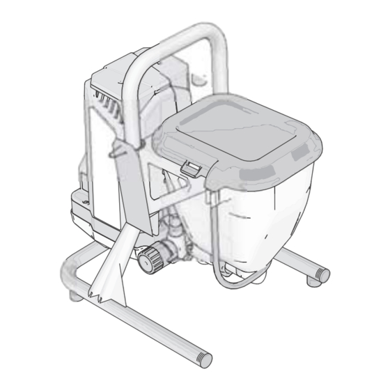
Page 11: Hopper Models
Know Your Sprayer Hopper Models ti27262a Airless Hose Prime / Spray Valve InstaClean™ Fluid Filter (inside fluid PushPrime Button outlet) Pressure Control Knob Inlet Strainer, inside hopper not ON/OFF Switch shown Hopper Power Cord Drain Tube (with diffuser) Easy Access Door Airless Spray Gun FTX Pump Removal Tool Reversible Spray Tip, Fine Finish... -
Page 12: Setup
Remove tip guard. Do not lose the seal. When unpacking sprayer for the first time or after long term storage perform setup procedure. Connect Graco airless hose to fluid outlet. Use wrench to tighten securely. ti25197a Turn Pressure Control Knob all the way left (counter-clockwise) to minimum pressure. -
Page 13: Start Up
Start Up Start Up Pressure Relief Procedure ti24931a Turn pressure control to lowest setting. Follow the Pressure Relief Procedure whenever you see this symbol. This equipment stays pressurized until pressure is manually relieved. To help prevent serious injury from pressurized ti27493a fluid, such as skin injection or splashed fluid, follow the Pressure Relief... -
Page 14: Flush Storage Fluid
Clear airless hose or spray tip obstruction. Prime/Spray Valve There are two types of Prime/Spray valves used on this group of Graco sprayers. The first type of Prime/Spray valve uses a knob that can be turned between the PRIME and SPRAY position. - Page 15 Start Up Place drain tube in waste pail. Submerge suction tube in a pail partially filled with water or flushing fluid. ti27268a Pour approximately two quarts (two liters) of water or flushing fluid into the hopper. Place Prime/Spray valve in PRIME position.
-
Page 16: Fill Pump
Start Up 10. Inspect for leaks. If leaks occur, per- Press PushPrime button twice to loosen inlet ball. form Pressure Relief Procedure, page 13, then tighten all fittings and repeat Start Up. If there are no leaks continue with the next step. Fill Pump Move suction tube to paint pail and submerge suction tube in paint. - Page 17 Start Up Release trigger. Engage trigger lock. Transfer drain tube to paint pail and clip to suction tube. On hopper models, clip drain tube to hopper. ti27139a NOTE: When motor stops sprayer is ready to paint. If motor continues to run sprayer is not properly primed, repeat Fill Pump and Fill Gun.
-
Page 18: How To Spray
How to Spray How to Spray Spray tip must be pushed all the way into the tip guard. Turn spray tip to push down. Spray Tip Installation To prevent spray tip leaks make certain spray ti27145a tip and tip guard are installed properly. Perform Pressure Relief Procedure, page 13. -
Page 19: Adjust Pressure Control
How to Spray Adjust Pressure Control The pressure control knob allows for infinite pressure adjustment. To reduce overspray, always start at the lowest pressure setting and increase pressure to the minimum setting that results in an acceptable spray pattern. 3000 psi 1500 psi 500 psi ti5597b... -
Page 20: Spray Techniques
How to Spray Spray Techniques Aiming Gun Use a piece of scrap cardboard to practice Aim center of spray of gun at bottom edge of these basic spraying techniques before you previous stroke, overlapping each stroke by begin spraying the surface. half. -
Page 21: Clear Tip Clog
How to Spray Clear Tip Clog In the event that particles or debris clog the spray tip, this sprayer is designed with a reversible spray tip that quickly and easily clears the particles without disassembling the sprayer. See Strain the Paint, page 12 for additional information. -
Page 22: Cleanup
Cleanup Cleanup Cleaning the sprayer after each use results in Separate drain tube (smaller) from suc- a trouble free start up the next time the tion tube (larger). sprayer is used. Cleaning from a Pail ti27405a (Stand Models Only) Place empty waste and flushing fluid Pail flushing only works with models that pails side by side. - Page 23 Cleanup Turn ON/OFF switch to ON position. 13. While continuing to trigger gun, quickly move gun to redirect spray into waste 10. Flush until approximately 1/3 of the pail. Continue triggering gun into waste flushing fluid is emptied from the pail. pail until flushing fluid dispensed from gun is relatively clear.
-
Page 24: Power Flush
Cleanup ti27153a Lift suction tube and drain tube from paint pail. Let paint drain into the pail. Place suction and drain tube in waste pail. Turn Pressure Control knob to the Prime/Clean setting. ti27232a 16. Turn ON/OFF switch to OFF position. 17. - Page 25 Cleanup Unscrew inlet strainer from suction tube. Place inlet strainer rinse in waste pail. ti27121a ti27158a 10. Connect garden hose to suction tube with Power Flush attachment valve. Leave drain tube in waste pail. ti27264a ti27 7155a Turn ON/OFF switch to ON position. Continue to hold gun trigger until 11.
-
Page 26: Hopper Flushing
Cleanup 19. Place Prime/Spray valve in PRIME Remove drain tube from paint hopper, position. wipe excess paint off outside. ti272 265a Place drain tube in waste pail. ti27232a 20. Turn ON/OFF switch to OFF position. Hopper Flushing (Hopper Models Only) ti27268a See Cleaning Fluid Compatibility, page 30. - Page 27 Cleanup Flush until approximately 1/3 of the flushing fluid is emptied from the hop- per. 10. Turn ON/OFF switch to OFF position. NOTE: Step 11 is for returning paint in hose to paint pail. One 50 ft (15 m) hose holds approximately 1 quart (1 liter) of paint.
-
Page 28: Cleaning Instaclean ™ Fluid Filter
Cleanup ™ Clean the Gun Cleaning InstaClean Fluid Filter Clean gun fluid filter with water or flushing fluid and a brush every time you (Optional) flush the system. Replace gun filter if damaged. The InstaClean Fluid Filter prevents particles from entering paint hose. After each use, remove and clean it to ensure peak performance. -
Page 29: Storage
Storage Storage With proper storage, the sprayer will be ready to use the next time it is needed. Always circulate Pump Armor storage fluid through system after cleaning. Water left in sprayer will corrode and damage pump. Follow Cleanup, page 22, or Power Flush, page 24. -
Page 30: Reference
Reference Reference Understanding Tip Number Spray Tip Selection The last three digits of tip number (i.e.: 221413) contain information about hole size and fan width on surface when gun is held 12 Selecting Tip Size in. (30.5 cm) from surface being sprayed. Spray tips come in a variety of hole sizes for First digit when doubled spraying a range of fluids. -
Page 31: Static Grounding Instructions
Reference • Do not place pail on a non-conductive surface To spray oil-based materials after such as paper or cardboard which interrupts spraying water-based materials, flush grounding continuity. the system thoroughly with mineral spir- its or a compatible oil-based flushing solvent first. -
Page 32: Quick Reference
Reference Quick Reference Page 9 Name Description • Prime/Spray valve In PRIME position directs fluid to drain tube. • In SPRAY position directs pressurized fluid to paint hose. • Automatically relieves system pressure in over- pressure situations. PushPrime button Taps the inlet ball when pushed to loosen it. Pressure control knob Increases (clockwise) and decreases (counter-clockwise) fluid pressure in pump, hose,... -
Page 33: Maintenance
• Purchase a pump repair kit and install according to instructions provided with kit, before your next job. ti27463a • See Pump Assembly, page 46 or con- sult a Graco/M authorized AGNUM retailer, distributor, or service center. 3A3212C... - Page 34 Maintenance Inlet Valve Removal Slide pump assembly off the mounting pins. An integrated tool is included in the frame to remove the inlet valve assembly from the pump. If you suspect that the inlet valve is clogged or stuck, remove the valve assembly and clean or replace.
- Page 35 Maintenance Pump Installation Swing easy access door pump door closed while pushing the entire door Slide pump assembly onto the mounting towards the inlet end of the pump. pins. ti27036a ti27478a Move pump displacement rod up or down until cap is level with the opening in the yoke.
-
Page 36: Troubleshooting
If not frozen, check for hardened paint in pump. If paint has hardened in pump. See page 33. If motor does not turn with pump removed, consult a Graco/ Magnum authorized retailer, distributor, or service center. Motor or control is damaged. - Page 37 Suction tube is leaking. Inspect suction tube connection for cracks or vacuum leaks. Outlet valve check ball is stuck. Unscrew outlet valve, remove, and clean assembly. Prime/Spray Valve is worn or Take sprayer to Graco/MAGNUM obstructed with debris. authorized service center. 3A3212C...
- Page 38 Troubleshooting Problem Cause Solution Pump is primed, but can not achieve Spray tip may be partially clogged. Clear spray tip clog. See page 21. good spray pattern. Reversible spray tip is in UNCLOG Rotate arrow-shaped handle on spray position. tip so it points forward to SPRAY position.
- Page 39 Choose spray tip with narrower fan. Make sure gun is close enough to surface. Fan pattern varies dramatically while Pressure control switch is worn and Take sprayer to Graco/M AGNUM spraying. causing excessive pressure variation. authorized service center. Cannot trigger spray gun.
-
Page 40: 17H211, 17H214 Stand Sprayers
17H211, 17H214 Stand Sprayers 17H211, 17H214 Stand Sprayers Ref. Torque 140-160 in-lb (16 - 18 N•m) 30-35 in-lb (3.5 - 4.0 N•m) 110-120 in-lb (12 - 14 N•m) See page 46. ti27270a 3A3212C... -
Page 41: 17H211, 17H214 Stand Sprayers Parts List
17H211, 17H214 Stand Sprayers 17H211, 17H214 Stand Sprayers Parts List Part Description Ref. Qty. Part Description Ref. Qty. 17J025 LABEL, front KIT, motor includes 1a HOSE, cpld, 1/4 in. x 17F756 120V, Model 17H211 50 ft 17F758 230V, Model 17H214 240794 Model 17H211 KIT, fan... -
Page 42: 24Y680, 17G183, 17H218, 17H219, 17H221 Di Stand Sprayers
24Y680, 17G183, 17H218, 17H219, 17H221 24Y680, 17G183, 17H218, 17H219, 17H221 DI Stand Sprayers Ref. Torque 30-35 in-lb (3.5 - 4.0 N•m) 110-120 in-lb (12 - 14 N•m) See page 46. ti27281a 3A3212C... -
Page 43: 24Y680, 17G183, 17H218, 17H219, 17H221 Di Stand Sprayers Parts List
24Y680, 17G183, 17H218, 17H219, 17H221 24Y680, 17G183, 17H218, 17H219, 17H221 DI Stand Sprayers Parts List Ref. Part Description Qty. Ref. Part Description Qty. 24b 116295 CLAMP, tube KIT, motor includes 1a 24c 195400 CLIP, tube 17K684 120V, Model 24Y680 24d 115489 CLAMP, drain tube 17L083 230V, Models 17G183, 24e 115099 WASHER, hose 17H218, 17H219, 17H221... -
Page 44: 17F924, 17G184, 17H222, 17H223 Hopper Sprayers
17F924, 17G184, 17H222, 17H223 Hopper 17F924, 17G184, 17H222, 17H223 Hopper Sprayers Ref. Torque 15-20 in-lb (1.5 - 2 N•m) 30-35 in-lb (3.5 - 4.0 N•m) 110-120 in-lb (12 - 14 N•m) See page 46. ti27282a 3A3212C... -
Page 45: 17F924, 17G184, 17H222, 17H223 Hopper Sprayers Parts List
17F924, 17G184, 17H222, 17H223 Hopper 17F924, 17G184, 17H222, 17H223 Hopper Sprayers Parts List Part Description Ref. Qty. Part Description Ref. Qty. 214698 HOSE, cpld, 3/16 in. x KIT, motor includes 1a 25ft 17F757 120V, Model 17F924 17F758 230V, Models 17G184, 17J261 GUN, spray, FTX 17H222, 17H223... -
Page 46: Pump Assembly
Pump Assembly Pump Assembly Ref. Torque Ref. Torque 140-160 in-lb (16 - 18 N•m) 220-250 in-lb (25 - 28 N•m) 270-330 in-lb (30 - 37 N•m) 320-380 in-lb (36 - 43 N•m) 30-35 ft-lb (40 - 48 N•m) 28a 28b ti27488a 3A3212C... -
Page 47: Pump Parts List
Pump Assembly Pump Parts List Part Description Ref. Qty. Part Description Ref. Qty. 288747 KIT, filter (Not installed 17G447 HOUSING, pump on all models.) 17D364 GUIDE, ball 120776 PACKING, O-ring 128336 SPRING, compression 24Y327 KIT, repair outlet 105445 BALL, 0.5 in. includes 12, 13 117501 SCREW, mach, slot... -
Page 48: Wiring Diagrams
Wiring Diagrams Wiring Diagrams 110/120V ti27233a 3A3212C... -
Page 49: 230V
Wiring Diagrams 230V ti27485a 3A3212C... -
Page 50: Technical Specifications
Technical Specifications Technical Specifications GX 19, GX 21, FinishPro GX 19 GX 19, GX 21, FinishPro GX 19 Metric Sprayer Maximum fluid working pressure 3000 psi 207 bar, 20.7 MPa Maximum Delivery GX 19/FinishPro GX 19 0.38 gpm 1.4 lpm GX 21 0.47 gpm 1.8 lpm... - Page 51 Technical Specifications GX 19, GX 21, FinishPro GX 19 Metric Noise** Sound pressure 83 dBa* Sound power 93 dBa* Materials of Construction Wetted materials on all models stainless steel, brass, leather, ultra-high molecular weight polyethylene (UHMWPE), carbide, nylon, aluminum, PVC, polypropylene, fluoroelastomer Notes * Startup pressures and displacement per cycle may vary based on suction condition,...
-
Page 52: Gx Ff
Technical Specifications GX FF GX FF Metric Sprayer Maximum fluid working pressure 3000 psi 207 bar, 20.7 MPa Maximum Delivery 0.38 gpm 1.4 lpm Maximum Tip Size 0.019 in. 0.048 mm Fluid Outlet npsm 1/4 in. 1/4 in. Generator Minimum 1500 W 110–120V, 8 A / 220–240V, 5 A, 1Ø... -
Page 53: Graco Standard Warranty
Graco’s written recommendations. This warranty does not cover, and Graco shall not be liable for general wear and tear, or any malfunction, damage or wear caused by faulty installation, misapplication, abrasion, corrosion, inadequate or improper maintenance, negligence, accident, tampering, or substitution of non-Graco component parts. -
Page 54: Graco Information
For the latest information about Graco products, visit www.graco.com. For patent information, see www.graco.com/patents. TO PLACE AN ORDER, contact your Graco distributor or call 1-800-690-2894 to identify the nearest distributor. All written and visual data contained in this document reflects the latest product information available at the time of publication.