Table of Contents
Advertisement
Quick Links
Form No. 3361-958 Rev B
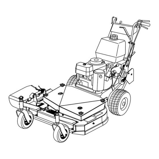
Commercial Walk-Behind Mower
Fixed Deck, Pistol Grip, Gear-Drive, with
32in Cutting Unit or 36in TURBO FORCE
®
Cutting Unit
Model No. 38682—Serial No. 290000001 and Up
Model No. 38684—Serial No. 290000001 and Up
To register your product or download an Operator's Manual or Parts Catalog at no charge, go to www.Toro.com.
Original Instructions (EN)
Advertisement
Table of Contents

Related Manuals for Toro 38682


Summary of Contents for Toro 38682
-
Page 1: Cutting Unit
32in Cutting Unit or 36in TURBO FORCE ® Cutting Unit Model No. 38682—Serial No. 290000001 and Up Model No. 38684—Serial No. 290000001 and Up To register your product or download an Operator's Manual or Parts Catalog at no charge, go to www.Toro.com. Original Instructions (EN) -
Page 2: Table Of Contents
Whenever you need service, genuine Toro parts, or additional information, contact an Authorized Service Introduction..............2 Dealer or Toro Customer Service and have the model Safety ................3 and serial numbers of your product ready. Figure 1 Safe Operating Practices ........3 identifies the location of the model and serial numbers Toro Mower Safety .......... -
Page 3: Safety
Safety Operating the Blade Control (PTO) Lever.............. 13 The Safety Interlock System........ 14 Note: The addition of attachments made by Driving Forward or Backward......14 other manufacturers that do not meet American Stopping the Mower ........... 15 National Standards Institute certification will cause Transporting Machines........ -
Page 4: Toro Mower Safety
• Look behind and down before backing up to be sure The following list contains safety information specific of a clear path. to Toro products and other safety information you must know. • Keep pets and bystanders away. • Slow down and use caution when making turns and This product is capable of amputating hands and crossing roads and sidewalks. -
Page 5: General Operation
• Do not touch equipment or attachment parts which may be hot from operation. Allow to cool before attempting to maintain, adjust or service. • Use only Toro-approved attachments. Warranty may be voided if used with unapproved attachments. • Check carefully for overhead clearances (i.e. -
Page 6: Slope Chart
Slope Chart... -
Page 7: Safety And Instructional Decals
Safety and Instructional Decals Safety decals and instructions are easily visible to the operator and are located near any area of potential danger. Replace any decal that is damaged or lost. 43-8480 95-5537 1. Read the Operator’s 3. Pull back to disengage Manual for instructions on operating the cutting blade 2. - Page 8 98-5130 1. Warning—read the Operator’s Manual for instructions on torquing the blade bolt/nut to 75-80 ft-lb (102-106 N⋅m). 106-2733 98-5954 1. Fast 3. Slow 2. Continuous variable setting 104-8569 105-4104 1. Reverse 3. Transmission speeds 2. Neutral 105-4111 106-0699...
-
Page 9: Product Overview
106-2737 1. Park 3. Neutral 5. Engine—run 2. Drive 4. Engine—stop 6. Warning—wear ear protection. Product Overview Figure 4 1. Throttle control 6. Drive lever 2. Ignition switch 7. Gear shift lever 3. Neutral/parking brake lock 8. Choke Figure 3 4. -
Page 10: Specifications
Contact your Neutral/Parking Brake Lock Authorized Service Dealer or Distributor or go to www.Toro.com for a list of all approved attachments Squeeze drive levers and move the locks rearward for and accessories. neutral lock. Squeeze drive levers and move the locks forward to set the parking brake. -
Page 11: Operation
Operation In certain conditions during fueling, static Adding Fuel electricity can be released causing a spark which can ignite the gasoline vapors. A fire Use Unleaded Regular Gasoline suitable for or explosion from gasoline can burn you and automotive use (85 pump octane minimum). Leaded others and can damage property. -
Page 12: Think Safety First
Important: Do not use fuel additives containing methanol or ethanol. Children or bystanders may be injured if they Add the correct amount of gas move or attempt to operate the machine while stabilizer/conditioner to the gas. it is unattended. Note: A fuel stabilizer/conditioner is most effective when mixed with fresh gasoline. -
Page 13: Starting And Stopping The Engine
Releasing the Neutral Locks 4. Disconnect the wire from the spark plug to prevent someone from accidentally starting the machine 1. Squeeze the drive levers back. while transporting or storing it. 2. Place your thumbs on the upper part of the locks 5. -
Page 14: The Safety Interlock System
• The machine is shifted into gear without holding the OPC levers. • The blade control (PTO) lever is engaged without holding the OPC levers. Testing the Safety Interlock System Test the safety interlock system before you use the machine each time. If the safety system does not operate as described, have an Authorized Service Dealer repair the safety system immediately. -
Page 15: Stopping The Mower
Driving Backward Side Discharging or Mulching the Grass 1. Ensure that the parking brakes are engaged. 2. Squeeze the OPC levers against the handles. This mower has a hinged grass deflector that disperses clippings to the side and down toward the turf. 3. -
Page 16: Adjusting The Height-Of-Cut
2. Stop the engine and wait for all moving parts to stop before leaving the operating position. 3. Hold the blade bolt and remove the nut (Figure 10). Figure 9 1. Position A 4. Drive spring 2. Position B 5. Adjustment bolt ( In position A) 6. -
Page 17: Adjusting The Handle Height
Figure 11 1. Axle pivot bolt 2. Axle adjustment bolt Figure 12 4. Place a jack under the rear center of the engine 1. Latch pin 3. Spacer, 1/2 inch (13 mm) frame. Raise the back end of the engine frame up 2. - Page 18 3. Remove the lower bolts (3/8 x 1 inch) and flange nuts securing handle to rear frame (Figure 14). 4. Pivot the handle to the desired operating position and install the lower flange bolts (3/8 x 1 inch)and flange nuts into the mounting holes. Tighten all flange bolts.
-
Page 19: Height Of Cut Chart
Height of Cut Chart Number of spacers Number of 1/4 inch blade spacers below spindle below caster 1/2 inch 3/16 inch (5 (13mm) Axle Position 1 inch (26 1–1/4 inch 1–1/2 inch 1–3/4 inch 2 inch (51 (32 mm) (38 mm) (45 mm) 1–1/8 inch 1–3/8 inch... -
Page 20: Maintenance
Maintenance Note: Determine the left and right sides of the machine from the normal operating position. Recommended Maintenance Schedule(s) Maintenance Service Maintenance Procedure Interval • Change the engine oil. After the first 8 hours • Check the mower belt tension. •... -
Page 21: Lubricating The Caster And Wheel Bearings
Note: Remove the mower deck cover to access the 3. Clean the grease fittings with a rag. Make sure to scrape any paint off the front of the fitting(s). grease fitting for the mower belt idler arm. 4. Connect a grease gun to the fitting. Pump grease into the fittings until grease begins to ooze out of the bearings. -
Page 22: Engine Maintenance
Engine Maintenance Servicing the Air Cleaner Service Interval/Specification Foam element: Clean it after every 25 operating hours. Paper element: Check it after every 50 operating hours. Replace it after every 200 operating hours or yearly, which ever comes first. Inspect the foam and paper elements and replace them if they are damaged or excessively dirty. -
Page 23: Servicing The Engine Oil
2. Place the air cleaner assembly onto the air cleaner base and secure it with the 2 wing nuts (Figure 18). 3. Place the air cleaner cover into position and tighten the cover knob (Figure 18). Servicing the Engine Oil Service Interval/Specification Figure 20 Change the engine oil as follows:... -
Page 24: Servicing The Spark Plugs
3. Apply a thin coat of new oil to the rubber gasket on the replacement filter (Figure 22). 4. Install the replacement oil filter to the filter adapter, turn the oil filter clockwise until the rubber gasket contacts the filter adapter, then tighten the filter an additional 3/4 turn (Figure 22). -
Page 25: Fuel System Maintenance
Fuel System 4. Clean around the spark plugs to prevent dirt from falling into the engine and potentially causing Maintenance damage. 5. Remove the spark plugs and the metal washers. Draining the Fuel Tank Checking the Spark Plugs 1. Look at the center of the spark plugs (Figure 24). If you see light brown or gray on the insulator, the In certain conditions, gasoline is extremely engine is operating properly. -
Page 26: Replacing The Fuel Filter
Figure 25 1. Fuel shut-off valve 2. Fuel filter Figure 26 6. Wipe up any spilled fuel. 1. Hose clamp 3. Filter 2. Fuel line Replacing the Fuel Filter 5. Remove the filter from the fuel lines. Replace the fuel filter after every 200 operating hours or 6. -
Page 27: Drive System Maintenance
Drive System Cooling System Maintenance Maintenance Cleaning the Air Intake Screen Checking the Tire Pressure Before each use remove any build-up of grass, dirt Check the pressure at the valve stem after every or other debris from the cylinder and cylinder head 50 operating hours or monthly, whichever occurs first cooling fins, air intake screen on flywheel end, and (Figure 27). -
Page 28: Brake Maintenance
Brake Maintenance 4. Position the wing nuts so that the brakes engage when you squeeze the drive levers enough to place the neutral/parking brake locks forward, and then Servicing the Brakes set the brakes. Before each use, check brakes on both a level surface 5. -
Page 29: Belt Maintenance
Belt Maintenance Checking the Belts Check all belts after every 50 operating hours or monthly, whichever occurs first. Look for dirt, wear, cracks and signs of overheating. Replacing the Traction Drive Belt Figure 31 1. Remove hairpin cotter securing brake rod to brake 1. -
Page 30: Adjusting The Mower Belt Tension
Note: The proper mower belt tension is 10-15 lbf. Note: If the assist arm does not contact the front (44-67 N) with the belt deflected 1/2 inch (13 mm) stop on the mower deck (Figure 34), adjust the clevis halfway between the pulleys (Figure 32). to bring the bell crank closer to the transmission output shaft (Figure 33). -
Page 31: Controls System Maintenance
Controls System 1. Disengage the blade control (PTO) lever and set the parking brakes. Maintenance 2. Stop the engine and wait for all moving parts to stop before leaving the operating position. Adjusting the Control Rods 3. Loosen the locknut on the turnbuckle (Figure 34). 1. -
Page 32: Mower Deck Maintenance
Mower Deck 3. Install the control rod to the drive lever and the neutral/parking brake lock. Secure the control rod Maintenance with a clevis pin and a hairpin cotter (Figure 36). 4. Check the operation of the control rod. If you need to adjust it, remove the hairpin cotter and the clevis Servicing the Cutting Blades pin that secure the control rod to the drive levers. -
Page 33: Removing The Blades
Replace the blades if you hit a solid object or if the blades are out of balance or bent. To ensure optimum performance and continued safety conformance of the machine, use genuine Toro replacement blades. Replacement blades made by other manufacturers may result in non-conformance with safety standards. -
Page 34: Adjusting The Blade Brake
Figure 42 1. Blade 2. Balancer Installing the Blades 1. Place the blade onto the bolt and over the curved washer. Select the proper number of spacer(s) for the height-of- cut, and slide the bolt into the spindle (Figure 40). Important: The curved part of the blade must point upward toward the inside of the mower to ensure proper cutting. -
Page 35: Replacing The Grass Deflector
Figure 43 1. Spring mounting bolts 3. 1/8-3/16 inch (3mm-5mm) 2. Blade brake pad Figure 44 Replacing the Grass Deflector 1. Bolt 5. Spring installed 2. Spacer 6. Grass Deflector 3. Locknut 7. L end of spring, place behind deck edge before installing bolt 4. -
Page 36: Storage
Storage 11. Paint all scratched or bare metal surfaces. Paint is available from your Authorized Service Dealer. Cleaning and Storage 12. Store the machine in a clean, dry garage or storage area. Remove the key from the ignition switch and 1. -
Page 37: Troubleshooting
Troubleshooting Problem Possible Cause Corrective Action Engine will not start, starts hard, or fails 1. Fuel tank is empty. 1. Fill the fuel tank with gasoline. to keep running. 2. Fuel shut off valve is closed. 2. Open the fuel shut off valve. 3. - Page 38 Problem Possible Cause Corrective Action Blades do not rotate. 1. Mower deck belt is worn or loose. 1. Check the belt tension. 2. Mower deck belt is broken. 2. Install a new deck belt. 3. Mower deck belt is off pulley. 3.
-
Page 39: Schematics
Schematics Electrical Schematic (Rev. A) -
Page 40: The Toro Total Coverage Guarantee
Countries Other than the United States or Canada Customers who have purchased Toro products outside the United States or Canada should contact their Toro Distributor (Dealer) to obtain guarantee policies for your country, province, or state. If for any reason you are dissatisfi ed with your Distributor’s service or have diffi culty obtaining guarantee information, contact the Toro importer.