Table of Contents
Advertisement
Available languages
Available languages
Quick Links
Advertisement
Chapters
Table of Contents

Related Manuals for Fagor HAN 8000


Summary of Contents for Fagor HAN 8000
- Page 1 HAN 8000 4 x HDMI to ASI / IP Encoder...
- Page 2 TABLE OF CONTENTS...
-
Page 3: Table Of Contents
Contenido SAFETY INSTRUCTION ..........................1 OVERVIEW............................... 2 SYSTEM PRINCIPLE ..........................3 SYSTEM DIAGRAM ..........................3 3.1.1 HDMI ............................4 3.1.2 A V Encoding..........................4 3.1.3 TS Process............................ 4 3.1.4 Data output port .......................... 4 SPECIFICATIONS............................5 HDMI..............................5 H.264 Video Compression ........................ - Page 4 BASIC PROGRAMMING GUIDE........................10 KEYBOARD + LCD..........................10 7.1.1 Lock Status display ........................10 7.1.2 Main menu display ........................10 7.1.3 Encoder Setting..........................10 7.1.4 Programming of the rest of encoders..................14 7.1.5 ASI ..............................14 7.1.6 Output Setting ..........................14 7.1.7 IP Output ............................15 7.1.8 Network Setting ..........................19 7.1.9...
-
Page 5: Safety Instruction
SAFETY INSTRUCTION Read this manual carefully before use. Do not open the case without disconnecting it from the mains Allows the air circulation around the equipment Protects against the water or liquids drops on the equipment ... -
Page 6: Overview
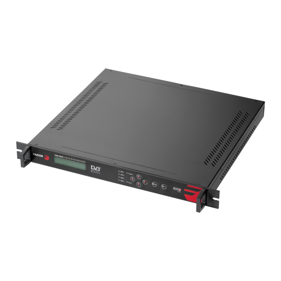
OVERVIEW. The HAN 8000 encoder modulates the content of 4 HDMI input (MPEG-4 AVC/H.264 HD) signals to a DVB-ASI or IP output. It supports 1080i/p and 720p. The housing of this equipment is adapted to the 19” rack with 1 unit height. -
Page 7: System Principle
SYSTEM PRINCIPLE 3.1 SYSTEM DIAGRAM HD A/D HDMI in 1 Encoding HD A/D HDMI in 2 Encoding ASI Output HD A/D HDMI in 3 Encoding IP/UDP out HD A/D HDMI in 3 Encoding ASI input... -
Page 8: Hdmi
3.1.1 HDMI As it is showed in the above diagram the HDMI input signals are sent to the encoding module. 3.1.2 A V Encoding Video coding adopts H.264 real time compression encode chip to encode the digitalized video data from video port and then output video ES (Elementary Stream) which will be sent to video packetizer. And the PES (Packetized Elementary Stream) generates and it will do audio and video stream processing. -
Page 9: Specifications
SPECIFICATIONS 4×HDMI High Definition Multimedia Interface Input DVB standard, BNC interface 4:2:0 encoding H.264 HP@L4 MP@L3 H.264 Adaptive Field Frame (AFF) Video Coding H.264 Field-Based (FB) full HD: 1920×1080×60/50i/p, 1280×720×60p/50p Standard ISO/IEC14496-10 (H.264/MPEG-4 AVC) Bit rate 128, 160, 192, 224, 256, 320, 384Kbps Audio Property MPEG-1 Layer2... -
Page 10: Audio
4.2.2 Audio MPEG-1 Layer 1/2 4.2.3 Format. DVB Transport Stream. 4.3 DATA PORT. DVB ASI; IEEE802.3 Ethernet, RJ45 4.3.1 DVB ASI Standard: DVB ASI Connectors: BNC Impedance: 75 Ohm Package format: 188 bytes 4.4 CONNECTIONS 4.4.1 Input 4 x HDMI inputs, and one ASI input. 4.4.2 Video Format High definition: 1920*1080i/p *50/60;... -
Page 11: Equipment Connection
EQUIPMENT CONNECTION. 5.1 FRONT PANEL DISPLAY AND KEY BUTTON 1: LCD 2: ASI active input indicator LED. 3: HDMI input active indicator LED. 4: Error indicator LED. 5: Power indicator LED. 6: Keyboard. LEFT, RIGHT: move the cursor / UP, DOWN: change parameters. ... -
Page 12: Installation Guide
INSTALLATION GUIDE. 6.1 INSTALLATION PREPARATION. Before installation check possible lose or damage of the device during transportation and read the complete user manual. Prepare a suitable environment for installation Install the device. Connect the signal cables. 6.2 ENVIRONMENT ENQUIRIES. -
Page 13: Rack Grounding
6.3.1 Rack grounding. Ground terminals of racks in one room should be separately connected to protective are copper bar provided by side board. And ground wire should be as far as possible short. If the wire is too long when installing, please cut off to avoid ground wire coiling. -
Page 14: Basic Programming Guide
BASIC PROGRAMMING GUIDE. 7.1 KEYBOARD + LCD. 7.1.1 Lock Status display 4IN1 HD HDMI Encoder PG: 04 Bitrate: 30.000Mbps 7.1.2 Main menu display After initialization, the menu shows as below (Press ‘up or down’ key to choose menu, then press the ‘enter’... - Page 15 1.1. Video Format 1.2. System BitRate 1.3. CBR-VBR 1.4. Video Profile 1.5. Video Level 1.6. Audio BitRate 1.7. PMT PID 1.8. VIDEO PID 1.9. AUDIO PID 1.10. PCR PID 1.11. Prog. Name 1.12. Provider Video Format 7.1.3.1 1.1. Video Format AUTO 1920*1080*60p 1920*1080*59.94p...
- Page 16 CBR-VBR 7.1.3.3 We can choose between constant (CBR) and variable (VBR) Bit Rates: 1.3. CBR-VBR Video Profile 7.1.3.4 1.4. Video Profile High Profile Main Profile Baseline Profile Auto-defect Video Level 7.1.3.5 1.5. Video Level Level 4 Level 4.1 Level 4.2 Level 1.2 Level 1.3 Level 2...
- Page 17 PMT PID 7.1.3.7 1.7. PMT PID 0256 VIDEO PID 7.1.3.8 1.8. VIDEO PID 0257 AUDIO PID 7.1.3.9 1.9. AUDIO PID 0258 PCR PID 7.1.3.10 1.10. PCR PID 0259 Prog. Name 7.1.3.11 1.11. Prog. Name HD Encoder 1 Provider 7.1.3.12 1.12. Provider...
-
Page 18: Programming Of The Rest Of Encoders
Prog. Number 7.1.3.13 1.13. Prog. Number 0256 Volume Set 7.1.3.14 1.14. Volume Set 7.1.4 Programming of the rest of encoders. To configure the rest of encoders proceed as it is described above. 7.1.5 ASI It shows the list of programs that arrives from the ASI input: Program Total oo List Empty 7.1.6 Output Setting... -
Page 19: Ip Output
TS ID 7.1.6.2 6.2. TS ID 00000 OR. NET. ID. 7.1.6.3 6.3. OR. NET. ID 00000 7.1.7 IP Output 7.1. Encoder 1 7.2. Encoder 2 7.3. Encoder 3 7.4. Encoder 4 7.5. Subnet Mask 7.6. Gateway 7.7. Local IP 7.8. Local MAC Encoder 1 7.1.7.1 7.1.1. - Page 20 7.1.7.1.2 Destination IP 7.1.2. Destination IP 224.002.002.001 7.1.7.1.3 Destination PO 7.1.3. Destination PO 10001 Encoder 2 7.1.7.2 7.2.1. Enable 7.2.2. Destination IP 7.2.3. Destination PO 7.1.7.2.1 Enable 7.2.1. Enable 7.1.7.2.2 Destination IP 7.2.2. Destination IP 224.002.002.002 7.1.7.2.3 Destination PO 7.2.3. Destination PO 10002...
- Page 21 Encoder 3 7.1.7.3 7.3.1. Enable 7.3.2. Destination IP 7.3.3. Destination PO 7.1.7.3.1 Enable 7.3.1. Enable 7.1.7.3.2 Destination IP 7.3.2. Destination IP 224.002.002.003 7.1.7.3.3 Destination PO 7.3.3. Destination PO 10003 Encoder 4 7.1.7.4 7.4.1. Enable 7.4.2. Destination IP 7.4.3. Destination PO 7.1.7.4.1 Enable 7.4.1.
- Page 22 7.1.7.4.2 Destination IP 7.4.2. Destination IP 224.002.002.004 7.1.7.4.3 Destination PO 7.4.3. Destination PO 10004 Subnet Mask 7.1.7.5 7.5. Subnet Mask 255.255.255.000 Gateway 7.1.7.6 7.6. Gateway 192.168.000.001 Local IP 7.1.7.7 7.7. Local IP 192.168.000.190 Local MAC 7.1.7.8 7.8. Local MAC 00:07:0E:15:1C:23 Local Port 7.1.7.9 7.9.
-
Page 23: Network Setting
7.1.8 Network Setting 8.1. IP Address 8.2. Subnet Mask 8.3. Gateway 8.4. NMS UDP Port IP Address 7.1.8.1 8.1. IP Address 192.168.000.218 Subnet Mask 7.1.8.2 8.2. Subnet Mask 255.255.255.000 Gateway 7.1.8.3 8.3. Gateway 192.168.000.001 NMS UDP Port 7.1.8.4 8.4. NMS UDP Port 2009 MAC Address 7.1.8.5... -
Page 24: Save Config
7.1.9 Save Config 9. Save Config Please Wait… Power Failure Saving: When power failure, it can automatically save last status and start again when power on. 7.1.10 Load Config 10.1. Reload Config 10.2. Restore Config Reload Config 7.1.10.1 10.1. Reload Config Please Wait…... -
Page 25: Error Info
The system works normally after all above settings. 7.1.13 Error Info. 13. Error Info. List Empty 7.1.14 Error Info and Shooting 7.1.15 Indication Status There are 2 LED indicators on the panel: 1. “POWER” is power indicator. When switch on, it’s green, which indicates device works well. -
Page 26: Nms Operation Guide
NMS OPERATION GUIDE Network Management System (NMS) can remotely set configuration and monitor the device. It can be used only after being authorized. Except setting configuration by front panel, you can also use NMS on a PC to set and monitor device, with UDP protocol and supporting windows operation system. 8.1 NMS LOGIN NMS Login Interface Default user name and password are “admin”. - Page 27 Current NMS is without any device, user can add per his device. I: Menu Bar IX: Restore Config II: Open Device X: Reload Config III: Save Device XI: Import Config IV: Add Freq Node XII: Export Config V: Add Device XIII: Device List VI: Edit Device XIV: Device Connection Info...
-
Page 28: Add Frequency
when opening or closing the network management software. 8.2 ADD FREQUENCY “Add Frequency”: all devices can be divided and managed by frequency. Click “Add Freq Node”, then a dialog for adding frequency shows up. Input a frequency, like 385MHZ”, and then click “OK”... -
Page 29: Edit Device
Add “HD H264 4IN1 Encoder” Choose device type “HD H264 4in1 Encoder”, set device name (you can name as you like), and set IP address and Port of the device. You can check IP address by clicking down key on the panel or you can enter into “Network Setting” in the menu to check it. Default IP address and Port for HD H264 4in1 Encoder are 192.168.000.218 and 2009. - Page 30 If configuration is wrong, please choose the device and then click “Edit Device”, then below dialog shows up. Modify it and then click “OK” to save. 2. Check if there is IP conflict. Turn off the device, and input “cmd.exe” at command column on your PC: After entering into it: Input “arp –d”...
- Page 31 Input “PING”: Here the ping is 192.168.0.20 (you can put your device IP address when you do it). Here we found 192.168.0.20 passed, which means there is already a device with 192.168.0.20. Then we can find the device out and modify the IP address of the device or your device. After shooting the problem, the icon turns...
-
Page 32: Check And Set Configuration
At the device list column, click device name to check it. Check the basic info (like firmware and software version) at the device connection column and edit it at the right device operation area. “Del Device”: delete the device you don’t need from the device list. 8.5 CHECK AND SET CONFIGURATION Note: user had better do the following operation before configuring the device: Click... -
Page 33: Output Setting
8.5.1 Output Setting “Get”: Read current configuration from the device. “Set”: Confirm configuration and enable it. -
Page 34: Audio And Video Config
8.5.2 Audio and Video Config “Get”: Read current configuration from the device. “Set”: Confirm configuration and enable it. -
Page 35: Asi
8.5.3 ASI... -
Page 36: Pid Passthrough
8.5.4 PID Passthrough... -
Page 37: Edit Nit
8.5.5 Edit NIT... -
Page 38: Ip Output
8.5.6 IP Output MPTS Output 8.5.6.1... -
Page 39: Public Function Of Nms
SPTS Output 8.5.6.2 “Destination IP Out Setting”: set destination IP address and port. After choosing “enable”, the data port begins sending IP data to destination. “Local IP Address”: set the source address of IP package and gateway information. 8.6 PUBLIC FUNCTION OF NMS Public function of NMS includes “Save Config”, “Restore Cong.”, “Reload Config”, “Import Config”, and “Export Config”. - Page 40 Choose a device at device list. “Save Config”: After committing or confirming set configuration, click this button to save all configuration into “FLASH” (storage); you do this by front panel. “Restore Cong.”: renew and start using the configuration. You can read the renewed configuration by clicking “refresh”...
- Page 41 configuration when it needs to renew the configuration or to use a back-up device in future.
- Page 44 HAN 8000 Encoder 4 entradas HDMI a salidas ASI / IP...
- Page 45 TABLE OF CONTENTS Contenido INSTRUCCIONES DE SEGURIDAD ......................1 INTRODUCCIÓN............................2 PRINCIPIOS DE FUNCIONAMIENTO ......................2 DIAGRAMA DEL SISTEMA ........................2 3.1.1 HDMI ............................3 3.1.2 Codificación A/V........................... 3 3.1.3 Procesado del TS .......................... 3 ESPECIFICACIONES........................... 4 HDMI..............................4 H.264 Compresión de Vídeo.
- Page 46 TECLADO + PANTALLA LCD........................8 7.1.1 Pantalla cuando está en estado de bloqueo.................. 8 7.1.2 Pantalla de menú principal ......................8 7.1.3 Configuración del Encoder......................8 7.1.4 Programación del resto de los encoders..................12 7.1.5 ASI ..............................12 7.1.6 Configuración de las salidas ......................12 7.1.7...
- Page 47 ...................................37...
- Page 48 HAN 8000 Encoder 4 entradas HDMI a salidas ASI / IP...
- Page 49 TABLE OF CONTENTS Contenido INSTRUCCIONES DE SEGURIDAD ......................1 INTRODUCCIÓN............................2 PRINCIPIOS DE FUNCIONAMIENTO ......................2 DIAGRAMA DEL SISTEMA ........................2 3.1.1 HDMI ............................3 3.1.2 Codificación A/V........................... 3 3.1.3 Procesado del TS .......................... 3 ESPECIFICACIONES........................... 4 HDMI..............................4 H.264 Compresión de Vídeo.
- Page 50 TECLADO + PANTALLA LCD........................8 7.1.1 Pantalla cuando está en estado de bloqueo.................. 8 7.1.2 Pantalla de menú principal ......................8 7.1.3 Configuración del Encoder......................8 7.1.4 Programación del resto de los encoders..................12 7.1.5 ASI ..............................12 7.1.6 Configuración de las salidas ......................12 7.1.7...
- Page 51 ...................................37...
-
Page 53: Instrucciones De Seguridad
INSTRUCCIONES DE SEGURIDAD Lea atentamente este manual antes del uso del equipo. No abra el equipo sin antes haber desconectado la alimentación de red. Dejar espacio alrededor del equipo para facilitar la ventilación del mismo. Evitar la humedad y el contacto con líquidos. ... -
Page 54: Introducción
INTRODUCCIÓN. El encoder HAN 8000 codifica las señales provenientes de hasta 4 entradas HDMI (MPEG-4 AVC/H.264 HD) en un stream ASI o una salida IP. Soporta resoluciones de hasta 1920i/p. La mecánica de este equipo se adapta a un rack de 19” teniendo una unidad de altura. -
Page 55: Hdmi
3.1.1 HDMI Como se muestra en el diagrama, las señales de las entradas HDMI se pasan al módulo de codificación. 3.1.2 Codificación A/V. El chip de codificación utiliza la comprensión de vídeo en tiempo real H.264 para tomar los datos de vídeo digital que le llegan desde el puerto de entrada entregando un Elementary Stream (ES) que se envía al empaquetador de vídeo. -
Page 56: Especificaciones
ESPECIFICACIONES 4×HDMI High Definition Multimedia Interface (Interfaz multimedia de alta definición) Entradas Estándar DVB, conector BNC 4:2:0 encoding H.264 HP@L4 MP@L3 H.264 Adaptive Field Frame (AFF) Codificación de Video H.264 Field-Based (FB) full HD: 1920×1080×60/50i/p, 1280×720×60p/50p Estándar ISO/IEC14496-10 (H.264/MPEG-4 AVC) Bit rate 128, 160, 192, 224, 256, 320, 384Kbps Audio... -
Page 57: Audio
4.2.2 Audio MPEG-1 Layer 1/2 4.2.3 Formato. DVB Transport Stream. 4.3 PUERTO DE DATOS. DVB ASI; IEEE802.3 Ethernet, RJ45 4.3.1 DVB ASI Estándar: DVB ASI Conectores: BNC Impedancia: 75 Ohm Formato de los paquetes: 188 bytes 4.4 CONEXIONES 4.4.1 Entradas 4 entradas HDMI, y una entrada ASI. -
Page 58: Descripción Física Del Equipo
DESCRIPCIÓN FÍSICA DEL EQUIPO. 5.1 PANEL FRONTAL: PANTALLA Y TECLADO DE MEMBRANA 1: Pantalla LCD 2: Indicador LED de que la entrada ASI está activada. 3: Indicador LED de que la entrada HDMI correspondiente está activa. 4: Indicador LED de error. ... -
Page 59: Guía De Instalación
GUÍA DE INSTALACIÓN. 6.1 PREPARACIÓN DE LA INSTALACIÓN. Antes de comenzar la instalación comprobar que el equipo no ha sufrido daños durante el transporte y lea este manual. Seleccione un lugar adecuado para su instalación. Instale el equipo. ... -
Page 60: Guía Básica De Programación
GUÍA BÁSICA DE PROGRAMACIÓN. 7.1 TECLADO + PANTALLA LCD. 7.1.1 Pantalla cuando está en estado de bloqueo. 4IN1 HD HDMI Encoder PG: 04 Bitrate: 30.000Mbps 7.1.2 Pantalla de menú principal Una vez desbloqueado la pantalla muestra el siguiente menú (pulse las teclas ‘arriba/abajo’ para seleccionar dentro del menú... - Page 61 1.1. Video Format 1.2. System BitRate 1.3. CBR-VBR 1.4. Video Profile 1.5. Video Level 1.6. Audio BitRate 1.7. PMT PID 1.8. VIDEO PID 1.9. AUDIO PID 1.10. PCR PID 1.11. Prog. Name 1.12. Provider Formato de Vídeo. 7.1.3.1 1.1. Video Format AUTO 1920*1080*60p 1920*1080*59.94p...
- Page 62 CBR-VBR 7.1.3.3 Tenemos la opción de seleccionar un bit-rate constante (CBR) o variable (VBR): 1.3. CBR-VBR Perfil de Video 7.1.3.4 1.4. Video Profile High Profile Main Profile Baseline Profile Auto-defect Nivel de Video 7.1.3.5 1.5. Video Level Level 4 Level 4.1 Level 4.2 Level 1.2 Level 1.3...
- Page 63 PMT PID 7.1.3.7 1.7. PMT PID 0256 VIDEO PID 7.1.3.8 1.8. VIDEO PID 0257 AUDIO PID 7.1.3.9 1.9. AUDIO PID 0258 PCR PID 7.1.3.10 1.10. PCR PID 0259 Prog. Name 7.1.3.11 1.11. Prog. Name HD Encoder 1 Provider 7.1.3.12 1.12. Provider...
-
Page 64: Programación Del Resto De Los Encoders
Prog. Number 7.1.3.13 1.13. Prog. Number 0256 Volume Set 7.1.3.14 1.14. Volume Set 7.1.4 Programación del resto de los encoders. La descripción precedente para el Encoder 1, sirve para el resto de los encoders. 7.1.5 ASI Muestra la lista de programas que llegan de la entrada ASI: Program Total oo List Empty 7.1.6 Configuración de las salidas... -
Page 65: Salida Ip
TS ID 7.1.6.2 6.2. TS ID 00000 OR. NET. ID. 7.1.6.3 6.3. OR. NET. ID 00000 7.1.7 Salida IP 7.1. Encoder 1 7.2. Encoder 2 7.3. Encoder 3 7.4. Encoder 4 7.5. Subnet Mask 7.6. Gateway 7.7. Local IP 7.8. Local MAC Encoder 1 7.1.7.1 7.1.1. - Page 66 7.1.7.1.2 Dirección de destino IP 7.1.2. Destination IP 224.002.002.001 7.1.7.1.3 Destino PO 7.1.3. Destination PO 10001 Encoder 2 7.1.7.2 7.2.1. Enable 7.2.2. Destination IP 7.2.3. Destination PO 7.1.7.2.1 Activación 7.2.1. Enable 7.1.7.2.2 Dirección IP 7.2.2. Destination IP 224.002.002.002 7.1.7.2.3 Dirección 7.1.7.2.4 7.2.3.
- Page 67 Encoder 3 7.1.7.3 7.3.1. Enable 7.3.2. Destination IP 7.3.3. Destination PO 7.1.7.3.1 Activación 7.3.1. Enable 7.1.7.3.2 Dirección IP 7.3.2. Destination IP 224.002.002.003 7.1.7.3.3 Dirección PO 7.3.3. Destination PO 10003 Encoder 4 7.1.7.4 7.4.1. Enable 7.4.2. Destination IP 7.4.3. Destination PO 7.1.7.4.1 Activación 7.4.1.
- Page 68 7.1.7.4.2 Dirección IP 7.4.2. Destination IP 224.002.002.004 7.1.7.4.3 Dirección PO 7.4.3. Destination PO 10004 Subnet Mask 7.1.7.5 7.5. Subnet Mask 255.255.255.000 Gateway 7.1.7.6 7.6. Gateway 192.168.000.001 Local IP 7.1.7.7 7.7. Local IP 192.168.000.190 Local MAC 7.1.7.8 7.8. Local MAC 00:07:0E:15:1C:23 Local Port 7.1.7.9 7.9.
-
Page 69: Configuración De Red
7.1.8 Configuración de red. 8.1. IP Address 8.2. Subnet Mask 8.3. Gateway 8.4. NMS UDP Port Dirección IP 7.1.8.1 8.1. IP Address 192.168.000.218 Subnet Mask 7.1.8.2 8.2. Subnet Mask 255.255.255.000 Gateway 7.1.8.3 8.3. Gateway 192.168.000.001 NMS UDP Port 7.1.8.4 8.4. NMS UDP Port 2009 MAC Address 7.1.8.5... -
Page 70: Guardar Configuración
7.1.9 Guardar configuración. 9. Save Config Please Wait… Power Failure Saving: En caso de fallo de alimentación del equipo el equipo memoriza la configuración que tienen en ese momento y la recupera en cuanto se recupera la alimentación. 7.1.10 Load Config 10.1. -
Page 71: Idioma
7.1.12 Idioma 12. Language English El sistema funcionará con normalidad una vez se hayan configurado todos estos ajustes. 7.1.13 Información de error. 13. Error Info. List Empty 7.1.14 Indicador de Status Hay dos LEDs de señalización en el panel frontal: There are 2 LED indicators on the panel: 1. -
Page 72: Guía De Funcionamiento Del Nms
GUÍA DE FUNCIONAMIENTO DEL NMS Network Management System (NMS), Sistema de gestión de la red permite configurar y monitorizar en remoto el equipo. Solo puede ser utilizado por un usuario autorizado. Except setting configuration by front panel, you can also use NMS on a PC to set and monitor device, with UDP protocol and supporting windows operation system. - Page 73 Estos son los diferentes elementos que aparecen en pantalla. I: Barra de menú IX: Restaurar Configuración II: Abrir un dispositivo X: Recargar Configuración III: Guardar Dispositivo XI: Importar Configuración IV: Add Freq Node XII: Exportar Configuración V: Añadir Dispositivo XIII: Lista de dispositivos VI: Editar Dispositivo XIV: Información de dispositivos conectados...
-
Page 74: Añadir Frequencia
“Open Device” & “Save Device”: Abrir una configuración salvada previamente y salvar la onfiguración en la que se está trabajando. Si la configuración y el NMS están en el mismo fichero pueden arrancar automáticamente cuando se abre o cierra el NMS. 8.2 AÑADIR FREQUENCIA “Add Frequency”: todos los dispositivos pueden dividirse y gestionarse por frecuencia. -
Page 75: Editar Dispositivo
Add “HD H264 4IN1 Encoder” Seleccionar el tipo de dispositivo “HD H264 4in1 Encoder”, introducir un nombre para identificar el equipo (al gusto del usuario), e introducir una dirección IP y un puerto para el dispositivo. Se puede comprobar la dirección IP del dispositivo pulsando la tecla “Abajo” del panel frontal o entrando en el menu “Network Setting”. - Page 76 1. Comprobar que la información de conexión es correcta: Si la configuración es errónea seleccione el dispositivo y pulse “Edit Device”, se mostrará la siguiente pantalla. Haga las modificaciones deseadas en la misma y pulse OK para salvar los cambios. 2.
- Page 77 Introduzca “arp –d” para limpiar información “arp” antigua: Introduzca “PING” y la dirección IP de su dispositivo (en el ejemplo 192.168.0.20): En el ejemplo hemos encontrado otro dispositivo con la misma dirección IP con lo que convienen modificar la dirección de alguno de los dos. Una vez resueltos todos los problemas, el icono se mostraría de este modo...
-
Page 78: Verificación Y Ajuste De La Configuración
En la columna de la izquierda con el listado de equipos, seleccionar el dispositivo deseado. Comprobar la información básica (como las versiones de firmware y software) y la tabla de conexiones, editándolas si es necesario. La opción “Del Device” permite eliminar de la lista dispositivos. 8.5 VERIFICACIÓN Y AJUSTE DE LA CONFIGURACIÓN Nota: se recomienda realizar la siguiente operación antes de comenzar con los ajustes: Pulsar el botón... -
Page 79: Configuración De La Salida
8.5.1 Configuración de la salida “Get”: Para leer la configuración actual del dispositivo.. “Set”: Para confirmar la nueva configuración y la habilita. -
Page 80: Configuración De Audio Y Vídeo
8.5.2 Configuración de Audio y Vídeo. “Get”: Para leer la configuración actual del dispositivo.. “Set”: Para confirmar la nueva configuración y la habilita. -
Page 81: Asi
8.5.3 ASI... -
Page 82: Pid Passthrough
8.5.4 PID Passthrough... -
Page 83: Edit Nit
8.5.5 Edit NIT... -
Page 84: Salida Ip
8.5.6 Salida IP Salida MPTS 8.5.6.1... -
Page 85: Funciones Públicas Del Nms
SPTS Output 8.5.6.2 “Destination IP Out Setting”: Establece la dirección IP address y el puerto. Una vez activado “enable”, el Puerto de datos comienda a enviar los paquetes IP a la dirección IP de destino. “Local IP Address”: Establece la dirección IP local y la información del gateway. 8.6 FUNCIONES PÚBLICAS DEL NMS Las funciones públicas del NMS incluyen “Save Config”, “Restore Conf.”, “Reload Config”,... - Page 86 “Import Config”, y “Export Config”. Seleccione un dispositivo dentro de la lista de los mismos.. “Save Config”: Una vez modificada o confirmada una configuración, pulse este botón para registrarla en el almacenamiento “FLASH”. “Restore Conf.”: recupera la configuración inicial. “Reload Config”: Carga y se aplica una configuración grabada en la FLASH. Esta function se utiliza habitualmente tras haber hecho un “Import Config”...
- Page 87 configuración podrá ser importada en un futuro si es necesario. Sirve también como backup.