Table of Contents
Advertisement
Quick Links
Advertisement
Table of Contents

Related Manuals for Fagor SRD 8000


Summary of Contents for Fagor SRD 8000
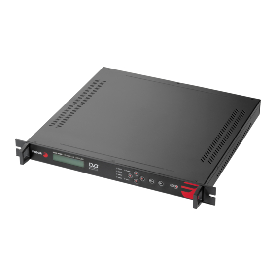
- Page 1 SRD 8 000 4x D VB-‐S/S2 S D/HD D ecoder ...
-
Page 2: Table Of Contents
TABLE OF CONTENTS SAFETY I NSTRUCTION ............................4 Overview ................................5 Technical S pecification ............................6 3.1. Input P ort ................................ 7 3.2. Output P ort ..............................7 ... - Page 3 6.6. Save C onfig ..............................18 6.7. Load C onfig ..............................18 6.7.1. Reload C onfig ............................18 6.7.2. Restore C onfig ............................18 6.8. Version ................................19 ...
-
Page 4: Safety I Nstruction
SAFETY I NSTRUCTION Read m anual c arefully b efore u se • Do n ot o pen t he c ase w ithout d isconnecting i t f rom t he m ains •... -
Page 5: Overview
1. Overview SRD 8000 4x SD/HD satellite decoder has 4×DVB-‐ S /S2 RF input interfaces and supports MPEG4 AVC/H.264 and MPEG2 video decoding and MPEG-‐ 1 , AAC audio decoding. The input satellite signal ... -
Page 6: Technical S Pecification
2. Technical S pecification Input RF DVB-‐S/S2 ( 950-‐2150MHz), F c onnector w ith L oop HDMI 4×HDMI 1 .3 Output CVBS 4× R CA c onnector Audio ... -
Page 7: Input P Ort
2.1. Input P ort 2.1.1. RF I N Input i nterface: 4 ×DVB-‐ S /S2, F -‐ h ead Connector: F -‐ h ead w ith l oop F o utput Impedance: ... -
Page 8: Equipment C Omposition
3. Equipment c omposition 3.1. FRONT P ANEL D ISPLAY A ND K EY B UTTON 1 2 3 4 5 6 1 LCD D isplay 2 ... -
Page 9: Installation G Uide
4. Installation G uide 4.1. Installation P reparation Check p ossible l ose o r d amage o f t he d evice d uring t ransportation a nd r ead t he c omplete u ser •... -
Page 10: Rack G Rounding
4.4. Rack G rounding Ground terminals of racks in one room should be separately connected to protective are copper bar provided by side board. And ground wire should be as far as possible short. If the wire is too long when installing, please cut off to avoid ground wire coiling. The sectional area of guide line of ground ... -
Page 11: Basic P Rogramming G Uide
5. BASIC P ROGRAMMING G UIDE 5.1. Lock S tatus D isplay 4 C H DMI D ecoder BR: 0 00.000.000.000 5.2. Press “ EXIT” t o E nter M enu After initialization, the menu shows as below (Press ‘up or down’ key to choose menu, then ... -
Page 12: Oscillator F Req
1.1.1. Oscillator F req. 1.1.2. Downlink F req. 1.1.3. Symbol R ate 1.1.4. Polarization 1.1.5. 22KHz 1.1.6. DisEqc 5.3.1.1. Oscillator F req. Move t he c ursor t o “ oscillator f req.” a nd e nter t he L NB f requency: 1.1.1. -
Page 13: 22Khz
5.3.1.5. 22KHz Move t he c ursor t o “ 22KHz” a nd s elect O FF o r O N f or L ow o r H igh B and: 1.1.5. ... -
Page 14: Playing P Rogram
5.4.1.1. Playing P rogram Move t he c ursor t o “ playing p rogram” a nd e nter i nto i t. T hen i t s hows a s b elow: 1.1. -
Page 15: Audio S Etting
5.4.1.2.3. Video A spect Move the cursor to “video aspect” and enter into it. Then it shows as below (Press ‘up or down’ ... - Page 16 5.4.1.3.1. Audio M ode Move the cursor to “audio mode” and enter into it. Then it shows as below (Press ‘up or down’ ...
-
Page 17: Network S Etting
5.5. Network S etting Move the cursor to “network setting” and enter into it. Then it shows as below (Press ‘up or down’ k ey t o c hoose m enu, t hen p ress t he ‘ enter’ k ey t o c onfirm): 3.1. ... -
Page 18: Mac A Ddress
5.5.5. MAC A ddress Move t he c ursor t o “ MAC a ddress” a nd e nter i nto i t. T hen i t s hows a s b elow: 3.5 ... -
Page 19: Version
5.8. Version Move t he c ursor t o “ version” a nd e nter i nto i t. T hen i t s hows a s b elow: 6. ... -
Page 20: Error I Nfo A Nd S Hooting
6. Error I nfo a nd S hooting 6.1. Indicator S tatus There a re 2 L ED i ndicators o n t he p anel: 1. -
Page 21: Nms O Peration G Uide
7. NMS O peration G uide Network Management System (NMS) can remotely set config and monitor the device. It can be u sed o nly a fter b eing a uthorized. Except ... - Page 22 Current N MS i s w ithout a ny d evice, u ser c an a dd p er h is d evice. I: M enu B ar IX: ...
-
Page 23: Add F Requency
7.2. Add F requency “Add Frequency”: all devices can be divided and managed by frequency. Click “Add Freq Node”, then a dialog for adding frequency shows up. Input a frequency, like 385MHZ”, and then ... -
Page 24: Edit D Evice
ADD “ 4-‐Channel H D D ecoder” Choose device type” ”, set device name (you can name as you like), 4-‐Channel HD Decoder and s et I P a ddress a nd P ort o f t he d evice. Y ou c an c heck I P a ddress b y c licking d own k ey on ... - Page 25 If config is wrong, please choose the device and then click “Edit Device”, then below dialog shows u p. M odify i t a nd t hen c lick “ OK” t o s ave. 2.
- Page 26 Here the ping is 192.168.0.20 (you can put your device IP address when you do it). Here we found 192.168.0.20 passed, which means there is already a device with 192.168.0.20. Then we ...
-
Page 27: Check A Nd S Et C Onfig
7.5. Check a nd S et C onfig Note: u ser h ad b etter d o t he f ollowing o peration b efore c onfiguring t he d evice: Click ... -
Page 28: Program S Etting
7.5.2. Program S etting “Get”: R ead c urrent c onfig f rom t he d evice. “Set”: C onfirm c onfig a nd e nable i t. ... -
Page 29: Public F Unction O F N Ms
7.6. Public F unction o f N MS Public function of NMS includes “Save Config”, “Restore Cong.”, “Reload Config”, “Import Config”, a nd “ Export C onfig”. ... - Page 30 and then import config from FLASH. At this moment, the config cannot be used. You need restart t he d evice o r c lick “ Reload C onfig” t o s tart n ew c onfig. “Export ...