Table of Contents
Advertisement
SPLIT-TYPE, HEAT PUMP AIR CONDITIONERS
FLOOR TYPE, HEAT PUMP AIR CONDITIONERS
SERVICE TECHNICAL GUIDE
Wireless type
Models
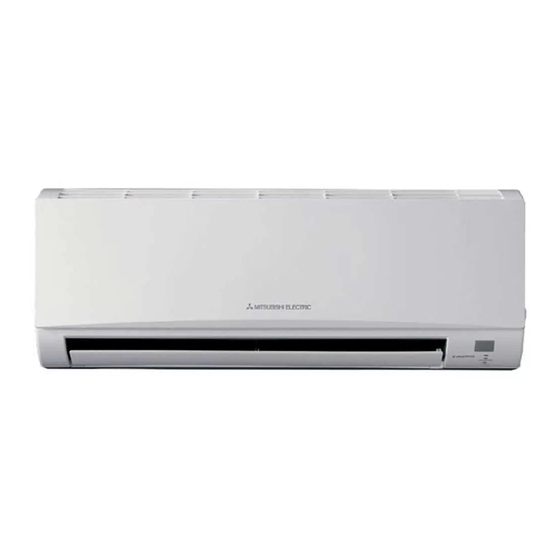
MSZ-FA•VA - · MUZ-FA•VA -
MSZ-GA•VA - · MUZ-GA•VA -
MFZ-KA•VA -
Inverter-controlled multi system type Models
Downloaded from AC-Manual.com Manuals
A
A
A
· MXZ-A•VA -
CONTENTS
1. MSZ-FA MICROPROCESSOR CONTROL ··········4
2. MSZ-GA MICROPROCESSOR CONTROL ·······22
3. MFZ MICROPROCESSOR CONTROL ··············50
4. MXZ MICROPROCESSOR CONTROL ··············62
Revision A:
MSZ-GA80VA has been added.
MUZ-GA•VA -
has been added.
A
MXZ-A•VA -
has been added.
A
Please void OBT14.
No. OBT14
REVISED EDITION-A
A
A
A
Advertisement
Table of Contents

Related Manuals for Mitsubishi MSZ-FA-VA


Summary of Contents for Mitsubishi MSZ-FA-VA
- Page 1 Revision A: MSZ-GA80VA has been added. MUZ-GA•VA - has been added. SPLIT-TYPE, HEAT PUMP AIR CONDITIONERS MXZ-A•VA - has been added. FLOOR TYPE, HEAT PUMP AIR CONDITIONERS Please void OBT14. No. OBT14 REVISED EDITION-A SERVICE TECHNICAL GUIDE Wireless type Models MSZ-FA•VA - ·...
-
Page 2: Table Of Contents
Revision A: • MSZ-GA80VA has been added. • MUZ-GA•VA - has been added. • MXZ-A•VA - has been added. 1. MSZ-FA MICROPROCESSOR CONTROL ···················································4 MSZ-FA·VA Indoor unit models Outdoor unit models As for outdoor unit MXZ-8A140VA, MSZ-FA25VA MUZ-FA25VA refer to service manual OC316. MSZ-FA35VA MUZ-FA35VA 1-1. - Page 3 3. MFZ MICROPROCESSOR CONTROL ·······················································50 MFZ-KA·VA Indoor unit models As for outdoor units SUZ-KA25VA.TH, MFZ-KA25VA SUZ-KA35VA.TH and SUZ-KA50VA.TH, MFZ-KA35VA refer to service manual OC323. MFZ-KA50VA 3-1. COOL OPERATION·············································································51 3-2. DRY OPERATION ···············································································52 3-3. HEAT OPERATION ·············································································52 3-4. AUTO CHANGE OVER ··· AUTO MODE OPERATION······················54 3-5.
-
Page 4: Msz-Fa Microprocessor Control
MSZ-FA MICROPROCESSOR CONTROL MSZ-FA25VA MUZ-FA25VA MSZ-FA35VA MUZ-FA35VA WIRELESS REMOTE CONTROLLER Signal transmitting section Operation display section OPERATE/STOP (ON/OFF) button Temperature buttons Indication of remote controller model (This diagram shows an overall view.) (This diagram shows an overall view.) WIDE VANE button (Vertical vane button) FAN SPEED CONTROL button OFF-TIMER button... -
Page 5: Cool Operation
1-1. COOL ( ) OPERATION (1) Press OPERATE/STOP(ON/OFF) button. POWER lamp of the indoor unit turns on with a beep tone. (2) Select COOL mode with OPERATION SELECT button. (3) Press TEMPERATURE buttons (TOO WARM or TOO COOL button)to select the desired temperature. The setting range is 16 ~ 31°C Difference between room temperature and set temper-... -
Page 6: Dry Operation
1-2. DRY ( ) OPERATION Set temperature and initial room temperature in dry mode (1) Press OPERATE/STOP(ON/OFF) button. POWER lamp of the indoor unit turns on with a beep tone. (2) Select DRY mode with OPERATION SELECT button. (3) The microprocessor reads the room temperature and determines the set temperature. - Page 7 3. High pressure protection In HEAT operation the indoor coil thermistor detects the temperature of the indoor heat exchanger. The compressor opera- tional frequency is controlled to prevent the condensing pressure from increasing excessively. 4. Overload starting When the room temperature thermistor RT11 reads 18°C or more, the compressor runs with its maximum frequency regulat- ed for 10 minutes after the start-up.
-
Page 8: Auto Change Over
1-4. AUTO CHANGE OVER ··· AUTO MODE OPERATION Once desired temperature is set, unit operation is switched automatically between COOL and HEAT operation. 1. Mode selection (1) Initial mode At first indoor unit operates only indoor fan with outdoor unit OFF for 3 minutes to detect present room temperature. Following the conditions below, operation mode is selected. -
Page 9: Auto Vane Operation
1-7. AUTO VANE OPERATION 1. Horizontal vane (1) Vane motor drive These models are equipped with a stepping motor for the horizontal vane. The rotating direction, speed, and angle of the motor are controlled by pulse signals (approximate 12V) transmitted from indoor microprocessor. (2) The horizontal vane angle and mode change as follows by pressing VANE CONTROL button. - Page 10 (9) To change the air flow direction not to blow directly onto your body. To change the air HEAT When to use this function? COOL/DRY flow direction Pressing and holding Use this function if you don’t The air conditioner starts the The air conditioner starts heat- want the air from the indoor cooling or drying operation...
-
Page 11: I-See Control Operation
2. Vertical vane (1) Vane motor drive These models are equipped with a stepping motor for the vertical vane. The rotating direction, speed, and angle of the motor are controlled by pulse signals (approximate 12V) transmitted from microprocessor. (2) The vertical vane angle and mode change as follows by pressing WIDE VANE button. (SWING) (3) Positioning The vane is once pressed to the vane stopper to confirm the standard position and then set to the desired angle. -
Page 12: Area Setting
1-9. AREA ( ) SETTING (1) Press OPERATE / STOP (ON/ OFF)button to start the air conditioner. (2) Press i-see button. (NOTE 1) (3) Press AREA button. Each time the button is pressed, the area is changed in sequence: (AUTO) (LEFT) (RIGHT) Cancel... - Page 13 (4) AREA setting is cancelled when the "cancel" is sellected by pressing AREA button, or when WIDE VANE button is pressed. Indoor unit installation location and air-conditioning area Installed at left Installed at center Installed at right LEFT RIGHT LEFT RIGHT LEFT RIGHT...
-
Page 14: Plasma Duo Operation
1-10. PLASMA DUO ( ) OPERATION (1) Press OPERATE/STOP (ON/OFF) button to start the air conditioner. PLASMA/WASH lamp (2) Press PLASMA button to set PLASMA DUO operation. Each time this b utton is pressed, the oper ation mode of PLASMA is changed in sequence: Lighted Cancel (The sign of PLASMA oper ation disappears .) -
Page 15: Auto Front Panel
1-11. AUTO FRONT PANEL When the unit starts operating, the front panel opens automatically to draw in air. When the unit stops operating, the front panel closes automatically. Open Closed Operation and operating range of the auto front panel The front panel fully opens 10 mm or more upper than the level line of the top end of the nozzle assembly. It takes about 13 seconds to open the front panel completely. -
Page 16: Emergency / Test Operation
PROGRAM TIMER • The OFF timer and ON timer can be used in combination. The timer of the set time that is reached first will operate first. • “ ” and “ ” display shows the order of the OFF timer and the ON timer operation. (Example 1) The current time is 8:00 PM. -
Page 17: Inverter System Control
1-14. INVERTER SYSTEM CONTROL 1-14-1. Inverter main power supply circuit POWER P.C. BOARD INVERTER P.C. BOARD DB61 Power R64A R64B C63A supply CT761 C63B C63C CT781 TR821 DB65 Booster chopper circucuit Function of main parts SYMBOL NAME FUNCTION It supplies three-phase AC power to compressor. INTELLIGENT POWER MODULE It stabilizes the DC voltage. - Page 18 3. Purpose of PAM adoption PAM : Pulse Amplitude Modulation PAM has been adopted for the efficiency improvement and the adaptation to IEC harmonic current emission standard. Outline of simple partial switching method In conventional inverter models, diode module rectifies AC voltage to DC voltage, smoothing capacitor makes its DC waveform smooth, and IPM converts its DC voltage to imitated AC voltage again in order to drive the compressor motor.
-
Page 19: Operational Frequency Control Of Outdoor Unit
1-14-3. Characteristics of sine wave control in case of brushless DC motor Although ordinary three-phase induction motor requires energy to excite the magnetic field of rotor, brushless DC motor doesn't need it. So, higher efficiency and torque are provided. This control provides the most efficient waveform corresponding to the rotation times of compressor motor. The rotation can be set to higher compared to the conventional motor drive system. -
Page 20: Expansion Valve Control (Lev Control)
1-16. EXPANSION VALVE CONTROL (LEV CONTROL) (1) Outline of LEV control The LEV basic control is comprised of setting LEV opening degree to the standard opening degrees set for each opera- tional frequency of the compressor. However, when any change in indoor/outdoor temperatures or other factors cause air conditioning load fluctuation, the LEV control also works to correct LEV opening degree based on discharge temper- ature (Shell temperature) of the compressor, developing the unit’s performance. - Page 21 (2) Time chart Air conditioner OFF (thermostat off) Air conditioner ON Positioning Opening degree is corrected according to discharge Standard Commanded temperature. opening to open degree about 5 minutes <COOL, DRY> Time about 15 minutes <HEAT> OFF Time (3) Control data (a) Reference value of target discharge temperature (COOL/HEAT :) Applied model...
-
Page 22: Msz-Ga Microprocessor Control
MSZ-GA MICROPROCESSOR CONTROL MSZ-GA22VA MSZ-GA25VA MUZ-GA25VA MSZ-GA35VA MUZ-GA35VA WIRELESS REMOTE CONTROLLER Signal transmitting section Operation display section OPERATE/STOP (ON/OFF) button Temperature buttons Indication of remote controller model is on back (This diagram shows an overall view.) FAN SPEED CONTROL button OFF-TIMER button OPERATION SELECT button ON-TIMER button... -
Page 23: Cool Operation
2-1. COOL ( ) OPERATION (1) Press OPERATE/STOP(ON/OFF) button. OPERATION INDICATOR lamp of the indoor unit turns on with a beep tone. (2) Select COOL mode with OPERATION SELECT button. (3) Press TEMPERATURE buttons (TOO WARM or TOO COOL button)to select the desired temperature. The setting range is 16 ~ 31°C Difference between room temperature and set temper-... -
Page 24: Dry Operation
Set temperature and 2-2. DRY ( ) OPERATION initial room temperature in dry mode (1) Press OPERATE/STOP(ON/OFF) button. OPERATION INDICATOR lamp of the indoor unit turns on with a beep tone. (2) Select DRY mode with OPERATION SELECT button. (3) The microprocessor reads the room temperature and determines the set temperature. - Page 25 3. High pressure protection In HEAT operation the indoor coil thermistor detects the temperature of the indoor heat exchanger. The compressor opera- tional frequency is controlled to prevent the condensing pressure from increasing excessively. 4. Overload starting When the room temperature thermistor RT11 reads 18°C or more, the compressor runs with its maximum frequency regulat- ed for 10 minutes after the start-up.
-
Page 26: Auto Change Over
Time chart of defrosting in HEAT mode (reverse type) <indoor unit> horizontal set position set position Horizontal vane Indoor fan Very Low (temperature of indoor coil thermistor > 18:) set speed set speed seconds <outdoor unit> Maximum frequency Compressor normal seconds seconds seconds... -
Page 27: Indoor Fan Motor Control
2-5. INDOOR FAN MOTOR CONTROL (1) Rotational frequency feedback control The indoor fan motor is equipped with a rotational frequency sensor, and outputs signal to the microprocessor to feedback the rotational frequency. Comparing the current rotational frequency with the target rotational frequency (Super High, High, Med., Low), the microprocessor adjusts fan motor electric current to make the current rotational frequency close to the target rotational frequency. - Page 28 (4) VANE AUTO ( ) mode In VANE AUTO mode, the microprocessor automatically determines the vane angle and operation to make the optimum room-temperature distribution. (1) In COOL and DRY operation Vane angle is fixed to Horizontal position. Horizontal position Vane angle is fixed to Angle 4.
-
Page 29: Timer Operation
(10) ECONO COOL ( ) operation (ECONOmical operation) When ECONO COOL button is pressed in COOL mode, set temperature is automatically set 2°C higher than that in COOL mode. Also the horizontal vane swings in various cycle according to the temperature of indoor heat exchanger(RT12). SWING operation makes you feel cooler than set temperature. -
Page 30: Emergency/Test Operation
PROGRAM TIMER • OFF timer and ON timer can be used in combination. The timer of the set time that is reached first will operate first. • “ ” and “ ” display shows the order of OFF timer and ON timer operation. (Example 1) The current time is 8:00 PM. -
Page 31: Inverter System Control
2-10. INVERTER SYSTEM CONTROL 2-10-1. Inverter main power supply circuit POWER P.C. BOARD INVERTER P.C. BOARD DB61 Power R64A R64B C63A supply CT761 C63B C63C CT781 TR821 DB65 Booster chopper circucuit Function of main parts SYMBOL NAME FUNCTION It supplies three-phase AC power to compressor. INTELLIGENT POWER MODULE It stabilizes the DC voltage. - Page 32 3. Purpose of PAM adoption PAM : Pulse Amplitude Modulation PAM has been adopted for the efficiency improvement and the adaptation to IEC harmonic current emission standard. Outline of simple partial switching method In conventional inverter models, diode module rectifies AC voltage to DC voltage, smoothing capacitor makes its DC waveform smooth, and IPM converts its DC voltage to imitated AC voltage again in order to drive the compressor motor.
-
Page 33: Operational Frequency Control Of Outdoor Unit
2-10-3. Characteristics of sine wave control in case of brushless DC motor Although ordinary three-phase induction motor requires energy to excite the magnetic field of rotor, brushless DC motor doesn't need it. So, higher efficiency and torque are provided. This control provides the most efficient waveform corresponding to the rotation times of compressor motor. The rotation can be set to higher compared to the conventional motor drive system. -
Page 34: Expansion Valve Control (Lev Control)
2-12. EXPANSION VALVE CONTROL (LEV CONTROL) MSZ-GA35 (1) Outline of LEV control The LEV basic control is comprised of setting LEV opening degree to the standard opening degrees set for each opera- tional frequency of the compressor. However, when any change in indoor/outdoor temperatures or other factors cause air conditioning load fluctuation, the LEV control also works to correct LEV opening degree based on discharge temper- ature (Shell temperature) of the compressor, developing the unit’s performance. - Page 35 (2) Time chart Air conditioner OFF (thermostat off) Air conditioner ON Positioning Opening degree is corrected according to discharge Standard Commanded temperature. opening to open degree about 5 minutes <COOL, DRY> Time about 15 minutes <HEAT> OFF Time (3) Control data (a) Reference value of target discharge temperature (COOL/HEAT Applied model...
-
Page 36: Cool Operation
MSZ-GA50VA MSZ-GA60VA MUZ-GA50VA MUZ-GA60VA MSZ-GA71VA MSZ-GA80VA MUZ-GA71VA MUZ-GA80VA WIRELESS REMOTE CONTROLLER Signal transmitting section Operation display section OPERATE /STOP (ON /OFF)button ON/OFF WARM COOL TEMPERATURE buttons Indication of remote controller model is on back. WIDE VANE button (Vertical vane button) FAN SPEED CONTROL button OFF-TIMER button OPERATION SELECT button... -
Page 37: Dry Operation
2. Indoor fan speed control Indoor fan operates continuously at the set speed by FAN SPEED CONTROL button Difference between room regardless of the thermostat’s OFF-ON. temperature and set tempera- In AUTO the fan speed is as follows. ture during operation ( Initial temperature difference Fan speed Room temperature minus set temperature : 1.7 : or more ········································High... -
Page 38: Heat Operation
Difference between room temperature and set tem- 1. Thermostat control perature during operation Thermostat is ON or OFF by difference between room temperature and set temperature. Initial temperature difference Thermostat Set temperature Room temperature minus set temperature : -1.0 : or more··············································ON Room temperature minus set temperature : less than -1.0 :············································OFF -1.0 -0.7... - Page 39 3. High pressure protection In HEAT operation the indoor coil thermistor detects the temperature of the indoor heat exchanger. The compressor opera- tional frequency is controlled to prevent the condensing pressure from increasing excessively. 4. Overload starting When the room temperature thermistor RT11 reads 18°C or more, the compressor runs with its maximum frequency regulat- ed for 10 minutes after the start-up.
-
Page 40: Auto Change Over
2-16. AUTO CHANGE OVER ··· AUTO MODE OPERATION Once desired temperature is set, unit operation is switched automatically between COOL and HEAT operation. 1. Mode selection (1) Initial mode At first indoor unit operates only indoor fan with outdoor unit OFF for 3 minutes to detect present room temperature. Following the conditions below, operation mode is selected. -
Page 41: Outdoor Fan Motor Control
2-18. OUTDOOR FAN MOTOR CONTROL Fan speed is switched according to the compressor frequency. Fan speed Down High Min. Compressor frequency Max. <Relation between compressor frequency and fan speed.> Indoor unit operation Mode Fan speed MUZ-GA50/60 MUZ-GA71/80 44Hz 54Hz COOL Down 33Hz 39Hz... - Page 42 (7) SWING MODE ( By selecting SWING mode with VANE CONTROL button, the horizontal vane swings vertically. The remote controller displays “ ” . SWING mode is cancelled when VANE CONTROL button is pressed once again. (8) Cold air prevention in HEAT operation. When any of the following conditions occurs in HEAT operation, the vane angle changes to Horizontal position automati- cally to prevent cold air blowing on users.
- Page 43 (10) LONG MODE ( By pressing LONG button indoor fan speed becomes faster than setting fan speed on the remote controller, and the hor- izontal vane moves to the position for LONG mode. The remote controller displays “ ”. LONG mode is cancelled when LONG button is pressed once again or VANE button is pressed or ECONO COOL button is pressed in COOL mode.
-
Page 44: Timer Operation
2-20. TIMER OPERATION 1. How to set the timer (1) Press OPERATE/STOP (ON/OFF) button to start the air conditioner. (2) Check that the current time is set correctly. NOTE : Timer operation will not work without setting the current time. Initially “AM0:00” blinks at the current time display of TIME MONITOR, so set the current time correctly with CLOCK SET button. -
Page 45: Emergency/Test Operation
2-21. EMERGENCY / TEST OPERATION In case of test run operation or emergency operation, use EMERGENCY OPERATION switch on the front of the indoor unit. Emergency operation is available when the remote controller is missing, has failed or the batteries of remote con- troller run down. - Page 46 2-22-2. Outline of main power supply circuit 1. At the start of operation Main power supply circuit is formed when X64 (Relay) is turned ON at compressor startup. To prevent rush current from running into the circuit when power supply is turned ON, R64A and R64B (Current-limiting resistor) are placed in sub circuit.
-
Page 47: Operational Frequency Control Of Outdoor Unit
2-22-4. Characteristics of sine wave control in case of brushless DC motor Although ordinary three-phase induction motor requires energy to excite the magnetic field of rotor, brushless DC motor doesn't need it. So, higher efficiency and torque are provided. This control provides the most efficient waveform corresponding to the rotation times of compressor motor. The rotation can be set to higher compared to the conventional motor drive system. -
Page 48: Expansion Valve Control (Lev Control)
2-24. EXPANSION VALVE CONTROL (LEV CONTROL) (1) Outline of LEV control The LEV basic control is comprised of setting LEV opening degree to the standard opening degrees set for each opera- tional frequency of the compressor. However, when any change in indoor/outdoor temperatures or other factors cause air conditioning load fluctuation, the LEV control also works to correct LEV opening degree based on discharge temper- ature (Shell temperature) of the compressor, developing the unit’s performance. - Page 49 (2) Time chart Air conditioner OFF (thermostat off) Air conditioner ON Positioning Opening degree is corrected according to discharge Standard Commanded temperature. opening to open degree about 5 minutes <COOL, DRY> Time about 15 minutes <HEAT> OFF Time (3) Control data (a) Reference value of target discharge temperature (COOL/HEAT :) Applied model...
-
Page 50: Mfz Microprocessor Control
MFZ MICROPROCESSOR CONTROL MFZ-KA25VA MFZ-KA35VA MFZ-KA50VA WIRELESS REMOTE CONTROLLER Signal transmitting section Operation display section OPERATE/STOP (ON/OFF) button Temperature buttons Indication of Open the front lid. remote controller model is on back verall view.) (This diagram shows an overall view.) .) i save button FAN SPEED CONTROL button OFF-TIMER button... -
Page 51: Cool Operation
3-1. COOL ( ) OPERATION (1) Press OPERATE/STOP(ON/OFF) button. OPERATION INDICATOR lamp of the indoor unit turns on with a beep tone. (2) Select COOL mode with OPERATION SELECT button. (3) Press TEMPERATURE buttons (TOO WARM or TOO COOL button)to select the desired temperature. The setting range is 16 ~ 31°C Difference between room temperature and set temper-... -
Page 52: Dry Operation
3-2. DRY ( ) OPERATION Set temperature and initial room temperature in dry mode (1) Press OPERATE/STOP(ON/OFF) button. OPERATION INDICATOR lamp of the indoor unit turns on with a beep tone. (2) Select DRY mode with OPERATION SELECT button. (3) The microprocessor reads the room temperature and determines the set temperature. - Page 53 2. Indoor fan speed control (1) Indoor fan operates at the set speed by FAN SPEED CONTROL button. Difference between room In Auto the fan speed is as follows. temperature and set tem- Fan speed perature during operation Initial temperature difference Set temperature minus room temperature: 2 : or more ··················································...
-
Page 54: Auto Change Over
Time chart of defrosting in HEAT mode (reverse type) <indoor unit> vertical set position set position Horizontal vane Indoor fan (upper) Very Low (temperature of indoor coil thermistor > 18:) set speed set speed seconds Indoor fan (lower) Damper OPEN or CLOSE OPEN or CLOSE CLOSE <outdoor unit>... -
Page 55: Indoor Fan Motor Control
3-5. INDOOR FAN MOTOR CONTROL (1) Rotational frequency feedback control The indoor fan motor is equipped with a rotational frequency sensor, and outputs signal to the microprocessor to feedback the rotational frequency. Comparing the current rotational frequency with the target rotational frequency (Super High, High, Med., Low), the microprocessor adjusts fan motor electric current to make the current rotational frequency close to the target rotational frequency. - Page 56 (4) VANE AUTO ( ) mode In VANE AUTO mode, the microprocessor automatically determines the vane angle and operation to make the optimum room-temperature distribution. (1) In COOL and DRY operation 1 1 2 2 Vane angle is fixed to Angle 1. (2) In HEAT operation When air comes out from upper air outlet, vane angle is fixed to...
- Page 57 (9) Damper operation NOTE 1 : Be sure to turn off the air conditioner before changing the switch setting. With this function, air comes out simultaneously from the upper and lower air outlets so that the room can be cooled or heated effectively. This function is set using the switch behind the front grille of the indoor unit.
- Page 58 (10) EMBEDDED INDOOR UNIT SETTING (MUST BE PERFORMED) • When installing a grating, use a grating with narrow upper and lower horizontal bars so that the airflow from the upper and lower air outlets does not contact the bars. If the horizontal bars will block the lower air outlet, use a stand, etc., to adjust the height of the indoor unit.
-
Page 59: I-Save Operation
<SWING operation> In swing operation of ECONO COOL operation mode, the initial air flow direction is adjusted to “Horizontal”. According to the temperature of indoor coil thermistor RT12 at starting of this operation, next downward blow time is decided. Then when the downward blow has been finished, next horizontal blow time is decided. For initial 10 minutes the swing operation is performed in table G~H for quick cooling. -
Page 60: Timer Operation
3-9. TIMER OPERATION 1. How to set the timer (1) Press OPERATE/STOP (ON/OFF) button to start the air conditioner. (2) Check that the current time is set correctly. NOTE : Timer operation will not work without setting the current time. Initially “AM0:00” blinks at the current time display of TIME MONITOR, so set the current time correctly with CLOCK SET button. -
Page 61: Emergency / Test Operation
3-10. EMERGENCY / TEST OPERATION In case of test run operation or emergency operation, use EMERGENCY OPERATION switch on the front of the indoor unit. Emergency operation is available when the remote controller is missing, has failed or the batteries of the remote controller run down. -
Page 62: Mxz Microprocessor Control
MXZ MICROPROCESSOR CONTROL MXZ-2A52VA MXZ-4A71VA MXZ-3A54VA MXZ-4A80VA 4-1. INVERTER SYSTEM CONTROL 4-1-1. MXZ-2A52VA 4-1-1-1. Inverter main power supply circuit POWER P.C. BOARD INVERTER P.C. BOARD CT61 DB61 Power C63A supply CT761 C63B C63C R64A R64B CT781 TR821 DB65 Booster chopper circucuit Function of main parts SYMBOL NAME... - Page 63 Outline of simple partial switching method In conventional inverter models, diode module rectifies AC voltage to DC voltage, smoothing capacitor makes its DC waveform smooth, and IPM converts its DC voltage to imitated AC voltage again in order to drive the compressor motor. However, it has been difficult to meet IEC harmonic current emission standard by above circuit because harmonic gets generated in the input current waveform and power factor gets down.
- Page 64 DC Motor AC Motor Permanent magnet is embedded. Excited by magnetic field of stator Rotor Rotor Position Signal Necessary Unnecessary w In brushless DC motor, permanent magnet is embedded in the rotor. Therefore, it doesn't require energy to excite the rotor like AC motor does.
- Page 65 3. Power factor improvement Booster coil L (Reactor) and PFC rectify AC to DC and control its voltage. In the motor drive system of sine wave control, power factor can be improved by reducing harmonics PFC and L (Reactor) stabilize the voltage of DC supplied to inverter circuit and make its waveform smooth. 4.
-
Page 66: Expansion Valve Control (Lev Control)
4-2. EXPANSION VALVE CONTROL (LEV CONTROL) Linear expansion valve (LEV) is controlled by "Thermostat ON" commands given from each unit. LEV opening Indoor unit status Stop of all indoor unit Opening before stop 500 pulse in 15 minutes When outdoor unit is operating, COOL : 5 pulse (full closed) some indoor units stop and HEAT (MXZ-2A) : 59 pulse (slightly opened) - Page 67 MXZ-3A/4A The table below shows the role of Exclusive LEV and Receiver LEV in each operation mode. wEvaporation High Circulation Discharge Capacity Amount Temperature Pressure Temperature Distribution Protection Protection Control Protection Exclusive LEV COOL Receiver LEV Exclusive LEV HEAT Receiver LEV Indoor heat Exclusive exchanger...
- Page 68 84 100 115 131 146 MXZ-2A/3A/4A71VA MXZ-4A80VA Compressor operating frequency (Hz) MXZ-2A52VA Standard opening (pulse) LEV Opening(code) COOL HEAT Difference in capacity Difference in operation number Code3,4 Code5,6 Code7,8 COOL HEAT -100 MXZ-3A54VA MXZ-4A71VA Standard opening (pulse) LEV Opening(code) COOL HEAT Difference in capacity Difference in operation number...
- Page 69 <Correction> COOL HEAT • • • 1 Discharge temperature 2 Each correction • • • (Each gas pipe temperature thermistor - Minimum gas pipe temperature thermistor)w 1 • (Main indoor coil thermistor - Sub indoor coil thermistor) w 1 Perform this, when number of operation units is 2 units or more. MXZ-2A52VA is excluded.
- Page 70 Correct the LEV opening according to the difference between target discharge temperature and discharge temperature. MXZ-2A52VA LEV opening correction (pulse) Discharge temperature (:) COOL HEAT More than Target discharge temperature+10 Target discharge temperature+10 to Target discharge temperature+5 Target discharge temperature+5 to Target discharge temperature+2 Target discharge temperature+2 to Target discharge temperature-2 Target discharge temperature-2 to Target discharge temperature-5...
-
Page 71: Operational Frequency Range
b) Correct the LEV separately by temperature difference “ RT” between main/sub indoor coil thermistor. LEV opening correction (pulse) RT< 6 RT<4 In addition, decrease the target discharge temperature corresponding Temperature to be decreased (:) RT< 6 RT<4 4-3. OPERATIONAL FREQUENCY RANGE MXZ-2A52VA Number of Capacity... -
Page 72: Heat Defrosting Control
MXZ-4A80VA Number of Capacity COOL (Hz) HEAT (Hz) operating code Min. Max. (Hz) Min. Max. Defrost unit 1, 2, 3, 4 5, 6 7, 8 9, 10 11, 12 13, 14 15 or above 2, 3, 4, 5, 6, 7 8, 9, 10 11, 12, 13 14, 15, 16... -
Page 73: Outdoor Fan Control
4-7. OUTDOOR FAN CONTROL Fan speed is switched according to the number of operating indoor unit and the compressor frequency. Fan speed Down High Min. Compressor frequency Max. <Relation between compressor frequency and fan speed.> Mode Fan speed Compressor frequency 40Hz COOL Down... - Page 74 HEAD OFFICE: TOKYO BLDG.,2-7-3, MARUNOUCHI, CHIYODA-KU, TOKYO100-8310, JAPAN C C Copyright 2005 MITSUBISHI ELECTRIC ENGINEERING CO.,LTD Distributed in Jan. 2006. No. OBT14 REVISED EDITION-A 7 New publication, effective Jan. 2006 Distributed in Aug. 2005. No. OBT14 8 Specifications subject to change without notice.