Table of Contents
Advertisement
SPLIT-TYPE, HEAT PUMP AIR CONDITIONERS
SERVICE MANUAL
Wireless type
Models
MSZ-FA25VA -
MSZ-FA35VA -
Indication of model name
MSZ-FA25VA -
MSZ-FA35VA -
NOTE:
This service manual describes technical data of the indoor units.
•As for outdoor units MUZ-FA25VA-
MUZ-FA35VAH-
•As for outdoor units MXZ-3A54VA-
refer to service manual OB377.
E1
E1
E1
E1
, MUZ-FA35VA-
E1
, refer to service manual OB372.
E1
, MXZ-4A71VA-
E1
(WH)
(WH)
CONTENTS
1. TECHNICAL CHANGES ····································2
2. PART NAMES AND FUNCTIONS······················3
3. SPECIFICATION·················································5
4. NOISE CRITERIA CURVES ·······························6
5. OUTLINES AND DIMENSIONS ·························7
6. WIRING DIAGRAM ············································8
7. REFRIGERANT SYSTEM DIAGRAM ················8
8. SERVICE FUNCTIONS ······································9
9. TROUBLESHOOTING······································11
10. DISASSEMBLY INSTRUCTIONS·····················31
11. PARTS LIST······················································35
12. OPTIONAL PARTS···········································38
, MUZ-FA25VAH-
E1
and MXZ-4A80VA-
E1
No. OB371
and
E1
,
E1
Advertisement
Table of Contents
Troubleshooting

Related Manuals for Mitsubishi MSZ-FA25VA


Summary of Contents for Mitsubishi MSZ-FA25VA
-
Page 1: Table Of Contents
SPLIT-TYPE, HEAT PUMP AIR CONDITIONERS SERVICE MANUAL Wireless type Models MSZ-FA25VA - MSZ-FA35VA - Indication of model name MSZ-FA25VA - MSZ-FA35VA - NOTE: This service manual describes technical data of the indoor units. •As for outdoor units MUZ-FA25VA- MUZ-FA35VAH- , refer to service manual OB372. -
Page 2: Technical Changes
TECHNICAL CHANGES MSZ-A09YV - MSZ-FA25VA - MSZ-A12YV - MSZ-FA35VA - 1. Indication of capacity has been changed.(BTU base 2. Controller method between indoor and outdoor has been changed. 3. Power supply method has been changed (change to supply from outdoor unit). -
Page 3: Part Names And Functions
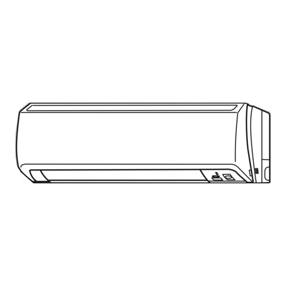
PART NAMES AND FUNCTIONS INDOOR UNIT MSZ-FA25VA - MSZ-FA35VA - PLASMA AIR PURIFYING filter Panel Heat exchanger Anti-mold air filter Air outlet Vertical vane Horizontal vane Line flow fan Auto front panel When the unit starts operating, the front panel opens automatically to draw in air. -
Page 4: Remote Controller
MSZ-FA25VA - MSZ-FA35VA - ACCESSORIES REMOTE CONTROLLER Open the front lid. Installation plate Installation plate fixing screw 4 o 25 mm Remote controller holder Fixing screw for 3 3.5 o 1.6 mm (Black) Battery (AAA) for remote controller Wireless remote controller... -
Page 5: Specification
(MT) Horizontal vane motor (MV1) Vertical vane motor (MV2) Varistor (NR11) i-see Sensor (RR) Terminal block (TB) MSZ-FA25VA - Cooling Heating Single phase 230V,50Hz 474 W /354 W /252 W 498 W /384 W /264 W 0.25 — 0.25 RC0J40-EB... -
Page 6: Noise Criteria Curves
NOISE CRITERIA CURVES MSZ-FA25VA - FAN SPEED FUNCTION COOLING Super High HEATING Test conditions, Cooling : Dry-bulb temperature 27: Wet-bulb temperature 19: Heating : Dry-bulb temperature 20: Wet-bulb temperature 15: APPROXIMATE THRESHOLD OF HEARING FOR CONTINUOUS NOISE BAND CENTER FREQUENCIES, Hz... -
Page 7: Outlines And Dimensions
OUTLINES AND DIMENSIONS MSZ-FA25VA - MSZ-FA35VA - INDOOR UNIT 53.5 624.5 Wireless remote controller 11o26 Oblong hole Installation plate Indoor unit Air out Required space (Indoor unit) 75 or more Unit : mm 11o20 Oblong hole Air in Wall hole Installation plate Liquid line [6.35 - 0.5m... -
Page 8: Wiring Diagram
WIRING DIAGRAM MSZ-FA25VA - MSZ-FA35VA - INDOOR UNIT 230V~ TO OUTDOOR UNIT 12-24V CONNECTING LD104 SYMBOL NAME DB111 DIODE STACK FUSE (T3.15AL250V) INDOOR FAN MOTOR FRONT PANEL DRIVING MOTOR i-see Sensor MOTOR VANE MOTOR (HORIZONTAL) NOTE:1. About the outdoor side electric wiring refer to the outdoor unit electric wiring diagram for servicing. -
Page 9: Service Functions
SERVICE FUNCTIONS MSZ-FA25VA - MSZ-FA35VA - 8-1. TIMER SHORT MODE For service, set time can be shortened by short circuit of JPG and JPS the electronic control P.C. board. The time will be shortened as follows. (Refer to 9-7.) Set time : 1-minute... - Page 10 Be sure to set the slide switch inside the remote controller to an appropriate position in accordance with the installed position of the indoor unit. If the switch is not set correctly, the air conditioner may not function properly. Side swich...
-
Page 11: Troubleshooting
2. Take care the following during servicing. 1) Before servicing the air conditioner, be sure to turn off the unit first with the remote controller, and then after confirming the horizontal vane is closed, turn off the breaker and / or disconnect the power plug. - Page 12 6. How to remove and install PLASMA DEODORIZING / AIR PURIFYING filter units If PLASMA/WASH lamp on the indoor unit blinks, clean the filters as soon as possible. The lamp will start blinking when accumulated operating time exceeds 330 hours. <Remove>...
- Page 13 INFORMATION FOR MULTI SYSTEM AIR CONDITIONER OUTDOOR UNIT : MXZ series Multi system air conditioner can connect two or more indoor units with one outdoor unit. •Unit won’t operate in case the total capacity of indoor units exceeds the capacity of outdoor units. Do not connect indoor units beyond the outdoor unit capacity.
-
Page 14: Failure Mode Recall Function
9-2. Failure mode recall function Outline of the function This air conditioner can memorize the abnormal condition which has occurred once. Even though LED indication listed on the troubleshooting check table disappears, the memorized failure details can be recalled. This mode is very useful when the unit needs to be repaired for the abnormality which doesn't recur. - Page 15 2. Flow chart of PLASMA DEODORIZING/PLASMA AIR PURIFYING power failure mode recall function Operational procedure There is a possibility that the plasma unit is abnormal. Confirm the presence of abnormality according to the following procedures. Confirm that the remote controller is in the failure mode recall function.
- Page 16 4. Indoor unit failure mode table NOTE: Blinking patterns of this mode differs from the ones of Troubleshooting check table(9-4.). Abnormal point POWER lamp (Failure mode) Not lighted Normal Room temperature 1-time flash thermistor every 0.5-second 2-time flash Indoor coil thermistor 2.5-second OFF 3-time flash Serial signal error...
- Page 17 9-3. Instruction of troubleshooting Start Indoor unit Indoor unit operates. operates. Outdoor unit doesn't Outdoor unit operate normally. doesn't operate. Outdoor unit Unit doesn't Outdoor unit doesn't operate operates in operate normal only Test Run operation. w even in operation in Test Run COOL or operation.
-
Page 18: Troubleshooting Check Table
9-4. Troubleshooting check table Lighted Blinking Not lighted NOTE : Before taking measures, make sure that the symptom reappears for accurate troubleshooting. Self check table Abnormal Operation indicator lamp point POWER lamp flashes. 0.5-second ON Mis-Wiring or serial signal 0.5-second OFF Outdoor control POWER lamp lights up... - Page 19 Lighted Blinking Not lighted NOTE : Before taking measures, make sure that the symptom reappears for accurate troubleshooting. Self check table Abnormal Operation indicator lamp point Left lamp of AREA lamp flashes. Indoor 4-time flash control system 2.5-second OFF Lighted Blinking Not lighted Abnormal...
- Page 20 9-5. Trouble criterion of main parts MSZ-FA25VA - MSZ-FA35VA - Part name Room temperature Measure the resistance with a tester. (Part temperature 10˚C ~ 30˚C) thermistor(RT11) Normal Indoor coil thermistor 8 k" ~ 20 k" (RT12(MAIN), RT13(SUB)) Check 9-6. A.
-
Page 21: Troubleshooting Flow
9-6. Troubleshooting flow When POWER lamp flashes 3-time. Indoor fan does not operate. Check of indoor fan motor The indoor fan motor error has occurred, and the indoor fan doesn't operate. Turn OFF the power supply. Insert a stick such as a screw driver into the air outlet, and check if there is any catch in the rotation of the line flow fan. -
Page 22: Check Of Remote Controller And Receiver P.c. Board
Indoor unit operates by pressing EMERGENCY OPERATION switch, but does not operate with the remote controller. Check of remote controller and receiver P.C. board wCheck if the remote controller is exclusive for this air conditioner. Switch on the remote controller. - Page 23 The unit does not operate with the remote controller. Also, POWER lamp does not light up by pressing EMERGENCY OPERATION switch. Check of indoor electronic control P.C. board and indoor fan motor Turn OFF the power supply. Remove indoor fan motor connector CN211, vane motor connector CN151 front panel driving motor connector connector CN1U1 and i-see Sensor motor connector CN110 from the indoor electronic...
-
Page 24: How To Check Mis-Wiring And Serial Signal Error
When POWER lamp flashes ON and OFF in every 0.5-second. Outdoor unit does not operate. How to check mis-wiring and serial signal error Inverter P.C.board (Parts side) Blinking · Turn OFF inverter-controlled lighting equipment. · Turn OFF the power supply and then turn ON again. - Page 25 When All lamps flash ON and OFF every 0.5-second. Indoor unit and outdoor unit do not operate. Check of installation of the horizontal vane Start Turn OFF the power supply. Is the stopper of the horizontal vane locked to the indoor unit correctly? To check the continuity of the interlock switch (Fan), measure the resistance of connector 1 - 2 connected to CN1R1 on the indoor...
- Page 26 After cleaning, make sure to attach the unit when it is Stays OFF completely dry. If the air conditioner goes ON with the plasma unit being wet, protection gets active and PLASMA/WASH lamp continuously flashes. Firmly fix the SAFETY DEVICE.
- Page 27 After cleaning, make sure to attach the unit when it is Stays OFF completely dry. If the air conditioner goes ON with the plasma unit being wet, protection gets active and PLASMA/WASH lamp continuously flashes. Firmly fix the SAFETY DEVICE.
- Page 28 Indoor unit and outdoor unit do not operate. Check of auto front panel Turn the remote controller ON. Does the front panel automatically open? (Does it start to move?) Is the front panel held 10mm or more upper than the level line of the nozzle top? Front panel is normal.
-
Page 29: Electromagnetic Noise Enters Into Tv Sets Or Radios
2.Channel, frequency, broadcast station affected by the electromagnetic noise 3.Channel, frequency, broadcast station unaffected by the electromagnetic noise 4.Layout of ; indoor/outdoor unit of the air conditioner, indoor/outdoor wiring, grounding wire, antennas, wiring from antennas, receiver 5.Electric field intensity of the broadcast station affected by the electromagnetic noise 6.Presence or absence of amplifier such as booster... - Page 30 9-7. Test point diagram and voltage MSZ-FA25VA - MSZ-FA35VA - Indoor electronic control P.C. board Power supply input 230V AC SW P.C. Board WASH reset switch(SW2) Emergency operation switch(SW1) Power monitor receiver P.C. board. Plasma power P.C. board High-voltage lead wire...
-
Page 31: Disassembly Instructions
The terminal without locking mechanism can be detached by pulling it out. Check the shape of the terminal before detaching. (1) Slide the sleeve and check if there is a locking lever or not. Sleeve Locking lever MSZ-FA25VA - MSZ-FA35VA - INDOOR UNIT OPERATING PROCEDURE 1. Removing the panel... - Page 32 OPERATING PROCEDURE 2. Removing the electronic control P.C. board, the power monitor receiver P.C. board, i-see Sensor, SW P.C. board and the terminal block (1) Remove the horizontal vane, the panel (Refer to 1.) and the corner box. (2) Remove the screw of the V.A. clamp, and then the indoor/outdoor connecting wire.(See Photo 3.) (3) Remove the switch holder from the electrical cover.
- Page 33 OPERATING PROCEDURE 4. Removing the horizontal vane motor unit (1) Remove the horizontal vane and the panel. (Refer to 1.) (2) Remove the screws of the horizontal vane motor unit, and pull out the horizontal vane motor unit. (See Photo 6.) (3) Disconnect the connector from the horizontal vane motor unit.
- Page 34 OPERATING PROCEDURE 7. Removing the plasma power P.C. board (1) Remove the horizontal vane, the panel (Refer to 1.) and the corner box. (2) Remove the switch holder and the electrical cover. (Refer to 3.) (3) Disconnect the connector of the front panel driving motor <CN1U1>...
-
Page 35: Parts List
PARTS LIST MSZ-FA25VA - (WH) MSZ-FA35VA - (WH) 11-1. INDOOR UNIT STRUCTURAL PARTS 11-1. INDOOR UNIT STRUCTURAL PARTS Part No. Part name E02 897 234 E02 913 000 PANEL ASSEMBLY (WH) E02 913 067 SCREW CAP E02 913 010 FRONT PANEL (WH) - Page 36 MSZ-FA25VA - (WH) MSZ-FA35VA - (WH) 11-3. INDOOR UNIT ELECTRICAL PARTS AND FUNCTIONAL PARTS SAFETY DEVICE (PLASMA UNIT) SLEEVE BEARING INTERLOCK SWITCH (FAN) POWER MONITOR RECEIVER P.C. BOARD POWER MONITOR RECEIVER P.C. BOARD HOLDER 11-4. INDOOR UNIT HEAT EXCHANGER PLASMA POWER P.C.BOARD...
- Page 37 E02 913 620 INDOOR HEAT EXCHANGER E02 914 620 INDOOR HEAT EXCHANGER UNION (GAS) E02 815 666 E02 151 667 UNION (LIQUID) Q'ty/unit Symbol in Wiring MSZ-FA25VA- MSZ-FA35VA- Diagram (WH) (WH) NR11 RT11 RT12, RT13 RT12, RT13 PLASMA_A PLASMA_D Remarks UP &...
-
Page 38: Optional Parts
(1) Release the two knobs to open the filter unit. (2) Pull the side knobs to outward and then forward to remove, as illustrated below. Model MSZ-FA25VA - MSZ-FA35VA - (3) Pull out the deodorizing ceramic filter from the side of the filter unit. - Page 40 HEAD OFFICE: MITSUBISHI DENKI BLDG., 2-2-3, MARUNOUCHI, CHIYODA-KU, TOKYO100-8310, JAPAN C C Copyright 2005 MITSUBISHI ELECTRIC ENGINEERING CO.,LTD Distributed in Jan. 2005. No. OB371 6 Made in Japan New publication, effective Jan. 2005 Specifications subject to change without notice.