
Related Manuals for Daikin VAM 150FAVE


Summary of Contents for Daikin VAM 150FAVE
- Page 1 SiE71-202 Service Manual Heat Recovery Ventilation VAM 150FAVE VAM 250FAVE VAM 350FAVE VAM 500FAVE VAM 650FAVE VAM 800FAVE VAM1000FAVE VAM1500FAVE VAM2000FAVE...
- Page 2 SiE71-202 Heat Recovery Ventilation VAM 150FAVE VAM 250FAVE VAM 350FAVE VAM 500FAVE VAM 650FAVE VAM 800FAVE VAM1000FAVE VAM1500FAVE VAM2000FAVE Table of Contents...
-
Page 3: Table Of Contents
SiE71-202 1. Introduction .....................v 1.1 Safety Cautions ..................v Part 1 General Constructions ............1 1. General Constructions ................2 1.1 Explanation....................2 Part 2 Product Specification ............5 1. Product Specification ................6 1.1 Specification .................... 6 Part 3 Operation ................9 1. Operation ....................10 1.1 Explanation for Systems................ - Page 4 SiE71-202 1.9 Data Transmission Error (Between LCD Remote Controller and Main Unit)......... 42 1.10 Data Transmission Error (LCD Remote Controller)....... 43 1.11 Data Transmission Error (Between LCD Master Remote Controller and Slave Remote Controller) ............... 44 1.12 Field Setting Error.................. 45 1.13 Overlapping Central Control Address............
- Page 5 SiE71-202 Table of Contents...
-
Page 6: Introduction
SiE71-202 Introduction 1. Introduction Safety Cautions Cautions and Be sure to read the following safety cautions before conducting repair work. Warnings The caution items are classified into “ Warning ” and “ Caution ”. The “ Warning ” items are especially important since they can lead to death or serious injury if they are not followed closely. The “... - Page 7 Introduction SiE71-202 1.1.1 Cautions in Operation and Maintenance WARNING WARNING WARNING Never inspect or service the unit by yourself. Do not change operations suddenly. It can result Ask a qualified service person to perform this work. not only in malfunction but also failure of switches or (The qualified service person) relays in the body.
- Page 8 SiE71-202 Introduction WARNING WARNING Do not use a HRV or an air suction/discharge grille in the following places. • Place subjected to high temperature • Place such as machinery plant or direct flame. and chemical plant where gas, Avoid a place where the temperature near which contains noxious gas or the HRV unit and the air suction/discharge corrosive components of mate -...
- Page 9 Introduction SiE71-202 1.1.2 Using Icons Icons are used to attract the attention of the reader to specific information. The meaning of each icon is described in the table below: 1.1.3 Using Icons List Icon Type of Description Information Note A “note” provides information that is not indispensable, but may nevertheless be valuable to the reader, such as tips and tricks.
-
Page 10: Part 1 General Constructions
SiE71-202 Part 1 General Constructions 1. General Constructions ................2 1.1 Explanation....................2 General Constructions... -
Page 11: General Constructions
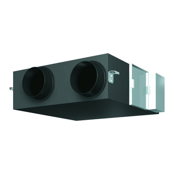
General Constructions SiE71-202 1. General Constructions Explanation VAM150FAVE VAM250FAVE VAM350FAVE VAM500FAVE VAM650FAVE VAM800FAVE VAM1000FAVE Ceiling Hock Duct Connection Flange Exhaust Fan Air Filter (Long Life Filter) Damper Switch Box Maintenance Cover Heat Exchange Elements Name Plate Air Supply Fan Remote Controller (Option Parts) Damper Motor EA (Exhaust Air) [Exhaust Air to Outdoor] OA (Outdoor Air) [Fresh Air from Outdoor]... - Page 12 SiE71-202 General Constructions VAM1500FAVE VAM2000FAVE Ceiling Hock Duct Connection Flange Exhaust Fan Air Filter (Long Life Filter) Damper Switch Box Maintenance Cover Heat Exchange Elements Name Plate Air Supply Fan Remote Controller (Option Parts) Damper Motor EA (Exhaust Air) [Exhaust Air to Outdoor] OA (Outdoor Air) [Fresh Air from Outdoor] Maintenance Space for The Air Filters, Heat RA (Return Air) [Exhaust Air from Room]...
- Page 13 General Constructions SiE71-202 General Constructions...
-
Page 14: Part 2 Product Specification
SiE71-202 Part 2 Product Specification 1. Product Specification ................6 1.1 Specification .................... 6 Product Specification... -
Page 15: Product Specification
Product Specification SiE71-202 1. Product Specification Specification (50 / 60Hz) Model Name VAM150FAVE VAM250FAVE VAM350FAVE Power Supply Single Phase 220 – 240 V / 220 V, 50 / 60 Hz Temperature Exchanging Ultra-High 74 / 74 72 / 72 75 / 75 Efficiency High 74 / 74... - Page 16 SiE71-202 Product Specification (50 / 60Hz) Model Name VAM500FAVE VAM650FAVE VAM800FAVE Power Supply Single Phase 220 – 240 V / 220 V, 50 / 60 Hz Temperature Exchanging Ultra-High 74 / 74 74 / 74 74 / 74 Efficiency High 74 / 74 74 / 74 74 / 74...
- Page 17 Product Specification SiE71-202 (50 / 60Hz) Model Name VAM1000FAVE VAM1500FAVE VAM2000FAVE Power Supply Single Phase 220 – 240 V / 220 V, 50 / 60 Hz Temperature Exchanging Ultra-High 75 / 75 75 / 75 75 / 75 Efficiency High 75 / 75 75 / 75 75 / 75...
- Page 18 SiE71-202 Part 3 Operation 1. Operation ....................10 1.1 Explanation for Systems................ 10 1.2 Operation HRV Units with The Remote Control exclusively for Air Conditioning Operation. (BRC301B61)........11 1.3 Operating The HRV Unit Using The Remote Controller of The VRV-System Air Conditioner ............13 1.4 Independent Operation of The HRV Unit Using The Centralized Controller (DCS302B61) ..........
-
Page 19: Operation
Operation SiE71-202 1. Operation Explanation for Systems This product is operated differently depending on the system configuration. For the operation of the remote controller for indoor unit and centralized controller, refer to the instruction manual provided with each unit. Operation for Each System System Example Operation Method Independent... -
Page 20: Operation Hrv Units With The Remote Control Exclusively For Air Conditioning Operation. (Brc301B61)
SiE71-202 Operation Operation HRV Units with The Remote Control exclusively for Air Conditioning Operation. (BRC301B61) For non-independent systems, starting/stopping operation and timer operation may not be possible. Use the air conditioner remote control or the Centralized controller in such cases. Remote Controller for HRV BRC301B61... - Page 21 Operation SiE71-202 4. Ventilation mode changeover: button “ ” (Automatic) mode ..The temperature sensor of the unit automatically changes the ventilation of the unit in [Bypass] mode and [Heat Exchange] mode. “ ” (Heat Exchange) mode ..In this mode, the air passes through the heat exchange element to effect [Total Heat Exchanging] ventilation.
-
Page 22: Operating The Hrv Unit Using The Remote Controller Of The Vrv-System Air Conditioner
SiE71-202 Operation Operating The HRV Unit Using The Remote Controller of The VRV-System Air Conditioner Remote Controller for VRV BRC1C51·61 1. Operation lamp 2. Operation/stop button 3. Air flow rate changeover button 4. Ventilation mode changeover button 5. Indication of air flow rate 6. -
Page 23: Independent Operation Of The Hrv Unit Using The Centralized Controller (Dcs302B61)
Operation SiE71-202 Remote Controller for VRV BRC1A51 1. Operation lamp 2. Operation/stop button 3. Operation mode display 4. Operation mode selector When the VRV-system air conditioner is connected with the HRV unit with a direct duct, the remote controller of the air conditioner cannot be used to select the VENTILATION mode. To use the HRV unit without operating the air conditioner, set the air conditioner in the FAN VENTILATION mode and select the low fan speed. -
Page 24: Part 4 Maintenance
SiE71-202 Part 4 Maintenance 1. Maintenance..................16 1.1 Maintenance for The Air Filter ............... 16 1.2 Maintenance for The Heat Exchange Element........18 Maintenance... -
Page 25: Maintenance
Maintenance SiE71-202 1. Maintenance Maintenance for The Air Filter Caution During operation, never check or clean the HRV. It may cause electrical shock and it is very dangerous to touch the rotating part. Be sure to turn off the OPERATION switch and disconnect the power. CLEANING FREQUENCY AT LEAST ONCE EVERY TWO YEARS (FOR GENERAL OFFICE USE) (CLEAN THE ELEMENT MORE FREQUENTLY IF NECESSARY.) - Page 26 SiE71-202 Maintenance 2. Take out the heat exchange elements from the unit body. VAM150 1000FAVE Heat Exchange Element (X2) Handle × Rail Filter VAM1500 2000FAVE Heat Exchange Element (X4) Handle × Rail Filter 3. To clean the air filter, lightly pat it with hand or remove dust with a vacuum cleaner. If excessively dirty, wash it in water.
-
Page 27: Maintenance For The Heat Exchange Element
Maintenance SiE71-202 5. Install the maintenance cover securely in place. Caution 1. Do not wash the air filter in hot water. 2. Do not dry the air filter over a fire. 3. Do not expose the air filter to direct sunlight. 4. -
Page 28: Part 5 Control Functions
SiE71-202 Part 5 Control Functions 1. Control Functions ..................20 1.1 List of Control Functions................ 20 1.2 Explanation of Individual Functions ............21 1.3 Layout of switches on Printed Circuit Board.......... 27 Control Functions... -
Page 29: Control Functions
Control Functions SiE71-202 1. Control Functions List of Control Functions Classification Function name Outline of function 1. Basic functions 1.1 Ventilation Controls supply air fan motor, exhaust air fan motor and damper (functions related to operation control motor. basic performance) function 1.2 Abnormality Detects abnormalities in thermistor, damper motor and data... -
Page 30: Explanation Of Individual Functions
SiE71-202 Control Functions Explanation of Individual Functions 1.2.1 Ventilation Operation Control Controls ventilation fan motors (supply and exhaust air fans) and damper motor. 1) Normal operation Operation chart Filter sign Cleaning Normal ventilation Operation reset time Stop mode selection Ventilation fan motor Damper motor Total heat (ventilation mode) - Page 31 Control Functions SiE71-202 1.2.2 Pre-cool/Pre-heat Pre-cool/pre-heat operations require the following conditions. 1. System Pre-heat operation is possible only in air conditioner linked system (1 group, 2-group link). Check the system first. 2. Heat recovery ventilation setting Set Preheat ON/OFF to ON. Pre-cool/pre-heat On/OFF setting can be made in air conditioner or using field setting mode of LCD remote controller of heat recovery ventilation unit.
- Page 32 SiE71-202 Control Functions 1.2.3 Cold Area Mode Stops or lowers ventilation airflow during defrosting operation and compressor non-operating condition when equipment in heating mode, thus reducing heating load and cold air draft. Operation chart (in heating operation only) Normal ventilation Operation Defrosting operation mode selection...
- Page 33 Control Functions SiE71-202 2) Link control of 2 or more groups (zone link) Heat recovery ventilation unit can be operated when one or more air conditioners are operating. Allows independent operation of heat recovery ventilation unit from VRV-system remote controller during interim periods (direct duct connection is not allowed in this system).
- Page 34 SiE71-202 Control Functions Details of setting Mode Setting Setting Setting position Operation method mode switch Indication of Field 18(28) Indication — — — — ventilation mode / Indication setting Not indication Refer to P54 Fresh up air Indication Indication — —...
- Page 35 Control Functions SiE71-202 1.2.6 External Damper Operation (FIELD SUPPLY) Explanation of Intake of outdoor air can be prevented when HRV is switched OFF if this damper is incorporated in the Functions system. 1. The total heat exchanger’s main unit print board supplies power for external damper. External damper Switch box Inspection...
-
Page 36: Layout Of Switches On Printed Circuit Board
SiE71-202 Control Functions Layout of switches on Printed Circuit Board 1.3.1 Printed Circuit Board Dumper Dumper Primary Secondary Supply Exhaust air fan air fan Outdoor Thermistor Indoor Thermistor Dumper 2 Dumper 1 KRP50-2 Power supply Factory setting REMOTE CENTRAIZD THE INPUT Be sure to give CONTROLLER CONTROL... - Page 37 Control Functions SiE71-202 Control Functions...
-
Page 38: Part 6 Circuit Operations
SiE71-202 Part 6 Circuit Operations 1. Circuit Operations .................30 1.1 Circuit Configuration ................30 1.2 Circuit Functions..................31 Circuit Operations... -
Page 39: Circuit Operations
Circuit Operations SiE71-202 1. Circuit Operations Circuit Configuration Fan motor Damper motor PCB assembly Fan motor, Transformer damper motor relay Detection and cut-off of+16V current +16V Power supply Thermistor + 5V circuit Thermistor interface circuit To circuits and Relay drive microcomputer circuit Centralized control... -
Page 40: Circuit Functions
SiE71-202 Circuit Operations Circuit Functions Classification Circuit Function Input/output Central data transmission interface Used by centralized control equipment for operation control. Allows control of up to 64 groups of air conditioners and heat recovery ventilation units. Use of KRP2A61 allows zone link operation. - Page 41 Circuit Operations SiE71-202 Circuit Operations...
-
Page 42: Part 7 Troubleshooting
SiE71-202 Part 7 Troubleshooting 1. Troubleshooting ..................34 1.1 Error Code Indication................34 1.2 Overall Alarm..................35 1.3 Overall Malfunction................36 1.4 Indoor Air Thermistor Error..............37 1.5 Outdoor Air Thermistor Error ..............38 1.6 Damper System Error (Alarm) ............... 39 1.7 Damper System Error (Alarm) ............... -
Page 43: Troubleshooting
Troubleshooting SiE71-202 1. Troubleshooting Error Code Indication When an abnormality is generated, take necessary measures by referring to displayed error code. After the cause of abnormality is removed, operate equipment and check proper functioning. Indication of unit No. of abnormal Inspection indication Error code heat recovery ventilation unit... -
Page 44: Overall Alarm
SiE71-202 Troubleshooting Overall Alarm — Remote Controller Error Code Inspection Unit No. LCD Display LED Indication Remote Controller Main Unit Error Detection Abnormalities are detected based on open circuit in external input terminals (J1-JC). Method Error Generating When external input terminal (J1-JC) short-circuit during operation Conditions (“Overall Alarm”... -
Page 45: Overall Malfunction
Troubleshooting SiE71-202 Overall Malfunction Remote Controller Error Code Inspection Unit No. LCD Display LED Indication Remote Controller Main Unit Error Detection Errors are detected based on open circuit in external input terminals (J1-JC). Method Error Generating When external input terminal (J1-JC) short-circuit during operation (“Overall Alarm” must be set in field Conditions setting mode). -
Page 46: Indoor Air Thermistor Error
SiE71-202 Troubleshooting Indoor Air Thermistor Error — Remote Controller Error Code Inspection Unit No. LCD Display LED Indication Remote Controller Main Unit Error Detection Temperature detected by inside air temperature sensor is used to detect errors. Method Error Generating When value detected by inside air temperature sensor is -40ºC or below (open circuit) or 70ºC or higher Conditions (short-circuit). -
Page 47: Outdoor Air Thermistor Error
Troubleshooting SiE71-202 Outdoor Air Thermistor Error — Remote Controller Error Code Inspection Unit No. LCD Display LED Indication Remote Controller Main Unit Error Detection Temperature detected by outside air temperature sensor is used to detect errors. Method Error Generating When value detected by outside air temperature sensor is -40ºC or below (open circuit) or 70ºC or higher Conditions (short-circuit). -
Page 48: Damper System Error (Alarm)
SiE71-202 Troubleshooting Damper System Error (Alarm) — Remote Controller Error Code Inspection Unit No. LCD Display LED Indication Remote Controller Main Unit Error Detection Measurement of damper motor limit ON/OFF time. Method Error Generating When damper motor limit switch 1 (or 2) remains ON (or OFF) for more than a certain time duration Conditions after ventilation mode is changed. -
Page 49: Damper System Error (Alarm)
Troubleshooting SiE71-202 Damper System Error (Alarm) Remote Controller Error Code Inspection Unit No. LCD Display LED Indication Remote Controller Main Unit Error Detection Measurement of damper motor limit switch ON/OFF time and temperatures detected by outdoor and indoor Method air thermistor. Error Generating When damper system error (alarm) and indoor (or outdoor) thermistor error are generated at the same Conditions... -
Page 50: Dedicated Lcd Remote Controller
SiE71-202 Troubleshooting Dedicated LCD Remote Controller When “ ” remains on remote controller display. Error Detection When “ ” remains on remote controller display. Method Error Generating Conditions Possible Causes Master-slave setting of remote controller Remote controller PCB assembly error Main unit PCB assembly error Troubleshooting Check to see if master-... -
Page 51: Data Transmission Error (Between Lcd Remote Controller And Main Unit)
Troubleshooting SiE71-202 Data Transmission Error (Between LCD Remote Controller and Main Unit) Remote Controller Error Code Inspection Unit No. LCD Display LED Indication Remote Controller Main Unit Error Detection Microcomputer checks if data is transmitted properly between main unit and remote controller. Method Error Generating When data transmission is not performed correctly for a certain time period. -
Page 52: Data Transmission Error (Lcd Remote Controller)
SiE71-202 Troubleshooting 1.10 Data Transmission Error (LCD Remote Controller) Remote Controller Error Code Inspection Unit No. LCD Display LED Indication Remote Controller Main Unit Error Detection Microcomputer checks if data is transmitted properly between main unit and remote controller. Method Error Generating When data transmission is not performed correctly for a certain time period. -
Page 53: Data Transmission Error (Between Lcd Master Remote Controller And Slave Remote Controller)
Troubleshooting SiE71-202 1.11 Data Transmission Error (Between LCD Master Remote Controller and Slave Remote Controller) Remote Controller Error Code Inspection Unit No. LCD Display LED Indication Remote Controller Main Unit Error Detection Microcomputer checks if data is transmitted properly between master-slave remote controller. Method Error Generating When data transmission is not performed correctly for a certain time period. -
Page 54: Field Setting Error
SiE71-202 Troubleshooting 1.12 Field Setting Error Remote Controller Error Code Inspection Unit No. LCD Display LED Indication Remote Controller Main Unit Error Detection Method Error Generating Conditions Possible Causes Faulty combination of remote controller More than 16 units connected to remote controller cable. Faulty remote controller Troubleshooting combination... -
Page 55: Overlapping Central Control Address
Troubleshooting SiE71-202 1.13 Overlapping Central Control Address Remote Controller Error Code Inspection Unit No. LCD Display LED Indication Remote Controller Main Unit Error Detection Remote controller microcomputer checks for double-setting of addresses. Method Error Generating When same address is set to two or more units. Conditions Possible Causes Overlapping of central control address... -
Page 56: Main Unit Pcb Assembly
SiE71-202 Troubleshooting 1.14 Main Unit PCB Assembly Error Detection Check microcomputer operation monitor. Method Error Generating When main unit PCB assembly does not operate. Conditions When communication circuit errors. Possible Causes Fuse (excess current) Power transformer Noise Main unit PCB Troubleshooting Turn off power, then restart. -
Page 57: Dedicated Lcd Remote Controller
Troubleshooting SiE71-202 1.15 Dedicated LCD Remote Controller When no indication is displayed on remote controller Error Detection Check to see if remote controller displays indication. Method Error Generating Conditions Possible Causes Troubleshooting Disconnect remote controller cable from both main unit terminal board and remote controller terminal board. -
Page 58: How To Check
SiE71-202 Troubleshooting 1.16 How to Check Check 1 Dedicated LCD remote controller (Option) Main unit PCB (HL034) Check 2 Dedicated LCD remote controller (Option) Main unit PCB (HL035) Check 3 Dedicated LCD remote controller (Option) LCD remote controller Remote controller for heat recovery ventilation Main unit PCB (HL036) -
Page 59: Thermistor
Troubleshooting SiE71-202 1.17 Thermistor Error Detection Remove thermistor and check resistance with tester. Method Error Generating Conditions Possible Causes Faulty thermistor Broken wire Faulty control PCB Faulty contact in connector Troubleshooting Remove thermistor from main unit PCB (X12A, X13A), and check resistance using tester. -
Page 60: Power Transformer
SiE71-202 Troubleshooting 1.18 Power Transformer Error Detection Check resistance and voltage with tester, and insulation resistance with megger. Method Error Generating Conditions Possible Causes Troubleshooting Check resistance of primary side of transformer. Does measured resistance deviate significantly Transformer is faulty. from values shown below? -
Page 61: Damper Motor
Troubleshooting SiE71-202 1.19 Damper Motor Error Detection Check damper motor and limit switch when damper motor does not operate. Method Error Generating Conditions Possible Causes Troubleshooting Place tester probes at connectors of limit switch, and check continuity while moving switch by hand. -
Page 62: Part 8 Supplementary Explanation
SiE71-202 Part 8 Supplementary Explanation 1. Supplementary Explanation ..............54 1.1 Field Setting, Service Mode Operation..........54 Supplementary Explanation... -
Page 63: Supplementary Explanation
Supplementary Explanation SiE71-202 1. Supplementary Explanation Field Setting, Service Mode Operation 1.1.1 Field Setting Initial setting (mode Nos. 17, 27, 18, 28) Field setting mode Unit No. Setting position No. Setting switch No. Mode No. 1, 7 (HL039) Step 1 With equipment in normal mode, press the button for more than 4 seconds to enter field setting mode. - Page 64 SiE71-202 Supplementary Explanation Centralized control group No. setting Field setting mode (Mode No. 00) Setting of Individual No. (Mode No. 30) Group No. Mode No. 1, 5 (HL040) Step 1 With equipment in normal mode, press the button for more than 4 seconds to enter field setting mode.
- Page 65 Supplementary Explanation SiE71-202 1.1.2 Service Mode Operation Turn on the forced fan (Mode No.43) Mode No. Unit No. 1, 4 (HL041) Step 1 With equipment in field setting mode, press the button for more than 4 seconds to enter service mode. ↔...
- Page 66 SiE71-202 Supplementary Explanation Unit No. reallocation (Mode Field setting mode No.45) Unit No. before reallocation Unit No. after reallocation Mode No. 1, 6 (HL042) Step 1 With equipment in field setting mode, press the button for more than 4 seconds to enter service mode.
- Page 67 Supplementary Explanation SiE71-202 1.1.3 Operation Changeover Control For group control of systems containing heat recovery ventilation units and air conditioners (VRV system), remote controllers of air conditioners are connected with remote controllers of new heat recovery ventilation units. In such system, both remote controllers display “Operation changeover control” according to the ON/OFF of cooling/heating selection privilege.
- Page 68 SiE71-202 Supplementary Explanation 1.1.4 Field Setting The following shows the procedure for field setting using remote controller of new heat recovery ventilation unit. (HL044) List of field setting mode Nos. Centralized control group No. setting General setting 10-29 Centralized control group No. setting (group) Error record display Sensor data Forced fan ON...
- Page 69 Supplementary Explanation SiE71-202 1.1.5 LCD and Operation Panel (Reference Information) The following shows the operation panel and LCD of remote controller of new heat recovery ventilation unit. (HL045) LCD is equipped with a new function that graphically displays currently selected ventilation mode, as shown below.
- Page 70 SiE71-202 Supplementary Explanation 1.1.6 Ventilation Volume (Freshup) Ventilation volume (Freshup) setting (With Freshup) (Without Freshup) changes as follows. High High Freshup Function modes change in sequence every time button is pressed. High Freshup (HL051) Inspection Inspection operation is shown below. Unit Cyclic (Normal screen)
- Page 71 Supplementary Explanation SiE71-202 1.1.7 Field Setting (Example of setting operation) Centralized control 1. Press for more than 4 seconds. group No. setting 2. Set mode No. to “00” using (mode No.: 00) 3. Set centralized control group No. using ] or 4.
- Page 72 SiE71-202 Supplementary Explanation Individual Settings Heat Recovery Ventilation Unit Air Conditioner Ventilation Volume Ventilation Mode Airflow Volume Airflow Direction As indicated by LCD As indicated by LCD High Swing Supplementary Explanation...
- Page 73 Supplementary Explanation SiE71-202 Supplementary Explanation...
-
Page 74: Part 9 Appendix
SiE71-202 Part 9 Appendix 1. Appendix ....................66 1.1 Wiring Diagram..................66 Appendix... -
Page 75: Appendix
Appendix SiE71-202 1. Appendix Wiring Diagram VAM150FAVE / VAM250FAVE / VAM350FAVE / VAM500FAVE / VAM650FAVE / VAM800FAVE / VAM1000FAVE Appendix... - Page 76 SiE71-202 Appendix VAM1500FAVE / VAM2000FAVE Appendix...
- Page 77 Appendix SiE71-202 Appendix...
-
Page 78: Index
SiE71-202 Index Abnormality control function ........20 EEPROM ............... 31 Air conditioner link function ........20 Electric heater setting ..........25 Air Conditioner Link Operation .......23 Error Code 60 ..........35, 36 Air conditioner link operation ........31 Error Code 64 ............37 Air Filter (Long Life Filter) ........2, 3 Error Code 65 ............ - Page 79 SiE71-202 How to Check ............49 Overall Malfunction ..........36 HOW TO OPERATE WITH TIMER ......12 Overlapping Central Control Address ....46 Humidifier operation control function ......20 Power ON operation function ........ 20 Independent Operation of The HRV Unit Power supply circuit ..........31 Using The Centralized Controller Power Transformer ..........
- Page 80 SiE71-202 Ventilation mode Total heat exchange ........60 When no indication is displayed Ventilation mode changeover function ....20 on remote controller ........48 Ventilation mode setting .........25 Ventilation Operation Control .........21 Ventilation operation control function .....20 Yes / No setting for direct duct Connection Ventilation volume (Freshup) setting changes ..61 with VRV system ..........
- Page 81 SiE71-202 Index...
-
Page 82: Drawings & Flow Charts
SiE71-202 Drawings & Flow Charts VAM2000FAVE ..........3 VAM250FAVE ........... 2 Air Conditioner Link Operation VAM350FAVE ........... 2 1 group link control ..........23 VAM500FAVE ........... 2 Link control of 2 or more groups ......24 VAM650FAVE ........... 2 Air flow rate can be changed over ......11 VAM800FAVE ........... - Page 83 SiE71-202 Unit No. reallocation (Mode No.45) ......57 When “88” remains on remote controller display .. 41 Use tester to check resistance ......37 When no indication is displayed on remote controller ........48 Wiring Diagram Ventilation mode VAM1500FAVE / VAM2000FAVE ....67 Total heat exchange ........60 VAM150FAVE / VAM250FAVE / Ventilation mode changeover ........12...
- Page 84 Daikin Europe N.V. is approved by LRQA for its Quality Daikin units comply with the European regulations that Management System in accordance with the ISO9001 guarantee the safety of the product. standard. ISO9001 pertains to quality assurance regarding design, development, manufacturing as well as to services related to the product.