Dell PowerEdge R630 Owner's Manual
Hide thumbs
Also See for PowerEdge R630:
- Owner's manual (197 pages) ,
- Technical manual (59 pages) ,
- Installing manual (18 pages)

Related Manuals for Dell PowerEdge R630


Summary of Contents for Dell PowerEdge R630
- Page 1 Dell PowerEdge R630 Owner's Manual Regulatory Model: E26S Series Regulatory Type: E26S001...
- Page 2 © 2016 Dell Inc. All rights reserved. This product is protected by U.S. and international copyright and intellectual property laws. Dell and the Dell logo are trademarks of Dell Inc. in the United States and/or other jurisdictions. All other marks and names mentioned herein may be trademarks of their respective companies.
-
Page 3: Table Of Contents
Contents 1 Dell PowerEdge R630 system overview............9 ...............9 Supported configurations for the PowerEdge R630 system ............................10 Front panel ....................11 10 x 2.5-inch hard drive chassis ....................13 Eight x 2.5-inch hard drive chassis ....................15 24 x 1.8-inch hard drive chassis ............................17... - Page 4 System Setup details ..........................50 System BIOS ........................74 iDRAC Settings utility ..........................74 Device Settings ........................75 Dell Lifecycle Controller ....................75 Embedded system management ............................75 Boot Manager ........................75 Viewing Boot Manager ......................76 Boot Manager main menu ..............................
- Page 5 ...................... 86 Removing the cooling shroud ......................87 Installing the cooling shroud ..........................87 System memory .................89 General memory module installation guidelines ......................90 Mode-specific guidelines ....................91 Sample memory configurations ......................94 Removing memory modules ......................95 Installing memory modules ............................97 Hard drives ..................97...
- Page 6 ....................127 Integrated storage controller card ..............127 Removing the integrated storage controller card ............... 129 Installing the integrated storage controller card ........................131 Network daughter card ..................131 Removing the network daughter card ..................132 Installing the network daughter card .........................134 Processors and heat sinks ........................
- Page 7 ....................183 Dell Embedded System Diagnostics ..........183 Running the Embedded System Diagnostics from Boot Manager .....183 Running the Embedded System Diagnostics from the Dell Lifecycle Controller ....................... 184 System diagnostics controls 8 Jumpers and connectors ................185 ......................185 System board jumper settings ...................
- Page 8 ........................ 206 Documentation feedback .................. 206 Accessing system information by using QRL ..................... 207 Quick Resource Locator for R630...
-
Page 9: Dell Poweredge R630 System Overview
24 DIMM slots supporting up to 1536 GB of memory • Two AC or DC redundant power supply units NOTE: The Dell PowerEdge R630 system supports hot swappable hard drives. Supported configurations for the PowerEdge R630 system The Dell PowerEdge R630 system supports the following configurations:... -
Page 10: Front Panel
Figure 1. Supported configurations for the PowerEdge R630 system Front panel... -
Page 11: 10 X 2.5-Inch Hard Drive Chassis
10 x 2.5-inch hard drive chassis Figure 2. Front panel features of the 10 x 2.5-inch hard drive PowerEdge R630 chassis Diagnostic indicators System health indicator Power-on indicator, power button NMI button System identification button Micro USB port/iDRAC Direct Information tag... - Page 12 Micro USB port/iDRAC Enables you to connect USB devices to the system Direct or provides access to the iDRAC Direct features. For more information, see the Integrated Dell Remote Access Controller User's Guide at Dell.com/idracmanuals. The port is USB 3.0- compliant.
-
Page 13: Eight X 2.5-Inch Hard Drive Chassis
Eight x 2.5-inch hard drive chassis Figure 3. Front panel features of the eight x 2.5-inch PowerEdge R630 hard drive chassis Power-on indicator, power button NMI button System identification button USB management port or iDRAC Direct (2) Optical drive (optional) - Page 14 USB management port/ Functions as a regular USB port or provides access iDRAC Direct (2) to the iDRAC Direct features. For more information, see the iDRAC Guide at Dell.com/ idracmanuals. The ports are USB 3.0-compliant. Optical drive (optional) One optional SATA DVD-ROM drive or DVD+/-RW drive.
-
Page 15: 24 X 1.8-Inch Hard Drive Chassis
For more information, see the Integrated Dell Remote Access Controller User’s Guide at Dell.com/idracmanuals. 24 x 1.8-inch hard drive chassis Figure 4. Front panel features of the 24 x 1.8-inch hard drive PowerEdge R630 chassis Diagnostic indicators System health indicator Power-on indicator, power button... - Page 16 Micro USB port Enables you to connect USB devices to the system or provides access to the iDRAC Direct features. For more information, see the Integrated Dell Remote Access Controller User's Guide at Dell.com/idracmanuals. The port is USB 3.0- compliant. Information tag Contains system information such as service tag, NIC, MAC address for your reference.
-
Page 17: Lcd Panel
The LCD panel of your system provides system information, status, and error messages to indicate if the system is functioning correctly or if the system needs attention. For more information about error messages, see the Dell Event and Error Messages Reference Guide at Dell.com/ openmanagemanuals >OpenManage software. - Page 18 SEL. This enables you to match an LCD message with an SEL entry. Select Simple to view LCD error messages in a simplified user-friendly description. For more information about error messages, see the Dell Event and Error Messages Reference Guide at Dell.com/openmanagemanuals > OpenManage software. Set home Select the default information to be displayed on the Home screen.
-
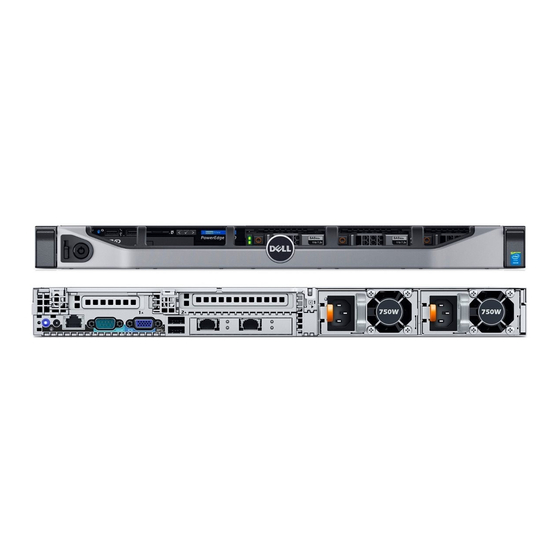
Page 19: Back Panel
Option Description Power Displays the power output of the system in BTU/hr or Watts. The display format can be configured in the Set home submenu of the Setup menu. Temperature Displays the temperature of the system in Celsius or Fahrenheit. The display format can be configured in the Set home submenu of the Setup menu. - Page 20 Item Indicator, Button, or Icon Description Connector To reset iDRAC (if not disabled in F2 iDRAC setup), press and hold for more than 15 seconds. System identification Enables you to connect the optional system status connector indicator assembly through the optional cable management arm.
-
Page 21: Three-Riser Chassis
Item Indicator, Button, or Icon Description Connector • Two 750 W mixed mode PSUs Related Links Expansion card installation guidelines Three-riser chassis NOTE: This is applicable for eight x 2.5-inch, 10 x 2.5-inch, or 24 x 1.8-inch hard drive chassis. Figure 7. - Page 22 Item Indicator, Button, or Icon Description Connector status indicator on the back flashes until one of the buttons is pressed again. Press to toggle the system ID on and off. If the system stops responding during POST, press and hold the system ID button for more than five seconds to enter BIOS progress mode.
-
Page 23: Diagnostic Indicators
Check the System Event Log or system messages for the specific issue. For more • When the system is turned on. information about error messages, see the Dell Event and Error Messages Reference • When the system is in standby. Guide at Dell.com/openmanagemanuals > •... - Page 24 Icon Description Condition Corrective action Hard drive The indicator flashes amber Check the System Event Log to determine indicator if there is a hard drive error. the hard drive that has an error. Run the appropriate Online Diagnostics test. Restart the system and run embedded diagnostics (ePSA).
-
Page 25: Hard Drive Indicator Codes
Hard drive indicator codes Figure 8. Hard drive indicators hard drive activity indicator hard drive status indicator hard drive NOTE: If the hard drive is in the Advanced Host Controller Interface (AHCI) mode, the status indicator (on the right side) does not function and remains off. Table 8. -
Page 26: Usata Ssd Indicator Codes
uSATA SSD indicator codes Figure 9. uSATA SSD indicators uSATA SSD activity indicator uSATA SSD status indicator uSATA SSD NOTE: If the SSD is in the Advanced Host Controller Interface (AHCI) mode, the status indicator (on the right side) does not function and remains off. Table 9. -
Page 27: Nic Indicator Codes
NIC indicator codes Figure 10. NIC indicators link indicator activity indicator Table 10. NIC indicators Convention Status Condition Link and activity indicators are off The NIC is not connected to the network. Link indicator is green The NIC is connected to a valid network at its maximum port speed (1 Gbps or 10 Gbps). - Page 28 CAUTION: For AC PSUs, use only PSUs with the Extended Power Performance (EPP) label on the back. NOTE: Mixing PSUs from previous generations of Dell PowerEdge servers can result in a PSU mismatch condition or failure to turn the system on.
- Page 29 Convention Power indicator Condition pattern CAUTION: When correcting a PSU mismatch, replace only the PSU with the flashing indicator. Swapping the PSU to make a matched pair can result in an error condition and unexpected system shutdown. To change from a high output configuration to a low output configuration or vice versa, you must power down the system.
-
Page 30: Idrac Direct Led Indicator Codes
Table 12. DC PSU status indicators Convention Power indicator Condition pattern Green A valid power source is connected to the PSU and that the PSU is operational. Flashing green When hot-adding a PSU, the PSU indicator flashes green. This indicates that there is a PSU mismatch with respect to efficiency, feature set, health status, and supported voltage. - Page 31 Figure 13. iDRAC Direct LED indicator iDRAC Direct status indicator The iDRAC Direct LED indicator table describes iDRAC Direct activity when configuring iDRAC Direct by using the management port (USB XML Import). Table 13. iDRAC Direct LED indicators Convention iDRAC Direct Condition LED indicator pattern...
-
Page 32: Quick Sync Indicator Codes
Quick Sync indicator codes Figure 14. Quick Sync indicator codes Quick Sync status indicator Quick Sync activation button Table 15. Quick Sync indicator codes Power indicator pattern Condition Slow flash Indicates that Quick Sync is waiting to be configured from iDRAC. Solid Indicates that Quick Sync is ready to transfer. -
Page 33: Locating Service Tag Of Your System
Code and Service Tag are found on the front of the system by pulling out the information tag. Alternatively, the information may be on a sticker on the chassis of the system. This information is used by Dell to route support calls to the appropriate personnel. -
Page 34: Documentation Resources
For information about iDRAC features, Dell.com/idracmanuals system configuring and logging in to iDRAC, and managing your system remotely, see the Integrated Dell Remote Access Controller User's Guide. For information about installing the Dell.com/operatingsystemmanuals operating system, see the operating system documentation. - Page 35 OpenManage Essentials, see the Dell OpenManage Essentials User’s Guide. For information about installing and Dell.com/DSET using Dell System E-Support Tool (DSET), see the Dell System E-Support Tool (DSET) User's Guide. For information about installing and Dell.com/asmdocs using Active System Manager (ASM), see the Active System Manager User’s...
- Page 36 Understanding event For information about checking the Dell.com/openmanagemanuals > and error messages event and error messages generated OpenManage software by the system firmware and agents that monitor system components, see the Dell Event and Error Messages Reference Guide.
-
Page 37: Technical Specifications
Technical specifications The technical and environmental specifications of your system are outlined in this section. Chassis dimensions Figure 15. Chassis dimensions of PowerEdge R630 system... -
Page 38: Chassis Weight
17.4 kg (38. 36 lb) Processor specifications The PowerEdge R630 system supports up to two Intel Xeon E5-2600 v3 or v4 product family processors. PSU specifications The PowerEdge R630 system supports up to two AC or DC redundant power supply units (PSUs). -
Page 39: System Battery Specifications
The PowerEdge R630 system supports CR 2032 3.0-V lithium coin cell system battery. Expansion bus specifications The PowerEdge R630 system supports PCI express (PCIe) generation 3 expansion cards, which must be installed on the system board by using expansion card risers. This system supports three types of expansion card risers. -
Page 40: Drive Specifications
Up to twenty four 1.8-inch, internal, hot swappable SAS, SATA, or Nearline SAS hard drives Optical drive The PowerEdge R630 system supports one optional SATA DVD-ROM drive or DVD+/-RW drive on 8 hard drive systems only. Ports and connectors specifications... -
Page 41: Nic Ports
• Four 10 Gbps Serial connector The serial connector connects a serial device to the system. The PowerEdge R630 system supports one serial connector on the back panel, which is a 9-pin connector, Data Terminal Equipment (DTE), 16550- compliant. VGA ports The Video Graphic Array (VGA) port enables you to connect the system to a VGA display. - Page 42 Table 24. Temperature specifications Temperature Specifications Storage –40°C to 65°C (–40°F to 149°F) Continuous operation (for altitude less than 950 m 10°C to 35°C (50°F to 95°F) with no direct sunlight or 3117 ft) on the equipment. NOTE: Maximum of 145 W 22 core processor is supported in systems with eight 2.5-inches drives, two PCI slot chassis, and 75 W single wide active GPU.
-
Page 43: Particulate And Gaseous Contamination Specifications
Table 28. Maximum altitude specifications Maximum altitude Specifications 3048 m (10,000 ft) Operating Storage 12,000 m (39,370 ft) Table 29. Operating temperature de-rating specifications Operating temperature de-rating Specifications Up to 35°C (95°F) Maximum temperature is reduced by 1°C/300 m (1°F/547 ft) above 950 m (3,117 ft). 35°C to 40°C (95°F to 104°F) Maximum temperature is reduced by 1°C/175 m (1°F/319 ft) above 950 m (3,117 ft). -
Page 44: Standard Operating Temperature
Particulate contamination Specifications • Residual dust present in the air must have a deliquescent point less than 60% relative humidity. NOTE: This condition applies to data center and non-data center environments. Table 31. Gaseous contamination specifications Gaseous contamination Specifications Copper coupon corrosion rate <300 Å/month per Class G1 as defined by ANSI/ ISA71.04-1985. -
Page 45: Expanded Operating Temperature Restrictions
• Two power supply units (PSUs) are needed and one PSU failure is not supported. • Non-Dell qualified peripheral cards and/or peripheral cards greater than 25 W are not supported. • PCIe SSD and 1.8-inch SSDs are not supported. •... -
Page 46: Initial System Setup And Configuration
Turn on the attached peripherals. iDRAC configuration The Integrated Dell Remote Access Controller (iDRAC) is designed to make system administrators more productive and improve the overall availability of Dell systems. iDRAC alerts administrators to system issues, helps them perform remote system management, and reduces the need for physical access to the system. -
Page 47: Options To Install The Operating System
Smart Card. NOTE: You must have iDRAC credentials to log in to iDRAC. For more information about logging in to iDRAC and iDRAC licenses, see the Integrated Dell Remote Access Controller User's Guide at Dell.com/idracmanuals. Options to install the operating system... - Page 48 Using Dell OpenManage Deployment Toolkit (DTK) Dell.com/openmanagemanuals Downloading the drivers and firmware Dell recommends that you download and install the latest BIOS, drivers, and systems management firmware on your system. Prerequisites Ensure that you clear the web browser cache before downloading the drivers and firmware.
-
Page 49: Pre-Operating System Management Applications
Options to manage the pre-operating system applications Your system has the following options to manage the pre-operating system applications: • System Setup • Boot Manager • Dell Lifecycle Controller • Preboot Execution Environment (PXE) Related Links System Setup Boot Manager Dell Lifecycle Controller PXE boot... -
Page 50: Viewing System Setup
UEFI (Unified Extensible Firmware Interface). You can enable or disable various iDRAC parameters by using the iDRAC settings utility. For more information about this utility, see Integrated Dell Remote Access Controller User’s Guide at Dell.com/idracmanuals. Device Settings Enables you to configure device settings. - Page 51 System Profile Settings Miscellaneous Settings iDRAC Settings utility Device Settings System Security Viewing System BIOS Viewing System BIOS To view the System BIOS screen, perform the following steps: Turn on, or restart your system. Press F2 immediately after you see the following message: F2 = System Setup NOTE: If your operating system begins to load before you press F2, wait for the system to finish booting, and then restart your system and try again.
- Page 52 Related Links System BIOS Viewing System BIOS Boot Settings You can use the Boot Settings screen to set the boot mode to either BIOS or UEFI. It also enables you to specify the boot order. Related Links Boot Settings details System BIOS Viewing Boot Settings Choosing the system boot mode...
- Page 53 NOTE: Operating systems must be UEFI-compatible to be installed from the UEFI boot mode. DOS and 32-bit operating systems do not support UEFI and can only be installed from the BIOS boot mode. NOTE: For the latest information about supported operating systems, go to Dell.com/ossupport. Related Links Boot Settings...
- Page 54 Related Links Boot Settings Boot Settings details Viewing Boot Settings Network Settings You can use the Network Settings screen to modify PXE device settings. The network settings option is available only in the UEFI mode. NOTE: The BIOS does not control network settings in the BIOS mode. For the BIOS boot mode, the optional Boot ROM of the network controllers handles the network settings.
- Page 55 UEFI iSCSI Settings You can use the iSCSI Settings screen to modify iSCSI device settings. The iSCSI Settings option is available only in the UEFI boot mode. BIOS does not control network settings in the BIOS boot mode. For the BIOS boot mode, the option ROM of the network controller handles the network settings. Related Links UEFI iSCSI Settings details Viewing UEFI iSCSI Settings...
- Page 56 Viewing System Security To view the System Security screen, perform the following steps: Turn on, or restart your system. Press F2 immediately after you see the following message: F2 = System Setup NOTE: If your operating system begins to load before you press F2, wait for the system to finish booting, and then restart your system and try again.
- Page 57 Option Description NMI Button Enables or disables the NMI button on the front of the system. This option is set to Disabled by default. AC Power Sets how the system behaves after AC power is restored to the system. This option Recovery is set to Last by default.
- Page 58 Option Description Key Exchange Key Enables you to import, export, delete, or restore entries in the Key Exchange Key Database (KEK) Database. Authorized Imports, exports, deletes, or restores entries in the Authorized Signature Database Signature (db). Database Forbidden Imports, exports, deletes, or restores entries in the Forbidden Signature Database Signature (dbx).
- Page 59 Using your system password to secure your system If you have assigned a setup password, the system accepts your setup password as an alternate system password. Steps Turn on or reboot your system. Type the system password and press Enter. Next steps When Password Status is set to Locked, type the system password and press Enter when prompted at reboot.
- Page 60 • If System Password is not set to Enabled and is not locked through the Password Status option, you can assign a system password. For more information, see the System Security Settings screen section. • You cannot disable or change an existing system password. NOTE: You can use the password status option with the setup password option to protect the system password from unauthorized changes.
- Page 61 Option Description System Specifies the contact information of the system manufacturer. Manufacturer Contact Information System CPLD Specifies the current version of the system complex programmable logic device Version (CPLD) firmware. UEFI Compliance Specifies the UEFI compliance level of the system firmware. Version Related Links System Information...
- Page 62 Operating Mode Advanced ECC Mode, Mirror Mode, Spare Mode, Spare with Advanced ECC Mode, Dell Fault Resilient Mode and Dell NUMA Fault Resilient Mode. This option is set to Optimizer Mode by default. NOTE: The Memory Operating Mode option can have different default and available options based on the memory configuration of your system.
- Page 63 NOTE: This option is only available on certain stock keeping units (SKUs) of the processors. X2Apic Mode Enables or disables the X2Apic mode. Dell Controlled Controls the turbo engagement. Enable this option only when System Profile is set Turbo to Performance.
- Page 64 Option Description NOTE: Depending on the number of installed CPUs, there may be up to four processor listings. Number of Cores Controls the number of enabled cores in each processor. This option is set to All per Processor by default. Processor 64-bit Specifies if the processor(s) support 64-bit extensions.
- Page 65 Related Links SATA Settings SATA Settings details SATA Settings details The SATA Settings screen details are explained as follows: Option Description Embedded SATA Enables the embedded SATA option to be set to Off, ATA, AHCI, or RAID modes. This option is set to AHCI by default. Security Freeze Sends Security Freeze Lock command to the Embedded SATA drives during POST.
- Page 66 Option Description Option Description Capacity Specifies the total capacity of the hard drive. This field is undefined for removable media devices such as optical drives. Port D Sets the drive type of the selected device. For Embedded SATA settings in ATA mode, set this field to Auto to enable BIOS support.
- Page 67 Option Description For AHCI or RAID mode, BIOS support is always enabled. Option Description Model Specifies the drive model of the selected device. Drive Type Specifies the type of drive attached to the SATA port. Capacity Specifies the total capacity of the hard drive. This field is undefined for removable media devices such as optical drives.
- Page 68 Option Description Option Description Capacity Specifies the total capacity of the hard drive. This field is undefined for removable media devices such as optical drives. Related Links SATA Settings Viewing SATA Settings Integrated Devices You can use the Integrated Devices screen to view and configure the settings of all integrated devices including the video controller, integrated RAID controller, and the USB ports.
- Page 69 Option Description Internal USB Port Enables or disables the internal USB port. This option is set to Enabled by default. Integrated RAID Enables or disables the integrated RAID controller. This option is set to Enabled by Controller default. Integrated Enables or disables the integrated network card. Network Card 1 Embedded NIC1 NOTE: The Embedded NIC1 and NIC2 options are only available on systems...
- Page 70 Viewing Serial Communication Viewing Serial Communication To view the Serial Communication screen, perform the following steps: Turn on, or restart your system. Press F2 immediately after you see the following message: F2 = System Setup NOTE: If your operating system begins to load before you press F2, wait for the system to finish booting, and then restart your system and try again.
- Page 71 Custom, the BIOS automatically sets the rest of the options. You can only change the rest of the options if the mode is set to Custom. This option is set to Performance Per Watt Optimized (DAPC) by default. DAPC is Dell Active Power Controller.
- Page 72 Option Description Memory Sets the speed of the system memory. You can select Maximum Performance, Frequency Maximum Reliability, or a specific speed. Turbo Boost Enables or disables the processor to operate in the turbo boost mode. This option is set to Enabled by default. Energy Efficient Enables or disables the Energy Efficient Turbo option.
- Page 73 Miscellaneous Settings You can use the Miscellaneous Settings screen to perform specific functions such as updating the asset tag and changing the system date and time. Related Links Miscellaneous Settings details System BIOS Viewing Miscellaneous Settings Viewing Miscellaneous Settings To view the Miscellaneous Settings screen, perform the following steps: Turn on, or restart your system.
-
Page 74: Idrac Settings Utility
NOTE: Accessing some of the features on the iDRAC settings utility needs the iDRAC Enterprise License upgrade. For more information about using iDRAC, see Dell Integrated Dell Remote Access Controller User's Guide at Dell.com/idracmanuals. Related Links... -
Page 75: Dell Lifecycle Controller
The Dell Lifecycle Controller can be started during the boot sequence and can function independently of the operating system. NOTE: Certain platform configurations may not support the full set of features provided by the Dell Lifecycle Controller. For more information about setting up the Dell Lifecycle Controller, configuring hardware and firmware, and deploying the operating system, see the Dell Lifecycle Controller documentation at Dell.com/... -
Page 76: Boot Manager Main Menu
Launch System Enables you to access System Setup. Setup Launch Lifecycle Exits the Boot Manager and invokes the Dell Lifecycle Controller program. Controller System Utilities Enables you to launch System Utilities menu such as System Diagnostics and UEFI shell. -
Page 77: Installing And Removing System Components
Damage due to servicing that is not authorized by Dell is not covered by your warranty. Read and follow the safety instructions that are shipped with your product. -
Page 78: After Working Inside Your System
Install the system cover. If applicable, install the system into the rack. For more information, see the Rack Installation placemat at Dell.com/poweredgemanuals. If removed, install the optional front bezel. Reconnect the peripherals and connect the system to the electrical outlet. - Page 79 NOTE: The bezel key is attached to the back of the bezel. Unlock the bezel by using the key. Slide the release latch up and pull the left end of the bezel. Unhook the right end, and remove the bezel. Figure 16.
-
Page 80: Installing The Optional Front Bezel
Installing the optional front bezel Prerequisites Follow the safety guidelines listed in the Safety instructions section. Steps Locate and remove the bezel key. NOTE: The bezel key is attached to the back of the bezel. Hook the right end of the bezel onto the chassis. Fit the free end of the bezel onto the system. -
Page 81: System Cover
Figure 19. Installing the Quick Sync bezel bezel lock Quick Sync bezel Related Links Safety instructions Removing the optional front bezel System cover The system cover protects the components inside the system and helps in maintaining air flow inside the system. -
Page 82: Installing The System Cover
Figure 20. Removing the system cover latch release lock latch system cover Next steps Install the system cover. Related Links Safety instructions Removing the optional front bezel Installing the system cover Installing the system cover Prerequisites Follow the safety guidelines listed in the Safety instructions section. Ensure that all internal cables are connected and placed out of the way and no tools or extra parts are left inside the system. -
Page 83: Inside The System
Damage due to servicing that is not authorized by Dell is not covered by your warranty. Read and follow the safety instructions that are shipped with your product. - Page 84 Figure 22. Inside the system—eight hard drive system control panel assembly cooling fans (7) processor 1 DIMMs (6) power supply unit (PSU) connector PSU (2) riser card 3 network daughter card riser card 2 riser card 1 DIMMs (6) processor 2 DIMMs (12) hard drive backplane hard drive...
- Page 85 Figure 23. Inside the system—24 hard drive system and 10 hard drive system control panel assembly cooling fans (7) processor 1 DIMMs (6) PSU connector PSU 2 riser card 3 network daughter card riser card 1 riser card 2 DIMMs (6) processor 2 DIMMs (12) expander board...
-
Page 86: Cooling Shroud
Damage due to servicing that is not authorized by Dell is not covered by your warranty. Read and follow the safety instructions that are shipped with your product. -
Page 87: Installing The Cooling Shroud
Damage due to servicing that is not authorized by Dell is not covered by your warranty. Read and follow the safety instructions that are shipped with your product. - Page 88 Memory bus operating frequency can be 1866 MT/s, 2133 MT/s, or 2400 MT/s depending on the following factors: • DIMM type (RDIMM or LRDIMM) • Number of DIMMs populated per channel • System profile selected (for example, Performance Optimized, Custom, or Dense Configuration Optimized) •...
-
Page 89: General Memory Module Installation Guidelines
Table 36. Memory channels Process Channel 0 Channel 1 Channel 2 Channel 3 Process Slots A1, A5, and A9 Slots A2, A6, and A10 Slots A3, A7, and A11 Slots A4, A8, and A12 or 1 Process Slots B1, B5, and B9 Slots B2, B6, and B10 Slots B3, B7, and B11 Slots B4, B8, and B12... -
Page 90: Mode-Specific Guidelines
• In a dual-processor configuration, the memory configuration for each processor should be identical. For example, if you populate socket A1 for processor 1, then populate socket B1 for processor 2, and so on. • Memory modules of different capacities can be mixed provided other memory population rules are followed (for example, 4 GB and 8 GB memory modules can be mixed). -
Page 91: Sample Memory Configurations
The installation guidelines for memory modules are as follows: • Memory modules must be identical in size, speed, and technology. • Memory modules installed in memory module sockets with white release levers must be identical and the same rule applies for sockets with black and green release tabs. This ensures that identical memory modules are installed in matched pairs—for example, A1 with A2, A3 with A4, A5 with A6, and so on. - Page 92 System DIMM Number DIMM rank, organization, and DIMM slot population capacity size (in of DIMMs frequency (in GB) 1R, x8, 1866 MT/s A1, A2, A3, A4, A5, A6, A7, A8, A9, A10, A11, A12 2R, x8, 2400 MT/s A1, A2, A3, A4, A5, A6 2R, x8, 2133 MT/s 2R, x8, 2400 MT/s A1, A2, A3, A4, A5, A6, A7, A8...
- Page 93 System DIMM Number DIMM rank, organization, and DIMM slot population capacity size (in of DIMMs frequency (in GB) 1R, x8, 2400 MT/s A1, A2, A3, A4, B1, B2, B3, B4 1R, x8, 2133 MT/s 1R, x8, 1866 MT/s A1, A2, A3, A4, A5, A6, A7, A8, A9, A10, A11, A12, B1, B2, B3, B4, B5, B6, B7, B8, B9, B10, B11, B12 1R, x8, 2400 MT/s...
-
Page 94: Removing Memory Modules
Damage due to servicing that is not authorized by Dell is not covered by your warranty. Read and follow the safety instructions that are shipped with your product. -
Page 95: Installing Memory Modules
Damage due to servicing that is not authorized by Dell is not covered by your warranty. Read and follow the safety instructions that are shipped with your product. - Page 96 Follow the safety guidelines listed in the Safety instructions section. Follow the procedure listed in the Before working inside your system section. Remove the cooling shroud. Removing the cooling fan assembly. WARNING: The memory modules are hot to touch for some time after the system has been powered down.
-
Page 97: Hard Drives
Damage due to servicing that is not authorized by Dell is not covered by your warranty. Read and follow the safety instructions that came with the product. -
Page 98: Installing A 2.5-Inch Hard Drive Blank
Steps Press the release button and slide the hard drive blank out of the hard drive slot. Figure 29. Removing a 2.5-inch hard drive blank hard drive blank release button Related Links Safety instructions Removing the optional front bezel Installing a 2.5-inch hard drive blank Prerequisites Follow the safety guidelines listed in the Safety instructions section. -
Page 99: Removing A 1.8-Inch Hard Drive Blank
Removing the optional front bezel Installing the optional front bezel Removing a 1.8-inch hard drive blank Prerequisites Follow the safety guidelines listed in the Safety instructions section. If installed, remove the front bezel. CAUTION: To maintain proper system cooling, all empty hard drive slots must have hard drive blanks installed. -
Page 100: Removing A Hot Swappable Hard Drive Or Ssd
Damage due to servicing that is not authorized by Dell is not covered by your warranty. Read and follow the safety instructions that came with the product. - Page 101 Figure 33. Removing a hot swappable hard drive or SSD release button hard drive or SSD carrier hard drive or SSD carrier handle Figure 34. Removing a 1.8 inch hot-swappable uSATA SSD carrier release button SSD carrier SSD carrier handle Related Links Safety instructions Removing the optional front bezel...
-
Page 102: Installing A Hot Swappable Hard Drive
Damage due to servicing that is not authorized by Dell is not covered by your warranty. Read and follow the safety instructions that are shipped with your product. -
Page 103: Removing A Hard Drive From A Hard Drive Carrier
Figure 35. Installing a hot swappable hard drive release button hard drive or SSD carrier hard drive or SSD carrier handle Figure 36. Installing a 1.8-inch hot swappable uSATA SSD release button SSD carrier SSD carrier handle Related Links Safety instructions Installing a hot swappable hard drive into a hot swappable hard drive carrier Installing the optional front bezel Removing a hard drive from a hard drive carrier... -
Page 104: Installing A Hot Swappable Hard Drive Into A Hot Swappable Hard Drive Carrier
Damage due to servicing that is not authorized by Dell is not covered by your warranty. Read and follow the safety instructions that are shipped with your product. -
Page 105: Removing A 1.8-Inch Hard Drive From A Hard Drive Carrier
Figure 38. Installing a hot swappable hard drive into a hot swappable hard drive carrier screw (4) hard drive hard drive carrier Removing a 1.8-inch hard drive from a hard drive carrier Prerequisites Follow the safety guidelines listed in the Safety instructions section. Remove the hard drive carrier from the system. -
Page 106: Installing A 1.8-Inch Hard Drive Into A Hard Drive Carrier
Damage due to servicing that is not authorized by Dell is not covered by your warranty. Read and follow the safety instructions that are shipped with your product. -
Page 107: Installing The Optional Optical Drive
Damage due to servicing that is not authorized by Dell is not covered by your warranty. Read and follow the safety instructions that are shipped with your product. -
Page 108: Removing The Slim Optical Drive Blank
Damage due to servicing that is not authorized by Dell is not covered by your warranty. Read and follow the safety instructions that are shipped with your product. -
Page 109: Installing The Slim Optical Drive Blank
Damage due to servicing that is not authorized by Dell is not covered by your warranty. Read and follow the safety instructions that are shipped with your product. -
Page 110: Cooling Fans
Damage due to servicing that is not authorized by Dell is not covered by your warranty. Read and follow the safety instructions that are shipped with your product. -
Page 111: Installing A Cooling Fan
Damage due to servicing that is not authorized by Dell is not covered by your warranty. Read and follow the safety instructions that are shipped with your product. -
Page 112: Internal Usb Memory Key (Optional)
Damage due to servicing that is not authorized by Dell is not covered by your warranty. Read and follow the safety instructions that came with the product. - Page 113 Follow the safety guidelines listed in the Safety instructions section. Follow the procedure listed in the Before working inside your system section. Steps Locate the USB port or USB key on the system board. To locate the USB port, see the System board jumpers and connectors section. If installed, remove the USB key from the USB port.
-
Page 114: Expansion Cards And Expansion Card Riser
Expansion cards and expansion card riser An expansion card in the computer is an add-on card that can be inserted into an expansion slot on the computer system board or riser card to add enhanced functionality to the system through the expansion bus. -
Page 115: Removing Expansion Card Risers
Damage due to servicing that is not authorized by Dell is not covered by your warranty. Read and follow the safety instructions that are shipped with your product. - Page 116 Figure 49. Removing the expansion card riser 1 expansion card riser 1 connector riser guide pin Figure 50. Removing the expansion card riser 3 expansion card release latch expansion card riser 3 connector If applicable, remove or install an expansion card on the riser. Install the expansion card riser.
-
Page 117: Removing An Expansion Card
Damage due to servicing that is not authorized by Dell is not covered by your warranty. Read and follow the safety instructions that are shipped with your product. -
Page 118: Installing An Expansion Card
Damage due to servicing that is not authorized by Dell is not covered by your warranty. Read and follow the safety instructions that are shipped with your product. -
Page 119: Installing Expansion Card Risers
Damage due to servicing that is not authorized by Dell is not covered by your warranty. Read and follow the safety instructions that are shipped with your product. - Page 120 Lower the expansion card riser into place until the expansion card riser connector is fully seated in the connector. Figure 53. Installing the expansion card riser 1 expansion card riser 1 connector riser guide pin Figure 54. Installing the expansion card riser 3 expansion card release latch expansion card riser 3 connector...
-
Page 121: Sd Vflash Media Card (Optional)
It provides persistent on-demand local storage and a custom deployment environment that enables automation of server configuration, scripts, and imaging. It emulates USB device(s). For more information, see the Integrated Dell Remote Access Controller User's Guide at Dell.com/idracmanuals. Replacing an SD vFlash card Prerequisites NOTE: This procedure applies only to the eight hard drive system. -
Page 122: Internal Dual Sd Module (Optional)
Damage due to servicing that is not authorized by Dell is not covered by your warranty. Read and follow the safety instructions that are shipped with your product. -
Page 123: Installing An Internal Sd Card
Damage due to servicing that is not authorized by Dell is not covered by your warranty. Read and follow the safety instructions that are shipped with your product. - Page 124 Figure 57. Removing the internal dual SD module (IDSDM) IDSDM pull tab LED status indicator (2) SD card (2) SD card slot 2 SD card slot 1 IDSDM connector The following table describes the IDSDM indicator codes: Table 44. IDSDM indicator codes Convention IDSDM indicator code Description...
-
Page 125: Installing The Optional Internal Dual Sd Module
Damage due to servicing that is not authorized by Dell is not covered by your warranty. Read and follow the safety instructions that are shipped with your product. - Page 126 Figure 58. Installing the optional internal dual SD module Internal Dual SD module LED status indicator (2) SD card (2) SD card slot 2 SD card slot 1 IDSDM connector Next steps Install the SD cards. NOTE: Re-install the SD cards into the same slots based on the labels you had marked on the cards during removal.
-
Page 127: Integrated Storage Controller Card
Damage due to servicing that is not authorized by Dell is not covered by your warranty. Read and follow the safety instructions that are shipped with your product. - Page 128 Figure 59. Removing the integrated storage controller card integrated storage controller cable integrated storage controller card integrated storage controller card integrated storage controller card connector on the system board holder Next steps Install the expansion card riser 1. Install the cooling shroud. Follow the procedure listed in the After working inside your system section.
-
Page 129: Installing The Integrated Storage Controller Card
Damage due to servicing that is not authorized by Dell is not covered by your warranty. Read and follow the safety instructions that are shipped with your product. - Page 130 Figure 60. Installing the integrated storage controller card integrated storage controller cable integrated storage controller card integrated storage controller card integrated storage controller card connector on the system board holder Next steps Install the expansion card riser 1. Install the cooling shroud. Follow the procedure listed in the After working inside your system section.
-
Page 131: Network Daughter Card
Damage due to servicing that is not authorized by Dell is not covered by your warranty. Read and follow the safety instructions that are shipped with your product. -
Page 132: Installing The Network Daughter Card
Damage due to servicing that is not authorized by Dell is not covered by your warranty. Read and follow the safety instructions that are shipped with your product. - Page 133 Follow the safety guidelines listed in the Safety instructions section. Follow the procedure listed in the Before working inside your system section. Keep the Philips #1 screwdriver handy. NOTE: If the system has three PCIe cards, ensure that you install the PCIe cooling shroud in your system.
-
Page 134: Processors And Heat Sinks
Related Links Safety instructions Before working inside your system Installing expansion card risers After working inside your system Removing the network daughter card Processors and heat sinks Use the following procedure when: • Removing and installing a heat sink • Installing an additional processor •... -
Page 135: Removing A Processor
Damage due to servicing that is not authorized by Dell is not covered by your warranty. Read and follow the safety instructions that are shipped with your product. - Page 136 If installed, remove the full-length PCIe card(s). Remove the cooling shroud. Remove the heat sink. If you are upgrading your system, download the latest system BIOS version from Dell.com/support and follow the instructions included in the compressed download file to install the update on your system.
- Page 137 Figure 64. Processor shield close first socket release lever lock icon processor open first socket release lever unlock icon...
- Page 138 Figure 65. Removing and installing a processor close first socket-release lever pin-1 indicator of processor processor slot (4) processor shield open first socket-release lever socket socket keys (4) Next steps Replace the processor(s). Install the heat sink. Reinstall the cooling shroud. Follow the procedure listed in the After working inside your system section.
-
Page 139: Installing A Processor
Damage due to servicing that is not authorized by Dell is not covered by your warranty. Read and follow the safety instructions that are shipped with your product. -
Page 140: Installing A Heat Sink
Damage due to servicing that is not authorized by Dell is not covered by your warranty. Read and follow the safety instructions that are shipped with your product. - Page 141 CAUTION: Applying too much thermal grease can result in excess grease coming in contact with and contaminating the processor socket. NOTE: The thermal grease syringe is intended for one-time use only. Dispose of the syringe after you use it. Figure 66. Applying thermal grease on the top of the processor processor thermal grease thermal grease syringe...
-
Page 142: Power Supply Units
Figure 67. Installing the heat sink retention screw (4) heat sink processor socket retention screw slot (4) Next steps Install the cooling shroud. If applicable, install the PCIe card. Follow the procedure listed in the After working inside your system section. While booting, press F2 to enter System Setup and verify that the processor information matches the new system configuration. -
Page 143: Hot Spare Feature
If the load on the active PSU falls below 20 percent, then the redundant PSU is switched to the sleep state. You can configure the hot spare feature by using the iDRAC settings. For more information about iDRAC settings, see the Integrated Dell Remote Access Controller User’s Guide available at Dell.com/ idracmanuals. Removing the power supply unit blank If you are installing a second power supply unit (PSU), remove the PSU blank in the bay by pulling the blank outward. -
Page 144: Installing The Power Supply Unit Blank
Figure 68. Removing the PSU blank PSU blank PSU bay Related Links Installing the power supply unit blank Installing the power supply unit blank Install the power supply unit (PSU) blank only in the second PSU bay. Align the PSU blank with the PSU bay and push it into the chassis until it clicks into place. Figure 69. -
Page 145: Removing An Ac Power Supply Unit
Damage due to servicing that is not authorized by Dell is not covered by your warranty. Read and follow the safety instructions that are shipped with your product. -
Page 146: Installing An Ac Power Supply Unit
Damage due to servicing that is not authorized by Dell is not covered by your warranty. Read and follow the safety instructions that are shipped with your product. -
Page 147: Wiring Instructions For A Dc Power Supply Unit
DC power or installing grounds yourself. All electrical wiring must comply with applicable local or national codes and practices. Damage due to servicing that is not authorized by Dell is not covered by your warranty. Read and follow all safety instructions that came with the product. - Page 148 DC power or installing grounds yourself. All electrical wiring must comply with applicable local or national codes and practices. Damage due to servicing that is not authorized by Dell is not covered by your warranty. Read and follow all safety instructions that came with the product.
- Page 149 DC power or installing grounds yourself. All electrical wiring must comply with applicable local or national codes and practices. Damage due to servicing that is not authorized by Dell is not covered by your warranty. Read and follow all safety instructions that came with the product.
-
Page 150: Removing A Dc Power Supply Unit
DC power or installing grounds yourself. All electrical wiring must comply with applicable local or national codes and practices. Damage due to servicing that is not authorized by Dell is not covered by your warranty. Read and follow all safety instructions that came with the product. -
Page 151: Installing A Dc Power Supply Unit
DC power or installing grounds yourself. All electrical wiring must comply with applicable local or national codes and practices. Damage due to servicing that is not authorized by Dell is not covered by your warranty. Read and follow all safety instructions that came with the product. -
Page 152: System Battery
Connect the wires to a DC power source. NOTE: When installing, hot-swapping, or hot-adding a new PSU, wait for 15 seconds for the system to recognize the PSU and determine its status. The PSU status indicator turns green to signify that the PSU is functioning properly. Figure 77. - Page 153 Damage due to servicing that is not authorized by Dell is not covered by your warranty. Read and follow the safety instructions that are shipped with your product.
-
Page 154: Hard Drive Backplane
Damage due to servicing that is not authorized by Dell is not covered by your warranty. Read and follow the safety instructions that are shipped with your product. - Page 155 Pull the backplane away from the system until the securing slots on the backplane are free from the tabs on the chassis. Figure 80. Removing the 2.5-inch (x8) hard drive backplane backplane signal cable backplane signal cable SAS A cable release tabs (2) SAS B cable backplane...
- Page 156 Figure 81. Cabling diagram—2.5-inch (x8) hard drive systems SAS backplane signal connector on system board system board SAS A connector on system board SAS B connector on system board...
- Page 157 Figure 82. Removing the 2.5-inch (x10) hard drive backplane release tab SD signal cable SD signal cable connector SAS cables (2) SAS cable connector (2) guide pin guide pin slot backplane...
- Page 158 Figure 83. Cabling diagram—2.5-inch (x10) hard drive systems SAS backplane expander card signal cable connector on the system board system board integrated storage controller card...
- Page 159 Figure 84. Removing the 1.8-inch (x24) hard drive backplane SD signal cable (3) SD signal cable connector (2) SAS cables (4) SAS cable connector (4) guide pin guide pin slot backplane release tab (2)
- Page 160 Figure 85. Cabling diagram—1.8-inch (x24) hard drive systems SAS backplane SD signal cable connector SAS backplane expander card SD signal cable connector system board SD signal cable connector integrated storage controller card SAS connector on system board SAS connector on system board Related Links Safety instructions Before working inside your system...
-
Page 161: Installing The Hard Drive Backplane
Damage due to servicing that is not authorized by Dell is not covered by your warranty. Read and follow the safety instructions that are shipped with your product. - Page 162 Figure 87. Installing the 2.5-inch (x10) hard drive backplane release tab SD signal cable SD signal cable connector SAS cables (2) SAS cable connector (2) guide pin guide pin slot backplane Figure 88. Installing the 1.8-inch (x24) hard drive backplane SD signal cable (3) SD signal cable connector (2) SAS cables (4)
-
Page 163: Control Panel Assembly
Damage due to servicing that is not authorized by Dell is not covered by your warranty. Read and follow the safety instructions that are shipped with your product. -
Page 164: Installing The Control Panel Board-Eight Hard Drive System
Damage due to servicing that is not authorized by Dell is not covered by your warranty. Read and follow the safety instructions that are shipped with your product. -
Page 165: Removing The Control Panel-Eight Hard Drive System
Damage due to servicing that is not authorized by Dell is not covered by your warranty. Read and follow the safety instructions that are shipped with your product. - Page 166 Steps Disconnect the display module cable from the control panel board. Remove the screw (located at the top of the chassis) that secures the control panel to the chassis. CAUTION: Applying excessive force while pulling upward may damage the control panel. NOTE: Apart from the screw, the control panel has three tabs (one on the left and two tabs on top) that secure it to the chassis.
-
Page 167: Installing The Control Panel-Eight Hard Drive System
Damage due to servicing that is not authorized by Dell is not covered by your warranty. Read and follow the safety instructions that are shipped with your product. -
Page 168: Removing The Control Panel-10 Hard Drive And 24 Hard Drive System
Damage due to servicing that is not authorized by Dell is not covered by your warranty. Read and follow the safety instructions that are shipped with your product. -
Page 169: Installing The Control Panel-10 Hard Drive System And 24 Hard Drive System
Damage due to servicing that is not authorized by Dell is not covered by your warranty. Read and follow the safety instructions that are shipped with your product. - Page 170 Keep the Philips #1 screwdriver ready. Steps Route the control panel cable through the chassis and connect the control panel cable to the control panel. Push the control panel into the chassis till it snaps into place. NOTE: Ensure that the screw hole on the control panel aligns with the screw hole located at the top of the chassis.
-
Page 171: Vga Module
Damage due to servicing that is not authorized by Dell is not covered by your warranty. Read and follow the safety instructions that are shipped with your product. -
Page 172: Installing The Vga Module
Damage due to servicing that is not authorized by Dell is not covered by your warranty. Read and follow the safety instructions that are shipped with your product. - Page 173 Steps Push the VGA module into the chassis and align the threaded screw hole on the VGA module with the screw hole on the chassis. Replace the screw (at the bottom of the chassis) that secures the VGA module to the chassis. Replace the control panel.
-
Page 174: System Board
Damage due to servicing that is not authorized by Dell is not covered by your warranty. Read and follow the safety instructions that are shipped with your product. - Page 175 Steps Disconnect the mini SAS cable from the system board: a. Push the mini SAS cable connector to slide it further into the connector on the system board. b. Press down and hold the metal tab on the mini SAS cable connector. c.
- Page 176 Figure 97. Removing the system board system board holder system board release pin Related Links Safety instructions Before working inside your system Removing the cooling shroud Removing memory modules Removing a cooling fan Removing an AC power supply unit Removing a DC power supply unit Removing expansion card risers Removing an expansion card...
-
Page 177: Installing The System Board
Damage due to servicing that is not authorized by Dell is not covered by your warranty. Read and follow the safety instructions that are shipped with your product. - Page 178 Figure 98. Installing the system board system board holder system board release pin Next steps Install the Trusted Platform Module (TPM). For information about how to install TPM, see the Installing the Trusted Platform Module section. Replace the following: Cable retention bracket PCIe card holder Integrated storage controller card Internal USB key (if installed)
- Page 179 Follow the procedure listed in the After working inside your system section. Import your new or existing iDRAC Enterprise license. For more information, see the Integrated Dell Remote Access Controller User's Guide at Dell.com/idracmanuals.
-
Page 180: Trusted Platform Module
Damage due to servicing that is not authorized by Dell is not covered by your warranty. Read and follow the safety instructions that came with the product. -
Page 181: Initializing The Tpm For Bitlocker Users
Steps Locate the Trusted Platform Module (TPM) connector on the system board. NOTE: To locate the TPM connector on the system board, see the System board connectors section. Align the edge connectors on the TPM with the slot on the TPM connector. Insert the TPM into the TPM connector such that the plastic bolt aligns with the slot on the system board. -
Page 182: Initializing The Tpm For Txt Users
The TPM Status changes to Enabled, Activated. Initializing the TPM for TXT users While booting your system, press F2 to enter System Setup. On the System Setup Main Menu screen, click System BIOS → System Security Settings. From the TPM Security option, select On with Pre-boot Measurements. From the TPM Command option, select Activate. -
Page 183: Using System Diagnostics
Using system diagnostics If you experience a problem with your system, run the system diagnostics before contacting Dell for technical assistance. The purpose of running system diagnostics is to test your system hardware without requiring additional equipment or risking data loss. If you are unable to fix the problem yourself, service and support personnel can use the diagnostics results to help you solve the problem. -
Page 184: System Diagnostics Controls
System diagnostics controls Menu Description Configuration Displays the configuration and status of all detected devices. Results Displays the results of all tests that are executed. System health Provides the current overview of the system performance. Event log Displays a time-stamped log of the results of all tests run on the system. This is displayed if at least one event description is recorded. -
Page 185: Jumpers And Connectors
Jumpers and connectors This topic provides specific information about the system jumpers. It also provides some basic information about jumpers and switches and describes the connectors on the various boards in the system. Jumpers on the system board help to disable system and setup passwords. You must know the connectors on the system board to install components and cables correctly. -
Page 186: System Board Jumpers And Connectors
System board jumpers and connectors Figure 100. System board jumpers and connectors Table 46. System board jumpers and connectors Item Connector Description J_BP_SIG1 Backplane signal connector 1 J_PS2 PSU 2 power connector J_BP_SIG0 Backplane signal connector 0 J_SATA_CD Optical drive SATA connector J_SATA_TBU SATA tape backup unit connector J_BP0... - Page 187 Item Connector Description J_NDC Network daughter card connector J_USB USB port J_VIDEO_REAR Video connector J_COM1 Serial connector J_IDRAC_RJ45 iDRAC7 connector J_CYC System identification connector CYC_ID System identification button J_RISER_2AX Riser 2 connector J_RISER_1AX Riser 1 connector J_RISER_2BX Riser 2 connector J_RISER_1BX Riser 1 connector J_RISER_3AX...
-
Page 188: Disabling A Forgotten Password
Damage due to servicing that is not authorized by Dell is not covered by your warranty. Read and follow the safety instructions that are shipped with your product. -
Page 189: Troubleshooting Your System
Damage due to servicing that is not authorized by Dell is not covered by your warranty. Read and follow the safety instructions that are shipped with your product. -
Page 190: Troubleshooting A Usb Device
Getting help Troubleshooting a USB device Prerequisites NOTE: Follow steps 1 to 6 to troubleshoot a USB keyboard or mouse. For other USB devices, go to step 7. Steps Disconnect the keyboard and/or mouse cables from the system and reconnect them. If the problem persists, connect the keyboard and/or mouse to another USB port on the system. -
Page 191: Troubleshooting Idrac Direct (Usb Xml Configuration)
Verify that the USB storage device is configured correctly. For more information about configuring the USB storage device, see the Integrated Dell Remote Access Controller User's Guide at Dell.com/ idracmanuals. In the iDRAC Settings Utility, ensure that USB Management Port Mode is configured as Automatic or iDRAC Direct Only. -
Page 192: Troubleshooting A Serial I/O Device
Troubleshooting a serial I/O device Steps Turn off the system and any peripheral devices connected to the serial port. Swap the serial interface cable with a known working cable, and turn on the system and the serial device. If the problem is resolved, replace the interface cable with a known working cable. Turn off the system and the serial device, and swap the serial device with a compatible device. -
Page 193: Troubleshooting A Wet System
Damage due to servicing that is not authorized by Dell is not covered by your warranty. Read and follow the safety instructions that are shipped with your product. -
Page 194: Troubleshooting A Damaged System
Damage due to servicing that is not authorized by Dell is not covered by your warranty. Read and follow the safety instructions that are shipped with your product. -
Page 195: Troubleshooting The System Battery
Damage due to servicing that is not authorized by Dell is not covered by your warranty. Read and follow the safety instructions that are shipped with your product. -
Page 196: Troubleshooting Power Source Problems
Damage due to servicing that is not authorized by Dell is not covered by your warranty. Read and follow the safety instructions that are shipped with your product. -
Page 197: Troubleshooting Cooling Fans
Damage due to servicing that is not authorized by Dell is not covered by your warranty. Read and follow the safety instructions that are shipped with your product. -
Page 198: Troubleshooting System Memory
Damage due to servicing that is not authorized by Dell is not covered by your warranty. Read and follow the safety instructions that are shipped with your product. -
Page 199: Troubleshooting An Internal Usb Key
Damage due to servicing that is not authorized by Dell is not covered by your warranty. Read and follow the safety instructions that are shipped with your product. -
Page 200: Troubleshooting An Optical Drive
Damage due to servicing that is not authorized by Dell is not covered by your warranty. Read and follow the safety instructions that are shipped with your product. -
Page 201: Troubleshooting A Tape Backup Unit
Damage due to servicing that is not authorized by Dell is not covered by your warranty. Read and follow the safety instructions that are shipped with your product. -
Page 202: Troubleshooting A Hard Drive
If your system has a RAID controller and your hard drives are configured in a RAID array, perform the following steps: a. Restart the system and press F10 during system startup to run the Dell Lifecycle Controller, and then run the Hardware Configuration wizard to check the RAID configuration. -
Page 203: Troubleshooting Expansion Cards
Damage due to servicing that is not authorized by Dell is not covered by your warranty. Read and follow the safety instructions that are shipped with your product. -
Page 204: Troubleshooting Processors
Damage due to servicing that is not authorized by Dell is not covered by your warranty. Read and follow the safety instructions that are shipped with your product. - Page 205 Related Links Getting help Using system diagnostics Removing the system cover Installing the system cover...
-
Page 206: Getting Help
Click Global Technical Support. b. The Technical Support page is displayed with details to call, chat, or e-mail the Dell Global Technical Support team. Documentation feedback You can rate the documentation or write your feedback on any of our Dell documentation pages and click Send Feedback to send your feedback. - Page 207 Steps Go to Dell.com/QRL and navigate to your specific product or Use your smartphone or tablet to scan the model-specific Quick Resource (QR) code on your Dell PowerEdge system or in the Quick Resource Locator section. Quick Resource Locator for R630...