Siemens SCALANCE XB-000 Operating Instructions Manual
Hide thumbs
Also See for SCALANCE XB-000:
- Operating instructions manual (296 pages) ,
- Brochure (4 pages) ,
- Operating instructions manual (102 pages)
Table of Contents
Advertisement
SCALANCE XB-000
SIMATIC NET
Industrial Ethernet switches
SCALANCE XB-000
Operating Instructions
12/2015
A2B00077300-06
___________________
Introduction
___________________
Network topologies
___________________
Description of the device
___________________
Mounting
___________________
Connecting up
___________________
Maintenance and
troubleshooting
___________________
Technical specifications
___________________
Approvals
___________________
Dimension drawings
1
2
3
4
5
6
7
8
9
Advertisement
Table of Contents

Related Manuals for Siemens SCALANCE XB-000


Summary of Contents for Siemens SCALANCE XB-000
- Page 1 ___________________ SCALANCE XB-000 Introduction ___________________ Network topologies ___________________ SIMATIC NET Description of the device ___________________ Mounting Industrial Ethernet switches SCALANCE XB-000 ___________________ Connecting up ___________________ Maintenance and troubleshooting Operating Instructions ___________________ Technical specifications ___________________ Approvals ___________________ Dimension drawings 12/2015 A2B00077300-06...
-
Page 2: Legal Information
Note the following: WARNING Siemens products may only be used for the applications described in the catalog and in the relevant technical documentation. If products and components from other manufacturers are used, these must be recommended or approved by Siemens. Proper transport, storage, installation, assembly, commissioning, operation and maintenance are required to ensure that the products operate safely and without any problems. -
Page 3: Table Of Contents
Introduction ............................. 5 On the Operating Instructions ....................5 On the product .......................... 7 Network topologies ..........................11 Description of the device ........................13 SCALANCE XB-000 overview ....................13 Product characteristics......................15 3.2.1 SCALANCE XB004-1......................15 3.2.2 SCALANCE XB004-2......................16 3.2.3... - Page 4 SCALANCE XB005 ........................ 57 SCALANCE XB008 ........................ 59 SCALANCE XB004-1G ......................61 SCALANCE XB004-1LDG ..................... 63 SCALANCE XB005G ......................65 SCALANCE XB008G ......................67 Approvals ............................. 69 Dimension drawings ..........................73 Index ..............................75 SCALANCE XB-000 Operating Instructions, 12/2015, A2B00077300-06...
-
Page 5: Introduction
The "SIMATIC NET Industrial Ethernet Twisted Pair and Fiber Optic Networks" manual contains additional information on other SIMATIC NET products that you can operate along with the IE switches of the SCALANCE XB-000 product line in an Industrial Ethernet network. -
Page 6: Operating Instructions, 12/2015, A2B00077300
Siemens recommends strongly that you regularly check for product updates. For the secure operation of Siemens products and solutions, it is necessary to take suitable preventive action (e.g. cell protection concept) and integrate each component into a holistic, state-of-the-art industrial security concept. -
Page 7: On The Product
● SCALANCE XB004-1G ● SCALANCE XB004-1LDG Note It is not possible to use IE switches of the SCALANCE XB-000 product line in a redundant ring because they do not support redundancy. Note If devices are supplied over long 24 V power supply lines or networks, measures are necessary to prevent interference by strong electromagnetic pulses on the supply lines. - Page 8 FO standard cable 50/125, fitted 300 m 6XV1873-6AT30 with 2x2 SC connectors, pulling aid FO standard cable GP (50/125) 6XV1873-2A FO trailing cable (50/125) 6XV1873-2C FO trailing cable GP (50/125) 6XV1873-2D FO ground cable (50/125) 6XV1873-2G SCALANCE XB-000 Operating Instructions, 12/2015, A2B00077300-06...
- Page 9 • Violation of the EMC regulations • Damage to the device and other components Use only undamaged parts. 1. Make sure that the package is complete. 2. Check all the parts for transport damage. SCALANCE XB-000 Operating Instructions, 12/2015, A2B00077300-06...
- Page 10 • Place the modules only on conductive surfaces. • Pack, store and transport electronic modules and components only in conductive packaging such as metalized plastic or metal containers, conductive foam or household aluminum foil. SCALANCE XB-000 Operating Instructions, 12/2015, A2B00077300-06...
-
Page 11: Network Topologies
Switching technology allows extensive networks to be set up with numerous nodes and simplifies network expansion. Which topologies can be implemented? Using the IE switches of the SCALANCE XB-000 product line, you can implement star topologies. Note Keep to the maximum permitted cable lengths of the devices you are using. You will find the permitted cable lengths in the section "Technical specifications (Page 49)". - Page 12 Network topologies Figure 2-2 Example of an electrical/optical star topology with SCALANCE XB004-1 SCALANCE XB-000 Operating Instructions, 12/2015, A2B00077300-06...
-
Page 13: Description Of The Device
Description of the device SCALANCE XB-000 overview Table 3- 1 Overview of the product characteristics XB004-1 XB004-2 XB004-1LD XB005 XB008 XB004-1G XB004-1LDG XB005G XB008G SIMATIC envi- ronment Diagnostics LED 24 VDC 24 VAC 2 x 24 VDC Signaling contact + on-site opera-... - Page 14 Description of the device 3.1 SCALANCE XB-000 overview Table 3- 2 Overview of the connection options XB004-1 XB004-2 XB004-1LD XB005 XB008 XB004-1G XB004-1LDG XB005G XB008G TP (RJ-45) Fast Ethernet 10 / 100 Mbps Fiber multimode (SC) Fast Ethernet 100 Mbps...
-
Page 15: Product Characteristics
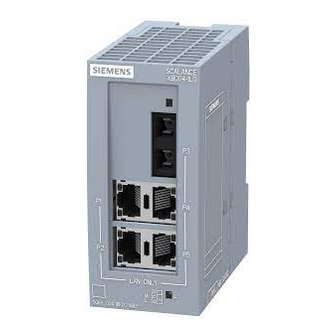
3.2 Product characteristics Product characteristics 3.2.1 SCALANCE XB004-1 Possible attachments The SCALANCE XB004-1 has four RJ-45 jacks and an SC socket for the connection of end devices or other network segments. Figure 3-1 SCALANCE XB004-1 SCALANCE XB-000 Operating Instructions, 12/2015, A2B00077300-06... -
Page 16: Scalance Xb004-2
Description of the device 3.2 Product characteristics 3.2.2 SCALANCE XB004-2 Possible attachments The SCALANCE XB004-2 has four RJ-45 jacks and two SC sockets for the connection of end devices or other network segments. Figure 3-2 SCALANCE XB004-2 SCALANCE XB-000 Operating Instructions, 12/2015, A2B00077300-06... -
Page 17: Scalance Xb004-1Ld
Description of the device 3.2 Product characteristics 3.2.3 SCALANCE XB004-1LD Possible attachments The SCALANCE XB004-1LD has four RJ-45 jacks and an SC socket for the connection of end devices or other network segments. Figure 3-3 SCALANCE XB004-1LD SCALANCE XB-000 Operating Instructions, 12/2015, A2B00077300-06... -
Page 18: Scalance Xb005
Description of the device 3.2 Product characteristics 3.2.4 SCALANCE XB005 Possible connections The SCALANCE XB005 has five RJ-45 jacks for connection of end devices or other network segments. Figure 3-4 SCALANCE XB005 SCALANCE XB-000 Operating Instructions, 12/2015, A2B00077300-06... -
Page 19: Scalance Xb008
Description of the device 3.2 Product characteristics 3.2.5 SCALANCE XB008 Possible connections The SCALANCE XB008 has eight RJ-45 jacks for the connection of end devices or other network segments. Figure 3-5 SCALANCE XB008 SCALANCE XB-000 Operating Instructions, 12/2015, A2B00077300-06... -
Page 20: Scalance Xb004-1G
3.2 Product characteristics 3.2.6 SCALANCE XB004-1G Possible attachments The SCALANCE XB004-1G has four RJ-45 jacks capable of Gigabit and an SC socket for the connection of end devices or other network segments. Figure 3-6 SCALANCE XB004-1G SCALANCE XB-000 Operating Instructions, 12/2015, A2B00077300-06... -
Page 21: Scalance Xb004-1Ldg
3.2 Product characteristics 3.2.7 SCALANCE XB004-1LDG Possible attachments The SCALANCE XB004-1LDG has four RJ-45 jacks capable of Gigabit and an SC socket for the connection of end devices or other network segments. Figure 3-7 SCALANCE XB004-1LDG SCALANCE XB-000 Operating Instructions, 12/2015, A2B00077300-06... -
Page 22: Scalance Xb005G
Description of the device 3.2 Product characteristics 3.2.8 SCALANCE XB005G Possible attachments The SCALANCE XB005G has five RJ-45 jacks capable of Gigabit for connection of end devices or other network segments. Figure 3-8 SCALANCE XB005G SCALANCE XB-000 Operating Instructions, 12/2015, A2B00077300-06... -
Page 23: Scalance Xb008G
Description of the device 3.2 Product characteristics 3.2.9 SCALANCE XB008G Possible attachments The SCALANCE XB008G has eight RJ-45 jacks capable of Gigabit for the connection of end devices or other network segments. Figure 3-9 SCALANCE XB008G SCALANCE XB-000 Operating Instructions, 12/2015, A2B00077300-06... -
Page 24: Tp Ports (Twisted Pair)
3.3 TP ports (twisted pair) TP ports (twisted pair) 3.3.1 Pin assignment With IE switches of the SCALANCE XB-000 product line, the twisted-pair ports are designed as RJ-45 jacks with MDI-X pin assignment (Medium Dependent Interface Autocrossover) of a network component. Pin number... -
Page 25: Functions
Devices not supporting autonegotiation must be set to 1000 Mbps/ half duplex, 100 Mbps/ half duplex or 10 Mbps half duplex. Note The IE switches of the SCALANCE XB-000 product line are plug-and-play devices that require no settings during commissioning. Auto polarity exchange If the pair of receiving cables is connected incorrectly (RD+ and RD- interchanged), the polarity is adapted automatically. -
Page 26: Insulation Between The Tp Ports
Between ports of different port groups, an insulation voltage of 1.5 kV is adhered to (corresponds to IEEE802.3, Chapter 33.4.1.1, Environment B), e.g. between P2 and P3. The requirements for Environment A are met between ports of the same group, e.g. between P2 and P5. SCALANCE XB-000 Operating Instructions, 12/2015, A2B00077300-06... - Page 27 Between ports of different port groups, an insulation voltage of 1.5 kV is adhered to (corresponds to IEEE802.3, Chapter 33.4.1.1, Environment B), e.g. between P2 and P4. The requirements for Environment A are met between ports of the same group, e.g. between P1 and P5. SCALANCE XB-000 Operating Instructions, 12/2015, A2B00077300-06...
-
Page 28: Fo Port (Fiber Optic)
The maximum transmission range (segment length) with a signal attenuation of the fiber- optic cable of ≤ 1 dB/km at 1310 nm is: ● with 62.5/125 µm fiber multimode SIMATIC NET cable: 4 km ● with 50.0/125 µm fiber multimode SIMATIC NET cable: 5 km SCALANCE XB-000 Operating Instructions, 12/2015, A2B00077300-06... -
Page 29: Scalance Xb004-2
≤ 1 dB/km at 1310 nm is: ● with 62.5/125 µm fiber multimode SIMATIC NET cable: 4 km ● with 50.0/125 µm fiber multimode SIMATIC NET cable: 5 km Connectors The cables are connected to SC sockets. SCALANCE XB-000 Operating Instructions, 12/2015, A2B00077300-06... -
Page 30: Scalance Xb004-1Ld
The light source is an "eye safe" class 1 laser with a wavelength of 1310 nm. Range The maximum transmission range (segment length) is 26 km for a signal attenuation of the fiber-optic cable of ≤ 0.5 dB/km. Connectors The cables are connected to SC sockets. SCALANCE XB-000 Operating Instructions, 12/2015, A2B00077300-06... -
Page 31: Scalance Xb004-1G
Depending on the fiber-optic cable used, the maximum transmission range (segment length) is 750 m when using SIMATIC NET fiber-optic multimode cable with SC duplex connectors or 550 m when using a standard multimode FO cable. Connectors The cables are connected to SC sockets. SCALANCE XB-000 Operating Instructions, 12/2015, A2B00077300-06... -
Page 32: Scalance Xb004-1Ldg
The light source is an "eye safe" class 1 laser with a wavelength of 1310 nm. Range The maximum transmission range (segment length) is 10 km for a signal attenuation of the fiber-optic cable of ≤ 0.5 dB/km. Connectors The cables are connected to SC sockets. SCALANCE XB-000 Operating Instructions, 12/2015, A2B00077300-06... -
Page 33: Leds
LED color LED status Meaning Green Link exists, no data reception at port Green Flashing Link exists, data reception at port Green Flashing / flash on and Test phase during power on off in sequence SCALANCE XB-000 Operating Instructions, 12/2015, A2B00077300-06... - Page 34 Description of the device 3.5 LEDs SCALANCE XB-000 Operating Instructions, 12/2015, A2B00077300-06...
-
Page 35: Mounting
The device may only be operated in an environment with pollution degree 1 or 2 (see IEC 60664-1). WARNING When used in hazardous environments corresponding to Class I, Division 2 or Class I, Zone 2, the device must be installed in a cabinet or a suitable enclosure. SCALANCE XB-000 Operating Instructions, 12/2015, A2B00077300-06... -
Page 36: Types Of Installation
Keep to the minimum clearances so that the convection ventilation of the device is not blocked. ● Below at least 10 cm ● Above at least 10 cm See also SIMATIC NET Industrial Ethernet TP and Fiber Optic Networks (http://support.automation.siemens.com/WW/view/en/8763736) SCALANCE XB-000 Operating Instructions, 12/2015, A2B00077300-06... -
Page 37: Fixing Onto Standard Mounting Rails
3. Fit the connectors for the power supply. See also section "Power supply (Page 41)" 4. Insert the terminal block into the sockets on the device. Figure 4-2 SCALANCE XB-000 mounted on the 35 mm DIN rail SCALANCE XB-000 Operating Instructions, 12/2015, A2B00077300-06... - Page 38 3. Lever the catch on the underside of the device approximately 5 mm out using a screwdriver 4. Pull the lower part of the device away from the DIN rail. Figure 4-3 Removal from a 35 mm DIN rail SCALANCE XB-000 Operating Instructions, 12/2015, A2B00077300-06...
-
Page 39: Wall Mounting
"Dimension drawings (Page 73)". 3. Fit the connectors for the power supply. See also section "Power supply (Page 41)". 4. Insert the terminal block into the socket on the device. 5. Screw the device to the wall. SCALANCE XB-000 Operating Instructions, 12/2015, A2B00077300-06... - Page 40 Mounting 4.4 Wall mounting Figure 4-5 Wall mounting of the SCALANCE XB-000 Note The wall mounting must be capable of supporting at least four times the weight of the device. SCALANCE XB-000 Operating Instructions, 12/2015, A2B00077300-06...
-
Page 41: Connecting Up
The power supply is connected via a plug-in terminal block with three terminals on the underside of the SCALANCE XB-000. The functional ground can be connected to the grounded DIN rail. It does not need to be connected for problem-free operation. The power supply is non-floating. -
Page 42: Power Supply 24 Vdc
The following figure shows the position of the power supply and the assignment of the terminal block. Pin number Assignment Pin 1 Functional ground Pin 2 M (chassis ground) Pin 3 L+ (24 VDC) SCALANCE XB-000 Operating Instructions, 12/2015, A2B00077300-06... -
Page 43: Grounding
A functional grounding can be established by connecting a cable from terminal 1 to the DIN rail, , for example. Such a cable should be kept as short as possible. Grounding is, however, not necessary for operation. SCALANCE XB-000 Operating Instructions, 12/2015, A2B00077300-06... -
Page 44: Twisted Pair Cable
Fitting the IE FC RJ45 Plug 180 to the IE FC Standard Cable You will find the notes on installation in the instructions that ship with the IE FC RJ45 Plug 180. Figure 5-1 IE FC 45 Plug 180 SCALANCE XB-000 Operating Instructions, 12/2015, A2B00077300-06... - Page 45 If there is not enough space to release the lock with your hand, you can also use a 2.5 mm screwdriver. You can then remove the IE FC RJ45 Plug 180 from the RJ-45 jack. SCALANCE XB-000 Operating Instructions, 12/2015, A2B00077300-06...
- Page 46 Connecting up 5.4 IE FC RJ-45 Plug 180 SCALANCE XB-000 Operating Instructions, 12/2015, A2B00077300-06...
-
Page 47: Maintenance And Troubleshooting
Possible sources of problems and how to deal with them Fuses The IE switches of the SCALANCE XB-000 product line have a resettable fuse / PTC. If the fuse triggers (all LEDs are off despite correctly applied power supply), the device should be disconnected from the power supply for approximately 30 minutes before turning it on again. - Page 48 Maintenance and troubleshooting 6.1 Possible sources of problems and how to deal with them SCALANCE XB-000 Operating Instructions, 12/2015, A2B00077300-06...
-
Page 49: Technical Specifications
Multimode glass FO cable, cable cross sections 62.5/125 μm and 50/125 μm Permitted cable length (glass FO Cable cross-section Permitted cable length cable) 62.5/125 μm 0 to 4,000 m • • 50/125 μm 0 to 5,000 m • • SCALANCE XB-000 Operating Instructions, 12/2015, A2B00077300-06... - Page 50 MTBF (EN/IEC 61709; 40 °C) 157 years Housing material Polycarbonate (plastic) Weight 165 g Dimensions (W x H x D) 45 x 100 x 87 mm Installation options Mounting on a DIN rail • Wall mounting • SCALANCE XB-000 Operating Instructions, 12/2015, A2B00077300-06...
- Page 51 4 Note The number of IE switches of the SCALANCE XB-000 product line connected in a line influences the frame delay. When a frame passes through IE switches of the SCALANCE XB-000 product line, it is delayed by the store and forward function of the switch •...
-
Page 52: Scalance Xb004-2
19.2 to 28.8 VDC Safety Extra Low Voltage (SELV) Design 3-terminal plug-in block Current consumption Typically 24 VDC 165 mA Effective power loss Typically 24 VDC Overvoltage protection at input PTC resettable fuse (0.5 A / 60 V) SCALANCE XB-000 Operating Instructions, 12/2015, A2B00077300-06... - Page 53 IEEE 802.1Q tags (VLAN ID, priority) transparent forwarding Note The number of IE switches of the SCALANCE XB-000 product line connected in a line influences the frame delay. When a frame passes through IE switches of the SCALANCE XB-000 product line, it is delayed by the store and forward function of the switch •...
-
Page 54: Scalance Xb004-1Ld
Single mode glass FO cable Cable cross-section 10/125 μm Permitted cable length 0 to 26,000 m Attenuation ≤ 0.5 dB/km at 1310 nm 13 dB max. permitted FO cable attenuation with 2 dB link power margin SCALANCE XB-000 Operating Instructions, 12/2015, A2B00077300-06... - Page 55 MTBF (EN/IEC 61709; 40 °C) 176 years Housing material Polycarbonate (plastic) Weight 165 g Dimensions (W x H x D) 45 x 100 x 87 mm Installation options Mounting on a DIN rail • Wall mounting • SCALANCE XB-000 Operating Instructions, 12/2015, A2B00077300-06...
- Page 56 4 Note The number of IE switches of the SCALANCE XB-000 product line connected in a line influences the frame delay. When a frame passes through IE switches of the SCALANCE XB-000 product line, it is delayed by the store and forward function of the switch •...
-
Page 57: Scalance Xb005
During operation ≤ 95 % no condensation Operating altitude During operation ≤ 2,000 m above sea level at max. 56 ℃ ambient temperature ≤ 3,000 m above sea level at max. 50 ℃ ambient temperature SCALANCE XB-000 Operating Instructions, 12/2015, A2B00077300-06... - Page 58 5 Note The number of IE switches of the SCALANCE XB-000 product line connected in a line influences the frame delay. When a frame passes through IE switches of the SCALANCE XB-000 product line, it is delayed by the store and forward function of the switch •...
-
Page 59: Scalance Xb008
During operation ≤ 95 % no condensation Operating altitude During operation ≤ 2,000 m above sea level at max. 56 ℃ ambient temperature ≤ 3,000 m above sea level at max. 50 ℃ ambient temperature SCALANCE XB-000 Operating Instructions, 12/2015, A2B00077300-06... - Page 60 IEEE 802.1Q tags (VLAN ID, priority) transparent forwarding Note The number of IE switches of the SCALANCE XB-000 product line connected in a line influences the frame delay. When a frame passes through IE switches of the SCALANCE XB-000 product line, it is delayed by the store and forward function of the switch •...
-
Page 61: Scalance Xb004-1G
19.2 to 28.8 VDC Safe Extra Low Voltage (SELV) Design 3-terminal plug-in block Current consumption Typical 650 mA Power loss at 24 VDC Typical 15.6 W Overvoltage protection at input PTC resettable fuse (1.0 A / 60 V) SCALANCE XB-000 Operating Instructions, 12/2015, A2B00077300-06... - Page 62 IEEE 802.1Q tags (VLAN ID, priority) transparent forwarding Note The number of IE switches of the SCALANCE XB-000 product line connected in a line influences the frame delay. When a frame passes through IE switches of the SCALANCE XB-000 product line, it is delayed by the store and forward function of the switch •...
-
Page 63: Scalance Xb004-1Ldg
19.2 to 28.8 VDC Safe Extra Low Voltage (SELV) Design 3-terminal plug-in block Current consumption Typical 650 mA Power loss at 24 VDC Typical 15.6 W Overvoltage protection at input PTC resettable fuse (1.0 A / 60 V) SCALANCE XB-000 Operating Instructions, 12/2015, A2B00077300-06... - Page 64 IEEE 802.1Q tags (VLAN ID, priority) transparent forwarding Note The number of IE switches of the SCALANCE XB-000 product line connected in a line influences the frame delay. When a frame passes through IE switches of the SCALANCE XB-000 product line, it is delayed by the store and forward function of the switch •...
-
Page 65: Scalance Xb005G
≤ 2,000 m above sea level at max. 56 ℃ ambient temperature ≤ 3,000 m above sea level at max. 50 ℃ ambient temperature Design, dimensions and weight Immunity EN 61000-6-2 Emission EN 61000-6-4 SCALANCE XB-000 Operating Instructions, 12/2015, A2B00077300-06... - Page 66 IEEE 802.1Q tags (VLAN ID, priority) transparent forwarding Note The number of IE switches of the SCALANCE XB-000 product line connected in a line influences the frame delay. When a frame passes through IE switches of the SCALANCE XB-000 product line, it is delayed by the store and forward function of the switch •...
-
Page 67: Scalance Xb008G
During operation ≤ 95 % no condensation Operating altitude During operation ≤ 2,000 m above sea level at max. 56 ℃ ambient temperature ≤ 3,000 m above sea level at max. 50 ℃ ambient temperature SCALANCE XB-000 Operating Instructions, 12/2015, A2B00077300-06... - Page 68 IEEE 802.1Q tags (VLAN ID, priority) transparent forwarding Note The number of IE switches of the SCALANCE XB-000 product line connected in a line influences the frame delay. When a frame passes through IE switches of the SCALANCE XB-000 product line, it is delayed by the store and forward function of the switch •...
-
Page 69: Approvals
The devices meet the requirements if you keep to the installation instructions and safety- related notices as described here and in the manual "SIMATIC NET Industrial Ethernet Twisted Pair and Fiber Optic Networks (http://support.automation.siemens.com/WW/view/en/8763736)" when installing and operating the device. Notes for the Manufacturers of Machines The devices are not machines in the sense of the EC Machinery Directive. - Page 70 Area". You will find this document • on the data medium that ships with some devices. • on the Internet pages of Siemens Industry Online Support (http://support.automation.siemens.com/WW/view/en). Enter the document identification number C234 as the search term. SIMATIC NET products meet the requirements of the EC directive:94/9/EC "Equipment and Protective Devices for Use in Potentially Explosive Atmospheres".
- Page 71 The product meets the requirements of the AS/NZS 2064 standard (Class A). Marking for the customs union EAC (Eurasian Conformity) Customs union of Russia, Belarus and Kazakhstan Declaration of the conformity according to the technical regulations of the customs union (TR CU) SCALANCE XB-000 Operating Instructions, 12/2015, A2B00077300-06...
- Page 72 1 oct/min, 20 sweeps 1 oct/min, 20 sweeps 2 min/oct, 1 sweep XB004-1G ● ● ● ● ● XB004-1LD ● ● ● ● ● XB005G ● ● ● ● ● XB008G ● ● ● ● ● SCALANCE XB-000 Operating Instructions, 12/2015, A2B00077300-06...
-
Page 73: Dimension Drawings
Dimension drawings Figure 9-1 Dimension drawing, front view (example: SCALANCE XB004-1) SCALANCE XB-000 Operating Instructions, 12/2015, A2B00077300-06... - Page 74 Dimension drawing, side view (example: SCALANCE XB004-1) Note The minimum bending radius of the optical and electrical signal cables used must not be fallen below. Example: SIMATIC NET FO standard cable - bending radius ≥ 70 mm SCALANCE XB-000 Operating Instructions, 12/2015, A2B00077300-06...
-
Page 75: Index
Optical connectors, 49, 52, 54, 61, 63 SCALANCE XB004-1LD, 30 Optical parameters, 49, 52, 54, 61, 63 SCALANCE XB004-1LDG, 32 Order numbers, 49, 52, 54, 57, 59, 61, 63, 65, 67 SCALANCE XB004-2, 29 Further documentation, 5 SCALANCE XB-000 Operating Instructions, 12/2015, A2B00077300-06... - Page 76 Frame delay time, 66 Optical parameters, 61 Order numbers, 65 Order numbers, 61 Permitted ambient conditions, 65 Permitted ambient conditions, 62 Permitted cable lengths, 65 Permitted cable lengths, 61 Switching properties, 66 Switching properties, 62 SCALANCE XB-000 Operating Instructions, 12/2015, A2B00077300-06...
- Page 77 49, 52, 54, 57, 59, 61, 63, 65, 67 SCALANCE XB004-1, 49 SCALANCE XB004-1G, 61 SCALANCE XB004-1LD, 54 SCALANCE XB004-1LDG, 63 SCALANCE XB004-2, 52 SCALANCE XB005, 57 SCALANCE XB005G, 65 SCALANCE XB008, 59 SCALANCE XB008G, 67 Twisted pair cable, 44 SCALANCE XB-000 Operating Instructions, 12/2015, A2B00077300-06...
- Page 78 Index SCALANCE XB-000 Operating Instructions, 12/2015, A2B00077300-06...