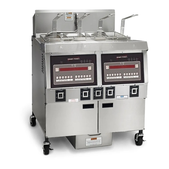
Henny Penny OFE-322 Technical Manual
Cfa electric open fryer
Hide thumbs
Also See for OFE-322:
- Technical manual (115 pages) ,
- Specification sheet (2 pages) ,
- Operator's manual (75 pages)
Table of Contents
Advertisement
Quick Links
Advertisement
Table of Contents
Troubleshooting

Related Manuals for Henny Penny OFE-322


Summary of Contents for Henny Penny OFE-322
- Page 1 Henny Penny CFA Electric Open Fryer Model OFE-321 Model OFE-322 TECHNICAL MANUAL...
-
Page 3: Table Of Contents
Model OFE-321,322 TABLE OF CONTENTS Section Page Section 1. TROUBLESHOOTING ....................1-1 1-1. Introduction ......................1-1 1-2. Safety ........................1-1 1-3. Troubleshooting ......................1-2 1-4. Warnings and Error Messages ................1-5 Section 2. MAINTENANCE ......................2-1 2-1. Introduction ......................2-1 2-2. Maintenance Hints ....................2-1 2-3. Complete Control Panel Replacement ..............2-1 2-4. -
Page 5: Section 1. Troubleshooting
SECTION 1. TROUBLESHOOTING 1-1. INTRODUCTION This section provides troubleshooting information in the form of an easy to read table. If a problem occurs during the first operation of a new fryer, recheck the Installation Section of the Operator’s Manual. Before troubleshooting, always recheck the Operation Section of the Operator’s Manual. -
Page 6: Troubleshooting
1-3. TROUBLESHOOTING To isolate a malfunction, proceed as follows: 1. Clearly define the problem, or symptom and when it occurs. 2. Locate the problem in the troubleshooting table. 3. Review all possible causes, then one at a time, work through the list of corrections until the problem is solved. If maintenance procedures are not followed correctly, injuries and/or property damage could result. - Page 7 1-3. TROUBLESHOOTING(Continued) PROBLEM CAUSE CORRECTION Low or improper Use a meter and check the receptacle Heating of shortening too voltage (elec. unit) voltage against the data plate slow Weak or burnt out Check heating elements per Heating elements (elec.
- Page 8 1-3. TROUBLESHOOTING (Continued) PROBLEM CAUSE CORRECTION Drain valve clogged Open valve, force cleaning brush through Shortening will not drain from frypot with crumbs drain Drain valve will not Replace cotter pins in valve coupling open by turning handle ...
-
Page 9: Warnings And Error Messages
1-4. WARNINGS AND The controls monitor procedure problems and system failures ERROR MESSAGES with warnings and error codes. The display shows the warning or error code, and an alarm sounds. Pressing cancels most warnings and pressing any control button stops most error code alarms. But there are some exceptions (see below). - Page 10 1-4. WARNINGS AND ERROR MESSAGES (Continued) ERROR CODES DISPLAY CAUSE CORRECTION “E-4” PC board too hot Check ventilation louvers on side of fryer “CPU TOO for obstructions; if louvers are clear, HOT” have PC board checked “E-5” Controls sensing 405°F Have heat components and temperature “FRYER TOO or above...
-
Page 11: Error Codes
3-5. WARNINGS AND ERROR MESSAGES (Continued) ERROR CODES DISPLAY CAUSE CORRECTION “E-41” Memory scrambled; an individual Turn the POWER switch off and back “SYSTEM product program may be scrambled: on; if error code persists, have the DATA LOST” Ex: “E-41 -2- DATA LOST”; this PC board checked or re-initialized means product #2 program is scrambled... -
Page 12: Section 2. Maintenance
SECTION 2. MAINTENANCE 2-1. INTRODUCTION This section provides procedures for the checkout and replacement of the various parts used within the fryer. Before replacing any parts, refer to the Troubleshooting Section. It will aid you in determining the cause of the malfunction. 2-2. -
Page 13: Power Switch
2-4. POWER SWITCH 1. Remove electrical power supplied to fryer. To avoid electrical shock or property damage, move the POWER switch to OFF and disconnect main circuit breaker, or unplug cord at wall receptacle. 2. Remove control panel. 3. Label and remove the wires from the switch. With test instrument, check across the terminals of the switch with the switch in the ON position, then in the OFF position. -
Page 14: I/O Power Supply Boards Assembly
2-6. I/O POWER SUPPLY BOARD ASSEMBLY The input/output power supply board assembly distributes voltage to the various components in the fryer. The board also receives information from components in the fryer. 1. Remove electrical power supplied to the unit. To avoid electrical shock or property damage, move the POWER switch to OFF and disconnect main circuit breaker, or unplug cord at wall receptacle. -
Page 15: Filter Switch
2-7. DRAIN MICROSWITCH (Continued) 2. The following check should be made to determine if the drain microswitch is defective. a. Remove the two screws securing the microswitch to the drain rod valve bracket. b. Remove wires from the switch. c. Check for continuity across the two outside terminals of the drain switch. -
Page 16: Heating Elements
2-9. HEATING ELEMENTS Heating elements are available for 208, 480 and 230 volts. Check data plate to determine correct voltage. Checkout: If the shortenings temperature recovery is very slow or at a slower rate than required, this may indicate defective heating element(s). An ohmmeter will quickly indicate if the elements are shorted or open. - Page 17 2-9. HEATING ELEMENTS (Continued) 3. Remove the heating element wires from the terminals by removing the nuts and washers. Label each so it can be replaced on the new element in the same position. 4. Remove the bolts from the five element spreaders. The element spreaders will now pull off the elements.
- Page 18 2-9. HEATING ELEMENTS (Continued) 13. Connect the power cord to the wall receptacle or close wall circuit breaker. Heating elements should never be energized without shortening in the frypot, or damage to the elements could result. 14. Replace the shortening in the frypot. Fig.
- Page 19 2-10. HEATING CONTACTORS Each well of an electric fryer requires two switching contactors. The first in line is the primary contactor and the second in line is the heat contactor. When open, the primary contactor does not allow power to flow to the heat contactor. When closed, the primary supplies voltage to the heat contactor.
- Page 20 2-10. HEATING Checkout (Power Supplied) CONTACTORS (Continued) To avoid electrical shock, make connections before applying power, take reading, and remove power before removing meter leads. The following checks are performed with the wall circuit breaker closed and the main power switch in the ON position. 1.
-
Page 21: Heating Contactors
2-10. HEATING Checkout (Power Supplied) Electromechanical Contactor Replacement: CONTACTORS If either contactor is defective it must be replaced as follows: (Continued) To avoid electrical shock or property damage, move the POWER switch to OFF and disconnect main circuit breaker, or unplug cord at wall receptacle, to the frypot to be worked on. -
Page 22: High Temperature Limit Control
2-12. HIGH TEMPERATURE LIMIT CONTROL The electric units, models OFE-321/2/3/4, use the same high temperature control limits as the gas units, but the mounting of the capillary tube is different on the electric units compared to the gas units. Checkout: Use the same procedure as in the High Limit Temperature Control (Gas) Section. - Page 23 9. Insert new 425 degree high limit, part no. 60241 and 2-12. HIGH TEMPERATURE replace screws. LIMIT CONTROL 2-11 (Continued) 10. Uncoil capillary tube, starting at control, and insert through pot fitting. To avoid electrical shock or other injury, run the capillary line under and away from all electrical power wires and terminals.
- Page 24 2-13...
- Page 25 2-14...
- Page 26 2-15...
-
Page 27: Section 3. Parts Information
This section lists the replaceable parts of the Henny Penny OFE-321 & 322 Open Fryers. 3-2. GENUINE PARTS Use only genuine Henny Penny parts in your fryer. Using a part of lesser quality or substitute design may result in damage to the unit or personal injury. - Page 28 Figure 3-1. Electric Heat Controls...
- Page 29 8 CONTACTOR – E/M (SN: BA08010020 & AFTER) 65073 60810 I/O BOARD TO CONTROL CABLE - 4 PIN 60838 TRANSFORMER -480V TO 240V - OFE-322 60847 TRANSFORMER MOUNTING BRACKET 19923 TRANSFORMER-LARGE--480V-240V - OFE-321 13* BLOCK – 60 AMP FUSE (208-240V FRYERS) 60722 ...
- Page 30 Figure 3-2. Side, Top, & Rear Panels...
- Page 31 FIGURE & PART NO. DESCRIPTION QTY. PER UNIT ITEM NO. 321 322 SIDE, TOP, AND REAR PANELS TUBE, OIL RETURN LINE – OFE-322 26901 (before 12-1-06) TUBE, OIL RETURN LINE – OFE-322 73957 (after 12-1-06) – OFE-322 FP01-082 CONNECTOR - 3/8 TUBE TO ½ NPT SS –...
- Page 32 Figure 3-3. Oil Filtering System...
- Page 33 FIGURE & PART NO. DESCRIPTION QTY. PER UNIT ITEM NO. 321 322 OIL FILTERING SYSTEM 66005 FRONT PLATE 17320 PIPE, FRONT 55152 DRAIN VALVE & COUPLING ASSY. 60736 DRAIN VALVE EXT. (ELECT.) (SN: GM024JB & BELOW) 24643 DRAIN VALVE EXT. (ELECT.) (SN: GM025JB &...
- Page 34 Figure 3-4. Door, Switches, Menu Card, & Control Board 1005...
- Page 35 10 72277 POWER SWITCH ASSY. 11 18227 DRAIN MICROSWITCH KIT – OFE-321 N/O DRAIN SWITCH-CONVERSION 14681 KIT – OFE-322 N/O DRAIN SWITCH-CONVERSION 14651 NS02-005 18818 DRAIN VALVE EXTENSION ROD ROD – N/O 320 DRAIN 74193 SC01-058 SCREWS, COVER & BRACKET RETAINING (6-32 X 1.5 IN.)
- Page 36 Figure 3-5. Baskets and Return Faucet 3-10...
- Page 37 FIGURE & PART NO. DESCRIPTION QTY. PER UNIT ITEM NO. 321 322 BASKETS AND RETURN FAUCET 26873 FRYPOT COVER 21033 HALF SIZE BASKET HALF SIZE BASKET – FRONT & REAR HOOK 69085 FP01-087 ELBOW, MALE, 3/8 IN. 17333 FEMALE DISCONNECT 17334 MALE DISCONNECT 70560...
- Page 38 Figure 3-6. Shrouds and Pot & Counter Top 3-12...
- Page 39 60340 BRACKET, REAR SHROUD 63700 REAR SHROUD ASSY. 26870 REAR SHROUD ASSY. 24899 POT & COUNTERTOP ASSY. (OFE-321) 24896 POT & COUNTERTOP ASSY. (OFE-322) 60322 SHROUD CONTROL VERTICAL RH 60328 SHROUD CONTROL UPPER MIDDLE SC04-003 SCREW 60326 SHROUD CONTROL DIVIDER...
- Page 40 Figure 3-7. Electric Heater 3-14...
- Page 41 FIGURE & PART NO. DESCRIPTION QTY. PER UNIT ITEM NO. 321 322 ELECTRIC HEATER 1 HEATING ELEMENT – 208V 7333W 30292-2 1 HEATING ELEMENT – 240V 7333W 30292-6 1 HEATING ELEMENT – 480V 7333W 30292-1 26917 FRY BASKET SUPPORT 95349 ASSY-HI LIMIT HLDR/SPDR LH 95182...
- Page 42 Figure 3-8. Drain Pan, Screen, and Cover 3-16 1005...
- Page 43 FIGURE & PART NO. DESCRIPTION QTY. PER UNIT ITEM NO. 321 322 DRAIN PAN, SCREEN, & COVER KIT – 32X SS FILTER SCREEN ASSY (INCLUDES #8) 14671 65211 CRUMB CATCHER 65447 BOTTOM FILTER SCREEN 17505 FILTER ENVELOPE CLIPS 69118 ASSY-32X SS FILTER SCREEN PIPE ...
- Page 44 Figure 3-9. Autolift Feature 3-18...
- Page 45 FIGURE &. PART NO. DESCRIPTION QTY. PER UNIT ITEM NO. 3-12 AUTOLIFT FEATURE 50814 FRYPOT COVER, AUTOLIFT 50750 FILTER VALVE, OIL RETURN 3 50764 MICROSWITCH, RIGID LEVER 4 50716 ACTUATOR, AUTOLIFT, 24V MOTOR (SN: EN040JB) & BELOW) 4 63602 ACTUATOR, AUTOLIFT, 24V MOTOR (SN: EN041JB UP TO BP0812001)