Henny Penny OFE-322 Technical Manual
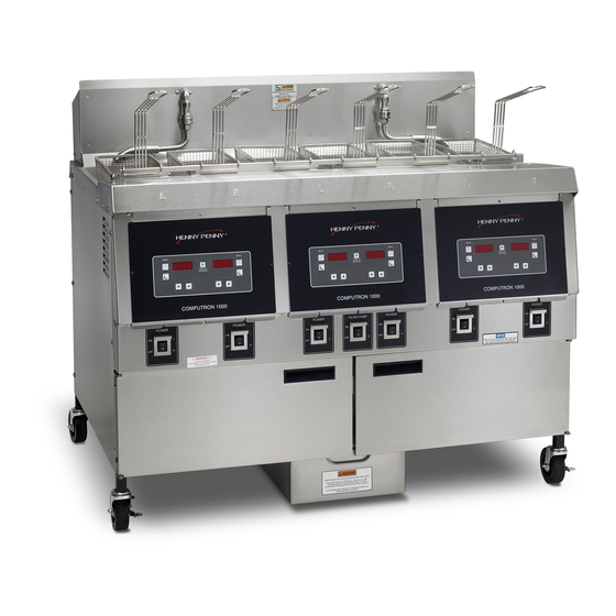
Open fryer
Hide thumbs
Also See for OFE-322:
- Technical manual (45 pages) ,
- Specification sheet (2 pages) ,
- Operator's manual (75 pages)

Related Manuals for Henny Penny OFE-322


Summary of Contents for Henny Penny OFE-322
- Page 1 Henny Penny Open Fry Station Model OFE/OFG-323 Model OFE/OFG-322 Model OFE/OFG-321 Model OFE/OFG-324 Model OEA/OGA-323 Model OEA/OGA-322 Model OEA/OGA-321 Model OEA/OGA-324 Model ODE/ODG-323 TECHNICAL MANUAL...
- Page 2 Model OFE/OFG-321,322,323,324 This manual should be retained in a convenient location for future reference. A wiring diagram for this appliance is located on the inside of the right side panel. Post in a prominent location, instructions to be followed in event user smells gas. This information shall be obtained by consulting the local gas supplier.
-
Page 3: Table Of Contents
Model OFE/OFG-321,322,323,324 TABLE OF CONTENTS Section Page Section 1. TROUBLESHOOTING ....................1-1 1-1. Introduction ......................1-1 1-2. Safety ........................1-1 1-3. Troubleshooting ......................1-2 1-4. Error Codes ......................1-5 Section 2. MAINTENANCE ......................2-1 2-1. Introduction ......................2-1 2-2. Maintenance Hints ....................2-1 2-3. High Temperature Limit Control (Gas Units) ............2-1 2-4. -
Page 4: Section 1. Troubleshooting
Model OFE/OFG-321,322,323,324 SECTION 1. TROUBLESHOOTING 1-1. INTRODUCTION This section provides troubleshooting information in the form of an easy to read table. If a problem occurs during the first operation of a new fryer, recheck the Installation Section of the Operator’s Manual. Before troubleshooting, always recheck the Operation Section of the Operator’s Manual. -
Page 5: Troubleshooting
Model OFE/OFG-321,322,323,324 1-3. TROUBLESHOOTING To isolate a malfunction, proceed as follows: 1. Clearly define the problem, or symptom and when it occurs. 2. Locate the problem in the troubleshooting table. 3. Review all possible causes, then one at a time, work through the list of corrections until the problem is solved. - Page 6 Model OFE/OFG-321,322,323,324 1-3. TROUBLESHOOTING(Continued) PROBLEM CAUSE CORRECTION Low or improper Use a meter and check the receptacle Heating of shortening too voltage (elec. unit) voltage against the data plate slow Weak or burnt out Check heating elements per Heating elements (elec.
- Page 7 Model OFE/OFG-321,322,323,324 1-3. TROUBLESHOOTING (Continued) PROBLEM CAUSE CORRECTION Drain valve clogged Open valve, force cleaning brush through Shortening will not drain from frypot with crumbs drain Drain valve will not Replace cotter pins in valve coupling open by turning handle ...
-
Page 8: Error Codes
Model OFE/OFG-321,322,323,324 1-4. ERROR CODES In the event of a control system failure, the digital display shows an error message. These messages are coded: “E-4”, “E-5”, “E- 6A”, “E-6B”, “E-10”, “E-15”, “E-20”, “E-31”, “E-41”, “E-46”, and “E-92”. A constant tone is heard when an error code is displayed, and to silence this tone, press any button. - Page 9 Model OFE/OFG-321,322,323,324 1-4. ERROR CODES (Continued) DISPLAY CAUSE PANEL BOARD CORRECTION “E-20A” Vacuum Press the timer button to try the ignition process again, and if “E-20A” persists, check the air switch per Vacuum switch failure (stuck closed) Switch Section “E-20B” Draft fan or Press the timer button to try the ignition process again, and if “E-20B”...
-
Page 10: Section 2. Maintenance
Model OFE/OFG-321,322,323,324 SECTION 2. MAINTENANCE 2-1. INTRODUCTION This section provides procedures for the checkout and replacement of the various parts used within the fryer. Before replacing any parts, refer to the Troubleshooting Section. It will aid you in determining the cause of the malfunction. 2-2. - Page 11 Model OFE/OFG-321,322,323,324 2-3 HIGH TEMPERATURE LIMIT CONTROL (Continued) 3. Remove the two nuts securing the high limit bracket to the unit and pull the bracket from the unit. 4. Remove the two screws securing the high limit to the bracket, and remove the high limit from the bracket.
- Page 12 Model OFE/OFG-321,322,323,324 2-3 HIGH TEMPERATURE LIMIT CONTROL (Continued) 5. Remove the bracket from the heat tube covering the high limit bulb. 6. Straighten the capillary tube behind the pot wall. 7. Pull the high limit bulb through the retainers on the heat tube. 8.
-
Page 13: Complete Control Panel Replacement
Model OFE/OFG-321,322,323,324 2-4. COMPLETE CONTROL PANEL REPLACEMENT Should the control board become inoperative, follow these instructions for replacing the board. 1. Remove electrical power supplied to the unit. To avoid electrical shock or property damage, move the POWER switch to OFF and disconnect main circuit breaker, or unplug cord at wall receptacle. -
Page 14: Temperature Probe Replacement
Model OFE/OFG-321,322,323,324 2-5. POWER SWITCH (Continued) 4. With control panel removed, and the wires off the switch, push in on tabs on the switch to remove from panel. 5. Replace with new switch, and reconnect wires to switch. 6. Replace the control panel. 2-6. - Page 15 Model OFE/OFG-321,322,323,324 2-6. TEMPERATURE PROBE REPLACEMENT ELECTRIC (Continued)
- Page 16 Model OFE/OFG-321,322,323,324 2-6. TEMPERATURE PROBE 7. Tighten the compression nut hand tight and then a half turn REPLACEMENT with wrench. (Continued) Excess force will damage temperature probe. 8. Connect new temperature probe to PC board and replace control panel. 9. Replace shortening. 10.
-
Page 17: Flame Sensor (Gas Units)
Model OFE/OFG-321,322,323,324 2-7. FLAME SENSOR The flame sensor recognizes the pilot flame and allows gas to (Gas Units) continue to the pilot. The flame sensor must send a minimum of two (2) micro amps to the ignition module. The pilot flame should be split in two by the flame sensor, causing the flame sensor to be bright red in color. -
Page 18: Pilot/Ignitor Assembly
Model OFE/OFG-321,322,323,324 2-8. PILOT / IGNITOR The Henny Penny open fryer (gas) has electronic spark ignition ASSEMBLY that lights a standing pilot. The gap between the spark electrode and the pilot hood should be set at 1/8 of an inch. -
Page 19: Ignitor Module
Model OFE/OFG-321,322,323,324 2-9. IGNITOR MODULE During normal operation, the ignition modules send 24 volts to the ignitors and gas control valve. If a module does not sense a pilot flame, the module starts the ignition process again. But, if a pilot light goes out for longer that 10 seconds, or it goes out 3 times within 10 seconds, the module keeps the 24 volts from reaching the gas control valve. -
Page 20: I/O Power Supply Boards Assembly
Model OFE/OFG-321,322,323,324 2-11. I/O POWER SUPPLY BOARD ASSEMBLY The input/output power supply board assembly distributes voltage to the various components in the fryer. The board also receives information from components in the fryer. 1. Remove electrical power supplied to the unit. To avoid electrical shock or property damage, move the POWER switch to OFF and disconnect main circuit breaker, or unplug cord at wall receptacle. -
Page 21: Speaker Assembly (Gas Units)
Model OFE/OFG-321,322,323,324 2-12. VACUUM SWITCH (Continued) 5. Using a Phillips head screwdriver, remove the screws securing the vacuum switch to the shroud. 6. Install the new vacuum switch in reverse order. To avoid property damage, do not tamper with, or disas- semble this component. -
Page 22: Drain Microswitch
Model OFE/OFG-321,322,323,324 2-14. DRAIN MICROSWITCH Upon turning the drain handle, the drain microswitch circuit should open, cutting off the pilot flame. This will prevent the fryer from heating while shortening is being drained from the frypot. 1. Remove electrical power supplied to the unit. To avoid electrical shock or property damage, move the POWER switch to OFF and disconnect main circuit breaker, or unplug cord at wall receptacle. -
Page 23: Gas Control Valve Assembly
Model OFE/OFG-321,322,323,324 2-15. FILTER SWITCH (Continued) 2. Remove the control panel above the switch. 3. Label and remove the wires from the switch. With test instrument, check across the terminals of the switch with the switch in the ON position, and then in the OFF position. With the switch in the ON position, the circuit should be closed. - Page 24 Model OFE/OFG-321,322,323,324 2-16. GAS CONTROL VALVE ASSEMBLY (Continued) 3. Using a 7/16 inch wrench, remove the pilot line from the gas control valve. 4. Using a 1 inch wrench, loosen the nut securing the main gas inlet line to the gas control valve. 5.
-
Page 25: Blower Motor Assembly
Model OFE/OFG-321,322,323,324 2-16. GAS CONTROL VALVE ASSEMBLY (Continued) 7. With the bracket dropped down, remove the two screws behind the bracket securing the gas control valve to the bracket. 8. Install the new gas control valve in reverse order. 2-17. BLOWER MOTOR ASSEMBLY The blower motor assembly induces the draft for the burners. - Page 26 Model OFE/OFG-321,322,323,324 2-17. BLOWER MOTOR ASSEMBLY (Continued) 4. Remove wire nuts connecting blower motor wires to wires in conduit. 5. Loosen conduit from blower motor. 6. Remove screws connecting flue to bracket in upper frame. 7. Remove screws connecting flue to blower. 2-17...
-
Page 27: Heating Elements (Electric Only)
Model OFE/OFG-321,322,323,324 2-17. BLOWER MOTOR ASSEMBLY (Continued) 8. Using 3/8 inch nut driver, remove nuts securing blower to the unit. Pull blower from unit. 9. Install new blower in reverse order. 2-18. HEATING ELEMENTS (ELECTRIC ONLY) Heating elements are available for 208 and 230 volts. Check data plate to determine correct voltage. - Page 28 Model OFE/OFG-321,322,323,324 2-18. HEATING ELEMENTS (ELECTRIC ONLY) (Continued) 3. Perform an ohm check on one element at a time, with wires disconnected from element. If the resistance is not within tolerance, replace the element. Voltage Wattage Resistance Ohms (cold) 4800 4800 Replacement: Refer to figure 2-2.
- Page 29 Model OFE/OFG-321,322,323,324 2-18. HEATING ELEMENTS (ELECTRIC ONLY) (Continued) 9. Evenly space the element spreaders on the sides of the elements and reinstall bolts. Place the fifth spreader in the front of the elements as to protect the temperature probe. (Fig.6-1 10.
-
Page 30: Heating Contactors (Electric Only)
Model OFE/OFG-321,322,323,324 2-19. HEATING CONTACTORS (ELECTRIC ONLY) Each well of an electric fryer requires two switching contactors. The first in line is the primary contactor and the second in line is the heat contactor. When open, the primary contactor does not allow power to flow to the heat contactor. - Page 31 Model OFE/OFG-321,322,323,324 2-19. HEATING Checkout (Power Supplied) CONTACTORS (ELECTRIC ONLY) (Continued) To avoid electrical shock, make connections before applying power, take reading, and remove power before removing meter leads. The following checks are performed with the wall circuit breaker closed and the main power switch in the ON position.
-
Page 32: Speaker Assembly (Electric Units)
Model OFE/OFG-321,322,323,324 2-19. HEATING Checkout (Power Supplied) CONTACTORS Electromechanical Contactor Replacement: (ELECTRIC ONLY) If either contactor is defective it must be replaced as follows: (Continued) To avoid electrical shock or property damage, move the POWER switch to OFF and disconnect main circuit breaker, or unplug cord at wall receptacle, to the frypot to be worked on. -
Page 33: High Temperature Limit Control (Electric Units)
Model OFE/OFG-321,322,323,324 2-21. HIGH TEMPERATURE LIMIT CONTROL The electric units, model OFE-321/2/3/4, use the same high (Electric Units) temperature control limits as the gas units, OFG-321/2/3/4, but the mounting of the capillary tube is different on the electric units compared to the gas units. Checkout: Use the same procedure as in the High Limit Temperature Control (Gas) Section. -
Page 34: Autolift Actuator (Motor) Replacement (If Applicable)
Model OFE/OFG-321,322,323,324 2-21. HIGH TEMPERATURE 10. Uncoil capillary tube, starting at control, and insert through LIMIT CONTROL pot fitting. (Electric Units) (Continued) To avoid electrical shock or other injury, run the capillary line under and away from all electrical power wires and terminals. - Page 35 Model OFE/OFG-321,322,323,324 2-22. AUTOLIFT ACTUATOR (MOTOR) REPLACEMENT(if applicable) (Continued) 4. Remove rear cover. CUT WIRES HERE 5. Disconnect actuator connector and cut the wires from the other half of the connector, as shown at left. The new actuator wires do not have a connector on them and must be connected directly to the wires on the unit.
- Page 36 Model OFE/OFG-321,322,323,324 2-22. AUTOLIFT ACTUATOR (MOTOR) REPLACEMENT (if applicable) (Continued) 9. Remove the 2 front mounting screws from the actuator support plate. 10. Remove all the top screws, securing all the actuator support plates to the back shroud, to help loosen the back shroud. 11.
-
Page 37: Autolift Transformer Replacement (If Applicable)
Model OFE/OFG-321,322,323,324 2-23. AUTOLIFT 1. Remove electrical power supplied to unit. TRANSFORMER REPLACEMENT (if applicable) To avoid electrical shock or property damage, move the power switch to OFF and disconnect main circuit breaker, or unplug cord at wall receptacle. 2. Remove control panel. 3. - Page 38 Model OFE/OFG-321,322,323,324 2-24. AUTOLIFT PC BOARD REPLACEMENT (if applicable) (Continued) 4. Using a Phillips-head screwdriver, remove the 2 screws securing the autolift PC board bracket to the frame and remove bracket from unit. (The right screw needs removed to disconnect the ground wire, but the left screw can be loosened and the bracket slid forward to be removed through the slots.) 5.
- Page 39 Model OFE/OFG-321,322,323,324 120 Volt 2-30...
- Page 40 Model OFE/OFG-321,322,323,324 208/240 Volt (Domestic) 2-31...
- Page 41 Model OFE/OFG-321,322,323,324 Drain Switch wired N/O 2-32 1104...
- Page 42 Model OFE/OFG-321,322,323,324 Drain Switch wired N/O – SN: HN048JC & Above – Robertshaw Module 2-33...
- Page 43 Model OFE/OFG-321,322,323,324 Fenwal Module 2-34...
- Page 44 Model OFE/OFG-321,322,323,324 Drain Switch wired N/O 2-35...
- Page 45 Model OFE/OFG-321,322,323,324 2-36...
- Page 46 Model OFE/OFG-321,322,323,324 Drain Switch wired N/O 2-37...
- Page 47 Model OFE/OFG-321,322,323,324 Drain Switch wired N/O 2-38...
- Page 48 Model OFE/OFG-321,322,323,324 Drain Switch wired N/O – SN: HN048JC & Above – Robertshaw Module 2-39...
- Page 49 Model OFE/OFG-321,322,323,324 Fenwal Module 2-40...
- Page 50 Model OFE/OFG-321,322,323,324 Drain Switch wired N/O 2-41...
- Page 51 Model OFE/OFG-321,322,323,324 Drain Switch wired N/O – SN: HN048JC & Above 2-42...
- Page 52 Model OFE/OFG-321,322,323,324 1104 2-43...
- Page 53 Model OFE/OFG-321,322,323,324 Drain Switch wired N/O 2-44 1102...
- Page 54 Model OFE/OFG-321,322,323,324 Drain Switch wired N/O 2-45...
- Page 55 Model OFE/OFG-321,322,323,324 Drain Switch wired N/O 2-46...
- Page 56 Model OFE/OFG-321,322,323,324 Drain Switch wired N/O 2-47...
- Page 57 Model OFE/OFG-321,322,323,324 Drain Switch wired N/O 2-48...
- Page 58 Model OFE/OFG-321,322,323,324 Drain Switch wired N/O – SN: HN048JC & Above 2-49...
- Page 59 Model OFE/OFG-321,322,323,324 Drain Switch wired N/O – SN: HN048JC & Above – Robertshaw Module 2-50...
- Page 60 Model OFE/OFG-321,322,323,324 Fenwal Module 2-51...
- Page 61 Model OFE/OFG-321,322,323,324 Drain Switch wired N/O – Robertshaw Module 2-52...
- Page 62 Model OFE/OFG-321,322,323,324 Fenwal Module 2-53...
-
Page 63: Wiring Diagrams
Model OFE/OFG-321,322,323,324 Computron 1000 Wiring Diagrams OFE-32X – SN: BA0804018 & above OFG-32X – SN: BN0804044 & above 2-54... - Page 64 Model OFE/OFG-321,322,323,324 2-55...
- Page 65 Model OFE/OFG-321,322,323,324 2-56...
- Page 66 Model OFE/OFG-321,322,323,324 2-57...
- Page 67 Model OFE/OFG-321,322,323,324 2-58...
- Page 68 Model OFE/OFG-321,322,323,324 2-59...
- Page 69 Model OFE/OFG-321,322,323,324 Computron 8000 Split-Vat Wiring Diagrams 2-60...
- Page 70 Model OFE/OFG-321,322,323,324 2-61...
- Page 71 Model OFE/OFG-321,322,323,324 2-62...
- Page 72 Model OFE/OFG-321,322,323,324 2-63...
- Page 73 Model OFE/OFG-321,322,323,324 2-64...
- Page 74 Model OFE/OFG-321,322,323,324...
- Page 75 During this time, any frypot that fails due to manufacturing or workmanship issues will be replaced at no charge for parts, labor, or freight. Henny Penny will either install a new frypot at no cost or provide a new or reconditioned replacement fryer at no cost.
-
Page 76: Section 3. Parts Information
This section lists the replaceable parts of the Henny Penny OFE/OFG- 32x Open Fryers. 3-2. GENUINE PARTS Use only genuine Henny Penny parts in your fryer. Using a part of lesser quality or substitute design may result in damage to the unit or personal injury. - Page 77 Model OFE/OFG-321,322,323,324 Gas Heat 1107...
- Page 78 Model OFE/OFG-321,322,323,324 QTY. PER UNIT ITEM NO. PART NO. DESCRIPTION GAS HEAT 14936 KIT - IGNITION MODULE- CE (SN:BN0712013 & BELOW) 77602 IGNITION MODULE- CE (SN:BN0712014 & ABOVE) 14935 KIT-IGNITION MDL-NON-CE (SN:BN0803028 & BELOW) 77839 IGNITION MDL- NON-CE (SN:BN0803029 & ABOVE) ...
- Page 79 Model OFE/OFG-321,322,323,324 Electric Heat Controls...
- Page 80 Model OFE/OFG-321,322,323,324 PART NO. DESCRIPTION QTY. PER UNIT ITEM NO. 321 322 323 ELECTRIC HEAT CONTROLS 1 54561 SPEAKER ASSY. 1 26863 SPEAKER ASSY. (CFA ONLY) 60781 SPEAKER BRACKET ASSY. (ELEC. ONLY) 24916 SPEAKER BRACKET ASSY. (CFA ONLY) ...
- Page 81 Model OFE/OFG-321,322,323,324 Side, Top, & Rear Panels...
- Page 82 Model OFE/OFG-321,322,323,324 PART NO. DESCRIPTION QTY PER UNIT ITEM NO. 321 322 323 SIDE, TOP, AND REAR PANELS KIT – OFG322 - 3/8 TO 5/8 RETURN RETROFIT 14854 KIT – OFE322 - 3/8 TO 5/8 RETURN RETROFIT 14856 KIT – OFG324 - 3/8 TO 5/8 RETURN RETROFIT 14860 KIT –...
- Page 83 Model OFE/OFG-321,322,323,324 Gas Heat Ducting & Insulation...
- Page 84 Model OFE/OFG-321,322,323,324 PART NO. DESCRIPTION QTY. PER UNIT ITEM NO. 321 322 323 GAS HEAT DUCTING & INSULATION 60181 INSULATION, LH DUCT, FRONT & REAR 60180 INSULATION, LH DUCT, TOP & BOTTOM 60387 LH SIDE FLUE DUCT ASSY. 60182 INSULATION, LH DUCT, DIVIDER NS02-002 NUT, LH DUCT RETAINING 60159...
- Page 85 Model OFE/OFG-321,322,323,324 Oil Filtering System 3-10...
- Page 86 Model OFE/OFG-321,322,323,324 PART NO. DESCRIPTION QTY. PER UNIT ITEM NO. 321 322 323 OIL FILTERING SYSTEM 66005 FRONT PLATE 17320 PIPE, FRONT 55152 DRAIN VALVE & COUPLING ASSY. 60388 DRAIN VALVE EXTENSION (GAS) (321, (SN: BN022JB & BELOW; 322 & 323, SN: GN045JB &...
- Page 87 Model OFE/OFG-321,322,323,324 Assy- Pump Motor/Tubing-OFG321 PART NO. DESCRIPTION QTY. PER UNIT ITEM NO. 60442 ASSY-TUBE FILTER TO PUMP 24257 ASSY-TUBE PUMP TO POT OFG321 17407 CONNCETOR ½ MALE ELBOW 3-12...
- Page 88 Model OFE/OFG-321,322,323,324 Assy-Pump Motor/Tubing 322-323 PART NO. DESCRIPTION QTY. PER UNIT ITEM NO. 322 323 60293 TUBE-OIL RETURN LINE FP01-082 CONNECTOR - 3/8 TUBE TO ½ NPT SS 17407 ELBOW, FILTER PUMP TUBE 60442 ASSY-TUBE FILTER TO PUMP 3-13...
- Page 89 Model OFE/OFG-321,322,323,324 Oil Filtering System PART NO. DESCRIPTION QTY. PER UNIT ITEM NO. √1 67583 MOTOR, 1/2 HP - 50/60 Hz √2 17476 SEAL KIT √3 17437 PUMP ASSEMBLY √4 SC01-132 SCREW, Pump Cover √5 17451 COVER, Pump √6 17447 ROTOR, Pump √7 17446...
- Page 90 BA0604011 & Above OEA-321-SN: BB0604002 & Below BB0604003 & Above OFG-322-SN: BN0604004 & Below BN0604005 & Above OGA-322-SN: BP0605006 & Below BP0605007 & Above OFE-322-SN: BA0604001 & Below BA0604002 & Above OEA-322-SN: OFG-323-SN: BN0604014 & Below BN0604015 & Above OGA-323-SN: OFE-323-SN: OEA-323-SN: Door, Switches, Menu Card, &...
- Page 91 COVERED POWER SWITCH (CE) KIT – OFE-321 N/O DRAIN SWITCH 14681 KIT – OFG-321 N/O DRAIN SWITCH 14682 KIT – OFG-322 & 323 N/O DRAIN SWITCH 14650 KIT – OFE-322 & 323 N/O DRAIN SWITCH 14651 18227 DRAIN MICROSWITCH NS02-005 59224...
- Page 92 Model OFE/OFG-321,322,323,324 71880 LEFT DOOR ASSY. (3 WELL) 71875 LEFT DOOR ASSY. (2 WELL) 71870 DOOR ASSY. (1 WELL) HINGE – DOOR – TOP 17618 HINGE – DOOR – BOTTOM 17620 59565 GM MENU CARD 61724 CFA MENU CARD 59566 BLANK MENU CARD 69227 MENU CARD - POLLO...
- Page 93 Model OFE/OFG-321,322,323,324 CE Gas Valve Assembly Standard Gas Valve Assembly 3-18...
- Page 94 Model OFE/OFG-321,322,323,324 PART NO. DESCRIPTION QTY. PER UNIT ITEM NO. 321 322 323 GAS VALVE ASSEMBLIES VALVE – SOLENOID-24V - 50-60 HZ 34802 66006 WELD ASSY-GAS VALVE BRKT (SN: BN0901008 & BELOW) 80985 WELD ASSY-GAS VALVE BRKT (SN: BN0901009 & ABOVE) WELD ASSY –...
- Page 95 Model OFE/OFG-321,322,323,324 Baskets and Return Faucet 3-20...
- Page 96 Model OFE/OFG-321,322,323,324 PART NO. DESCRIPTION QTY. PER UNIT ITEM NO. 321 322 323 BASKETS AND RETURN FAUCET 60843 FRYPOT COVER WELD ASSY – SPLIT POT COVER 78264 1 PER VAT 26873 FRYPOT COVER (CFA ONLY) 65466 HALF SIZE BASKET, COATED-BLACK 81814 HALF SIZE BASKET, COATED-RED 21033...
- Page 97 Model OFE/OFG-321,322,323,324 Shrouds and Pot & Counter Top 3-22...
- Page 98 REAR SHROUD ASSY. – FFS - 323 78742-007 REAR SHROUD ASSY. – FFF - 323 78742-008 24797 POT & COUNTERTOP ASSY. (OFE-321) 64422 POT & COUNTERTOP ASSY. (OFE-322) 64423 POT & COUNTERTOP ASSY. (OFE-323) 60322 SHROUD CONTROL VERTICAL RH 60328 SHROUD CONTROL UPPER MIDDLE...
- Page 99 Model OFE/OFG-321,322,323,324 Electric Heater 3-24...
- Page 100 Model OFE/OFG-321,322,323,324 PART NO. DESCRIPTION QTY. PER UNIT ITEM NO. 321 322 323 ELECTRIC HEATER 1 HEATER – 230V 4800W 60744-3 1 HEATER – 208V 4800W 60744-4 1 HEATER – 208V 7333W 30292-2 1 HEATER – 480V 4800W 60744-5 ...
- Page 101 Model OFE/OFG-321,322,323,324 Drain Pan, Screen, and Cover 3-26...
- Page 102 Model OFE/OFG-321,322,323,324 PART NO. DESCRIPTION QTY. PER UNIT ITEM NO. 321 322 323 DRAIN PAN, SCREEN, & COVER SCREEN ASSY., FILTER 17510(USE 14671) 65211 . CRUMB CATCHER - SS . TOP FILTER SCREEN 17502(USE 14671 17503(USE 14671) . BOTTOM FILTER SCREEN (OFE-BELOW SN: BA0502001) (OFG-BELOW SN: BN0502001) 65447 .
- Page 103 OFE-321-SN: BA0604016 & Below 322 Drain Pans Full/Split Vat (2-well cap.) 66522 70345 OFG-322-SN: BN0604031 & Below BN0604032 & Above OFE-322-SN: BA0604017 & Below BA0604018 & Above Full/Split-1-Well Capacity (OFE) 70344 81120 OFE-322-SN: BA0810007 & Below BA0810008 & Above Full/Split-1-Well Capacity (OFG)
- Page 104 BB0604003 & Below BB0604004 & Above OFG-322 - SN: BN0604031 & Below BN0604032 & Above OGA-322- SN: BP0605005 & Below BP0605006 & Above OFE-322 - SN: BA0810008 & Above BA0604017 & Below BA0604018 & Above OEA-322 - SN: BA0810008 & Above OFG-323 - SN:...
- Page 105 Model OFE/OFG-321,322,323,324 Main Gas Lines 3-30...
- Page 106 Model OFE/OFG-321,322,323,324 PART NO. DESCRIPTION QTY. PER UNIT ITEM NO. 321 322 323 MAIN GAS LINES 60621 MAIN GAS LINE ASSY. 24772 MAIN GAS LINE ASSY. FP01-098 ELBOW (¾ NPT X 90 FEMALE BI) FP02-056 NIPPLE (¾ NPT X 17 IN. LG. BI) FP02-022 NIPPLE (¾...
- Page 107 Model OFE/OFG-321,322,323,324 Autolift Feature 1107 3-32...
- Page 108 Model OFE/OFG-321,322,323,324 PART NO. DESCRIPTION QTY. PER UNIT ITEM NO. 322 323 AUTOLIFT FEATURE 50814 FRYPOT COVER, AUTOLIFT 50750 FILTER VALVE, OIL RETURN 50764 MICROSWITCH, RIGID LEVER 50716 ACTUATOR, AUTOLIFT, 24V MOTOR (SN: EN040JB & BELOW) 63602 ACTUATOR, AUTOLIFT, 24V MOTOR (SN: EN041JB UP TO BP0812001) ...
- Page 109 Model OFE/OFG-321,322,323,324 Electro-Mechanical Controls 3-34...
- Page 110 Model OFE/OFG-321,322,323,324 QTY. PER UNIT ITEM NO. PART NO. DESCRIPTION 322 323 ELECTRO-MECANICAL CONTROLS 1 60818 AC COIL RELAY (24V) 2 60817 ADJUSTABLE TIME DELAY RELAY 3 60816 ADJUSTABLE TIME DELAY RELAY BASE 4 65098 HEAT CONTACTOR (ELEC. ONLY) (CE) ...
- Page 111 Model OFE/OFG-321,322,323,324 OFX-323 Optional Direct-Connect Parts ITEM NO. PART NO. DESCRIPTION QTY. PER UNIT KIT – DIRECT-CONNECT OFX-323 (12/1/06 & AFTER) 14857 KIT – DIRECT-CONNECT OFX-323 (BEFORE 12/1/06) 14368 21613 VALVE - DIVERTER CONNECTOR – ½ MALE ELBOW 17407 ASSY. – D.C. OFX-32X DISCARD TUBE 24692 SCREW –...
- Page 112 Model OFE/OFG-321,322,323,324 OFX-322 Optional Direct-Connect Parts ITEM NO. PART NO. DESCRIPTION QTY. PER UNIT KIT – DIRECT-CONNECT OFX-322 (12/1/06 & AFTER) 14858 KIT – DIRECT-CONNECT OFX-322 (BEFORE 12/1/06) 14367 HANDLE – DIVERTER VALVE 21439 21613 VALVE - DIVERTER CONNECTOR – ½ MALE ELBOW 17407 ASSY.
- Page 113 Model OFE/OFG-321,322,323,324 OFX-324 Optional Direct Connect Parts ITEM NO. PART NO. DESCRIPTION QTY. PER UNIT KIT – DIRECT-CONNECT OFX-324 (12/1/06 & AFTER) 14859 KIT – DIRECT-CONNECT OFX-324 (BEFORE 12/1/06) 14364 HANDLE – DIVERTER VALVE 21439 21613 VALVE - DIVERTER CONNECTOR – ½ MALE ELBOW 17407 21509 BRACKET - TUBE...
- Page 114 Model OFE/OFG-321,322,323,324 OFX-321 Optional Direct Connect Parts ITEM NO. PART NO. DESCRIPTION QTY. PER UNIT KIT – DIRECT-CONNECT – OFX-321 14625 HANDLE – DIVERTER VALVE 21439 ROD – D/C EXTENSION 67493 SCREW – SD #8 X ½ PH PHD SC03-005 BRACKET –...
- Page 115 Model OFE/OFG-321,322,323,324 Computron 1000 Parts PART NO. DESCRIPTION QTY. PER CONTROL ITEM NO. COMPUTRON 1000 CONTROL PANEL 14939 KIT-OFG32X E/M TO C1000 RETROFIT 14940 KIT-OFE32X E/M TO C1000 RETROFIT 140072 KIT-OFE32X C1000 TO C8000 FULL 140073 KIT-OFE30X C1000 TO C8000 SPLIT 140074 KIT-OFG32X C1000 TO C8000 FULL ...