Table of Contents
Advertisement
Advertisement
Table of Contents

Related Manuals for First Data FD400


Summary of Contents for First Data FD400
- Page 1 FD400 Terminal Quick Set-Up Guide...
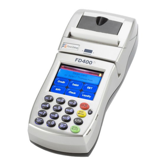
- Page 2 Thanks for choosing the First Data™ FD400 Terminal. The FD400 is an easy-to-use terminal that goes with you wherever your business takes you. Installation is quick and easy. With an integrated PIN pad and thermal printer, you will be able to process payments on the go.
- Page 3 Getting to know the FD400 Terminal There are two ports under the plastic cover on the left side of terminal. AC Input The AC input port is found on the left side of the terminal (under the plastic cover). To connect your power adapter to the FD400 lift the plastic cover and insert the connector into the AC port. Note: The mini-USB connector above the AC power input port is not for merchant use. Adapter spec: LI SHIN INT. / LSE0107A1240 Input: 100–240Vac, 50/60Hz 1A Output: 12Vdc, 3.33A Operating Temperature: 0°C to 40°C Battery pack: CHENG UEI / FD-400 7.4V, 2.3Ah Car Charger: EDAC POWER ELECTRONICS CO., LTD. / ED1025 Input: 11–16Vdc, 5A Output: 12Vdc, 2.5A RTC Battery: 3V, CR2032 Caution: Risk of explosion if the battery is replaced by an incorrect type; use only the same type of battery to protect against fire. Please dispose of used battery according to local regulations. Caution: Use only shielded signal cables to connect I/O devices to this equipment. You are cautioned that changes or modifications not expressly approved by the party responsible for compliance could void your authority to operate the equipment. Warning: This is a Class A product. In a domestic environment this product may cause radio interference in which case the user may be required to take adequate measures.
- Page 4 Let’s get started… Typical set-up time: 5–10 minutes Where to put the FD400 Terminal The FD400 terminal is designed to be used as a handheld device. When placing it on a desk or tabletop, please avoid areas with direct sunlight, objects that radiate heat, excessive dust and other electrical devices that can cause excessive voltage. Note: In order to meet the FCC RF exposure guidelines for body- worn operation, this terminal should be kept at least 8 inches (or 20 cm) from the body. Loading the paper Pop the printer cover’s latch to open the cover; then lift the cover. Load a roll of paper (Appleton POS Grade Plus 600-2.4 is recommended) into the printer. The thermal print-side of the paper will feed out facing the operator. Close the cover and tear off any excess paper.
- Page 5 Plug in the power to charge the battery Install the battery into the terminal, then connect the power cord to the power to charge the battery. It can take up to 4 hours to fully charge the battery. Once the battery is fully charged, the FD400 can run on battery power for several hours before requiring a new charge. Find the power button on the front of the terminal. Caution: The battery pack cover should be kept closed during normal operation. Caution: Risk of explosion if the battery is replaced by an incorrect type. Please dispose of used battery according to the instructions. Note: Make sure the battery is installed in the terminal before connecting to the power supply to charge. Power Button Warning: A shielded-type power cord is required in order to meet FCC emission limits and also to prevent interference with nearby radio and television reception. It is essential that only the supplied power cord be used.
- Page 6 Privacy Shield Installation The privacy shield allows customers to input their information in a safe and secure environment. Simply place the privacy shield around the perimeter of the 16-key keypad. When the privacy shield is installed, the keypad is separated into two parts; the numeric keys are protected within the shield. Warning: If the device, FD400Ti, is used without the detachable privacy shield, the following criteria needs to be met by the Installed Environment of the PED for complying with the PCI privacy screen design requirement: A. P ositioning of the PED on the check-stand in such way as to make visual observation of the PIN-entry process infeasible. • Visual shields designed into the check-stand. • Position the PED so that it is angled in such a way to make PIN spying difficult. B. P op-up (temporary) privacy shield attached to the PED mounting stand. Consumers (through education & prompting) or merchant would put the shield in place during PIN entry. C. I nstalling PED on an adjustable stand that allows consumers to swivel the terminal sideways and/or tilt it forwards/backwards to a position that makes visual observation of the PIN-entry process infeasible. • Visual shields designed into the check-stand. • Position the PED so that it is angled in such a way to make PIN spying difficult. D. P ositioning of in-store security cameras such that the PIN-entry keypad is not visible. Instructing the cardholder regarding safe PIN-entry, done with a combination of: • Signage on the PED. • Prompts on the display, possibly with a “click-through” screen. • Potentially literature at the point of sale. • A logo for safe PIN-entry process.
- Page 7 Using the card reader With the idle message displayed, select the desired transaction type. Insert the card into the card reader slot, with the magnetic stripe lying in the slot and facing the terminal. Slide the card in either direction through the slot without stopping. If the card swipe fails, check the position of the magnetic stripe and slide the card again. If failure persists, the card’s stripe may be damaged, user will have to manually enter the account number on the keypad. Follow remaining prompts on the display to complete the transaction. Refer to quick reference guide for details Using the keypad Through the keypad, the user can select transaction types and enter information. The FD400 has 16 keys that can be used to select numbers, letters, and to enter data. To enter numbers or letters, simply press the appropriate key. For example, to type the letter A, press [ALPHA]; then the number 2 key. For the second letter on the keyboard, such as B, press [ALPHA] twice then [2]. Or for C press [ALPHA] three times then [2].
- Page 8 FCC STATEMENT This Equipment has been tested and found to comply with the limits for a Class A digital device, pursuant to part 15 of the FCC Rules. These limits are designed to provide reasonable protection against harmful interference when the equipment is operated in a commercial environment. This equipment generates, uses, and can radiate radio frequency energy and, if not installed and used in accordance with the instruction manual, may cause harmful interference to radio communications. Operation of this equipment in a residential area is likely to cause harmful interference in which case the user will be required to correct the interference at his own expense. Caution: For hand held operation, keep the terminal about 8 inches (20cm) away from the body in order to comply with the FCC RF exposure guidelines. © 2010 First Data Corporation. All Rights Reserved. FD-SUG-FD400Ti-1210...