Table of Contents
Advertisement
Advertisement
Table of Contents

Related Manuals for First Data FD200Ti


Summary of Contents for First Data FD200Ti
- Page 1 FD200 Terminal quick Set-Up Guide...
- Page 2 Thanks for choosing a First Data FD200 Terminal. ™ First Data Terminals are some of the fastest, most secure point-of-sale terminals available. Installation is quick and easy. Simply follow the instructions and begin accepting card transactions today. What’s in the box? • First Data...
- Page 3 What else will you need? If connecting through Cable: • Router • Modem • Ethernet Cable • Coaxial Cable If connecting through DSL: • Router • Modem • Ethernet Cable (2) If connecting through Dial-up: • Splitter (optional) Note: To prevent damage to the FD Terminals and connected devices, we strongly recommend using a surge protector or UPS (Uninterruptible Power Supply) with a battery backup and phone/fax protection.
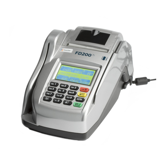
- Page 4 Getting to know the FD200 ETHERNET PHONE Port connections The pictures show an FD200 terminal. The ports on the back of the FD200 terminal enable you to add peripherals such as PIN pads and contactless readers. Phone (blue) ➔ For dial-up transactions using a phone line. USB (gray) and Serial (green) ➔ You may connect additional peripherals to the USB or COM ports, such as the FD-10 or FD-10C PIN Pads, and/or the FD-30 PIN Pad or Vivopay 4500 Contactless Readers, and/or ® MagTek MiniMICR Check Reader. ® Ethernet (yellow) ➔ For Internet transactions using Cable or DSL. Note: This is a Class I LED product. Some peripherals require a separate power source. Before connecting a USB device or similar device, remove the power cable connector from the terminal’s power port.
- Page 5 AC INPUT AC Input To connect your power supply to a wall outlet.
- Page 6 Let’s get started… Typical set-up time: 5–10 minutes Where to put the FD Terminal Place the terminal on a desk or tabletop. Avoid areas with direct sunlight, objects that radiate heat, excessive dust and other electrical devices that can cause excessive voltage. Loading the paper Pop the printer cover’s latch to open the cover; then lift the cover. Load a roll of paper (Appleton POS Grade Plus 600-2.4 is recommended) into the printer. The thermal print-side of the paper will feed out facing the operator. Close the cover and tear off any excess paper. Installing the ink Gently press the ink tray latch at the side of check reader of FD200 , and then the ink tray cover pops open. Push the black ink tray, and then flip the ink tray left gently. Put the new ink cartridge into the tray and lift the lever up to fasten the ink cartridge. Get connected You may choose an IP connection (DSL or cable) or dial-up. If you choose dial-up you can use a dedicated phone line, the same line as your fax machine or any other jack not plugged into a phone system or LAN (Local Area Network).
- Page 7 RoUTER MoDEM oUTLET Ethernet Cable Phone Cord...
- Page 8 Cable RoUTER MoDEM CABLE oUTLET Ethernet Cable Coaxial Cable...
- Page 9 Dial-up (dedicated line) Option 1 PhoNE JACk Phone Cord Dial-up Option 2 PhoNE JACk Phone Cord PhoNE/FAX Caution: To reduce the risk of fire, use only No. 26 AWG or larger UL Listed or CSA Certified Telecommunication Line Cord.
- Page 10 Plug in the power Before using the power supply, please connect all peripherals to the terminal. Not doing so may result in damage to the unit or connected devices. Connect the power cord to the power supply via the three-prong end and receiver. Find the power input on the right side of the terminal. Connect the single-pole AC adapter plug to the power input at the right side of the terminal. Turn the plug so that cord is directed toward the back of the terminal. The power supply should be the last item connected to the unit. Plug the adapter into a surge protector (strongly recommended) or a standard 120V electrical outlet. Adapter spec: DELTA: SADP-65KB B Input: 100–240Vac, 50–60Hz 1.5A output: 19Vdc, 3.42A operating Temperature: 0°C to 40°C Battery spec: 3V, CR2032...
- Page 11 Using the card reader With the idle message displayed, select the desired transaction type. Insert the card into the card reader slot, with the magnetic stripe lying in the slot and facing the terminal. Slide the card in either direction through the slot without stopping. If the card swipe fails, check the position of the magnetic stripe and slide the card again. If failure persists, the card’s stripe may be damaged, user will have to manually enter the account number on the keypad. Follow remaining prompts on the display to complete the transaction. Refer to quick reference guide for details Using the check reader Insert the check slightly into the check reader slot from left end of the terminal, with the front of check facing the terminal. The terminal will automatically process the check, once done remove from terminal. Using the keypad Through the keypad, the user can select transaction types and enter information. The FD200 has 16 keys that can be used to select numbers, letters, and to enter data. To enter numbers or letters, simply press the appropriate key. For example, to type the letter A, press [ALPHA]; then the number 2 key. For the second letter on the keyboard, such as B, press [ALPHA] twice then [2]. Or for C press [ALPHA] three times then [2].
- Page 12 FCC STATEMENT This Equipment has been tested and found lines is subject to state tariffs. to comply with the limits for a Class A TASq Technology digital device, pursuant to part 15 of the 1169 Canton Road, Marietta, GA 30066 FCC Rules. These limits are designed to (800) 827-8297 provide reasonable protection against A plug and jack used to connect this equip- harmful interference when the equipment ment to the premises wiring and telephone is operated in a commercial environment. network must comply with the applicable This equipment generates, uses, and can FCC Part 68 rules and requirements adopted radiate radio frequency energy and, if not by the ACTA. A compliant telephone cord installed and used in accordance with the and modular plug is provided with this instruction manual, may cause harmful product. It is designed to be connected interference to radio communications. to a compatible modular jack that is also Operation of this equipment in a residential compliant. See installation instructions for area is likely to cause harmful interference details. in which case the user will be required to NoTICE: This equipment meets the appli- correct the interference at his own expense. cable Industry Canada Terminal Equipment Technical Specifications. This is confirmed by the registration number. © 2010 First Data Corporation. All Rights Reserved. FD-SUG-FD200Ti-1210...