Table of Contents
Advertisement
Quick Links
Advertisement
Table of Contents

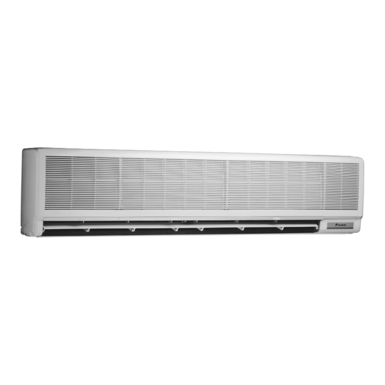
Summary of Contents for Daikin FAYP71BV1
-
Page 1: Technical Data
TECHNICAL DATA Split-Sky Air FAYP-B Wall Mounted Unit... - Page 2 Daikin Europe NV is participating Daikin Europe NV is approved by LRQA for its Quality in the EUROVENT Certification Programme. Management System in accordance with the ISO9001 Products are as listed in the EUROVENT standard.
-
Page 3: Table Of Contents
• Wall Mounted Unit • R-407C • FAYP71-100BV1 TABLE OF CONTENTS FAYP-B Features ...................... Specifications ..................Nominal capacity, capacity steps and nominal input Technical specifications Electrical specifications Dimensional drawings ..............Piping diagrams ................. Wiring diagrams ................Sound level ..................... Sound level data Sound pressure spectrum Air velocity and temperature distributions .... -
Page 4: Features
• Wall Mounted Unit • R-407C • FAYP71-100BV1 Features + Ideal for shops, restaurants or offices requiring maximum + The (wired) remote control has a programmable timer + Centralised control of several units can be achieved via 3 floor space for furniture and fittings + Fits neatly on a wall wired controls + Automatic air flow director ensures uniform airflow and... -
Page 5: Specifications
• Wall Mounted Unit • R-407C • FAYP71-100BV1 Specifications NOMINAL CAPACITY and NOMINAL INPUT For indoor units only: INDOOR UNITS FAYP71BV1 FAYP100BV1 NOMINAL INPUT Cooling 0.086 0.101 For combination indoor units + outdoor units: INDOOR UNITS FAYP71BV1 FAYP100BV1 OUTDOOR UNITS... -
Page 6: Electrical Specifications
• Wall Mounted Unit • R-407C • FAYP71-100BV1 Specifications ELECTRICAL SPECIFICATIONS For indoor units only: FAYP71BV1 FAYP100BV1 CURRENT Nominal running cooling current For combination indoor units + outdoor units: FAYP71BV1 FAYP100BV1 RP71B7V1/W1/T1 RP100B7V1/W1/T1 CURRENT Nominal running... - Page 7 • Wall Mounted Unit • R-407C • FAYP71-100BV1 Specifications NOMINAL CAPACITY and NOMINAL INPUT For indoor units only: INDOOR UNITS FAYP71BV1 FAYP100BV1 NOMINAL INPUT Cooling 0.086 0.101 Heating 0.086 0.101 For combination indoor units + outdoor units: INDOOR UNITS FAYP71BV1...
- Page 8 • Wall Mounted Unit • R-407C • FAYP71-100BV1 Specifications ELECTRICAL SPECIFICATIONS For indoor units only: FAYP71BV1 FAYP100BV1 CURRENT Nominal running cooling current heating For combination indoor units + outdoor units: FAYP71BV1 FAYP100BV1 RYP71BV1/W1 RYP100B7V1/W1 ...
-
Page 9: Dimensional Drawings
• Wall Mounted Unit • R-407C • FAYP71-100BV1 Dimensional drawings unit (mm) FAYP71B Piping direction Notes: Location of general rated name plate Right side plate outside surface In case of using infrared remote control, this position will be a signal receiver. Refer 50 or more 50 or more to the drawing of infrared remote control... -
Page 10: Piping Diagrams
• Wall Mounted Unit • R-407C • FAYP71-100BV1 Piping diagrams FAYP71-100B Refrigerant pipe connection port diameters Indoor heat exchanger Model J15.9 FAYP71 J19.1 FAYP100 Field piping J9. 5C1220T-0 To outdoor unit Field piping JA C1220T-0 Filter Indoor unit Check valve Flare connection Screw connection Flange connection... -
Page 11: Wiring Diagrams
• Wall Mounted Unit • R-407C • FAYP71-100BV1 Wiring diagrams FAYP71-100B Wired remote control To outdoor Notes unit 1. D : Terminal F, H : Connector Note) 4 b : Protective earth (screw) 2. B : Field wiring 3. In case using central remote controller, connect it to the unit in accordance with the attached instruction manual. -
Page 12: Sound Level
Cooling Heating FAYP71BV1 41/37 42/38 57/53 58/54 FAYP100BV1 45/41 45/41 61/57 61/57 Microphone Sound pressure spectrum FAYP71BV1 (Cooling) FAYP71BV1 (Heating) H (230V) H (230V) L (230V) L (230V) approximate approximate threshold hearing threshold hearing for continuous for continuous noise noise... -
Page 13: Air Velocity And Temperature Distributions
• Wall Mounted Unit • R-407C • FAYP71-100BV1 Air velocity and temperature distributions FAYP71BV1 Cooling - air velocity distribution Air flow direction: 10° (downward) FAYP71BV1 Cooling - air temperature distribution Air flow direction: 10° (downward) 4D028545 • Split - Sky Air • Indoor Units... - Page 14 • Wall Mounted Unit • R-407C • FAYP71-100BV1 Air velocity and temperature distributions FAYP71BV1 Heating - air velocity distribution Air flow direction: 65°C (downward) FAYP71BV1 Heating - air temperature distribution Air flow direction: 65°C (downward) 4D028546 • Split - Sky Air • Indoor Units...
- Page 15 • Wall Mounted Unit • R-407C • FAYP71-100BV1 Air velocity and temperature distributions FAYP100BV1 Cooling - air velocity distribution Air flow direction: 10° (downward) FAYP100BV1 Cooling - air temperature distribution Air flow direction: 10° (downward) 4D028547 • Split - Sky Air • Indoor Units...
- Page 16 • Wall Mounted Unit • R-407C • FAYP71-100BV1 Air velocity and temperature distributions FAYP100BV1 Heating - air velocity distribution Air flow direction: 65°C (downward) FAYP100BV1 Heating - air temperature distribution Air flow direction: 65°C (downward) 4D028548 • Split - Sky Air • Indoor Units...
-
Page 17: Accessories
3. For gas pipe Indoor unit and installation panel Accessories (Attached to the rear side of indoor unit.) Where to locate accessories Optional accessories Name of option Remark Kit name FAYP71BV1 FAYP100BV1 Remote controller Wired type BRC1C517 Infrared type Heat pump BRC7C510W... -
Page 18: Control Systems
• Wall Mounted Unit • R-407C • FAYP71-100BV1 Control systems Figure 1 BRC1C517 Remote control BRC1C517 • Split - Sky Air • Indoor Units... - Page 19 • Wall Mounted Unit • R-407C • FAYP71-100BV1 Control systems Name and function of each switch and display on the remote control Refer to figure 1 on the previous page. This illustration corresponds to the remote control format BRC1C type. Although the display and shape of the buttons on the BRC1B type are slightly different, they may be operated in the same manner.
-
Page 20: Safety Device Settings
• Wall Mounted Unit • R-407C • FAYP71-100BV1 Safety device settings Model Safety devices r;1 FAYP71BV1 FAYP100BV1 − − Fuse − − Fan motor thermal fuse (°C) FAYP∼BV1 OFF: 130±5 OFF: 130±5 Fan motor thermal protector (°C) ON: 83±20 ON: 83±20...


