Table of Contents
Advertisement
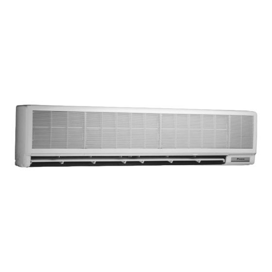
SPLIT SYSTEM
MODELS
(Wall mounted type)
FAY71FJV1
FAYP71BV1
FAY100FJV1
FAYP100BV1 FAQ100BVV1B
READ THESE INSTRUCTIONS CAREFULLY BEFORE INSTALLATION.
KEEP THIS MANUAL IN A HANDY PLACE FOR FUTURE REFERENCE.
LESEN SIE DIESE ANWEISUNGEN VOR DER INSTALLATION SORGFÄLTIG DURCH.
BEWAHREN SIE DIESE ANLEITUNG FÜR SPÄTERE BEZUGNAHME GRIFFBEREIT
AUF.
LIRE SOIGNEUSEMENT CES INSTRUCTIONS AVANT L'INSTALLATION.
CONSERVER CE MANUEL A PORTEE DE MAIN POUR REFERENCE ULTERIEURE.
LEA CUIDADOSAMENTE ESTAS INSTRUCCIONES ANTES DE INSTALAR.
GUARDE ESTE MANUAL EN UN LUGAR A MANO PARA LEER EN CASO DE TENER
ALGUNA DUDA.
PRIMA DELL'INSTALLAZIONE LEGGERE ATTENTAMENTE QUESTE ISTRUZIONI.
TENERE QUESTO MANUALE A PORTATA DI MANO PER RIFERIMENTI FUTURI.
ÄΙΑΒΑΣΤΕ ΠΡΟΣΕΚΤΙΚΑ ΑΥΤΕΣ ΤΙΣ ΟÄΗΓΙΕΣ ΠΡΙΝ ΑΠΟ ΤΗΝ ΕΓΚΑΤΑΣΤΑΣΗ ΕΧΕΤΕ
ΑΥΤΟ ΤΟ ΕΓΧΕΙΡΙÄΙΟ ΕΥΚΑΙΡΟ ΓΙΑ ΝΑ ΤΟ ΣΥΜΒΟΥΛΕΥΕΣΤΕ ΣΤΟ ΜΕΛΛΟΝ.
LEES DEZE INSTRUCTIES ZORGVULDIG DOOR VOOR INSTALLATIE. BEWAAR DEZE
HANDLEINDING WAAR U HEM KUNT TERUGVINDEN VOOR LATERE NASLAG.
LEIA COM ATENÇÃO ESTAS INSTRUÇÕES ANTES DE REALIZAR A INSTALAÇÃO.
MANTENHA ESTE MANUAL AO SEU ALCANCE PARA FUTURAS CONSULTAS.
ПЕРЕД НАЧАЛОМ МОНТАЖА ВНИМАТЕЛЬНО ОЗНАКОМЬТЕСЬ С ДАННЫМИ
ИНСТРУКЦИЯМИ. СОХРАНИТЕ ДАННОЕ РУКОВОДСТВО В МЕСТЕ, УДОБНОМ ДЛЯ
ОБРАЩЕНИЯ В БУДУЩЕМ.
INSTALLATION MANUAL
FAQ100BUV1B
Air Conditioners
English
Deutsch
Français
Español
Italiano
ëëçíéêÜ
Nederlands
Portugues
óññêèé
Advertisement
Table of Contents

Related Manuals for Daikin FAY71FJV1


Summary of Contents for Daikin FAY71FJV1
-
Page 1: Installation Manual
INSTALLATION MANUAL English SPLIT SYSTEM Air Conditioners Deutsch MODELS Français (Wall mounted type) FAY71FJV1 FAYP71BV1 FAQ100BUV1B Español FAY100FJV1 FAYP100BV1 FAQ100BVV1B Italiano READ THESE INSTRUCTIONS CAREFULLY BEFORE INSTALLATION. KEEP THIS MANUAL IN A HANDY PLACE FOR FUTURE REFERENCE. ëëçíéêÜ LESEN SIE DIESE ANWEISUNGEN VOR DER INSTALLATION SORGFÄLTIG DURCH. - Page 2 *Óçìåßùóç *Nota tal como estabelecido no Ficheiro Técnico de Construção DAIKIN.TCF.004 e com o parecer positivo de KEMA de acordo com o Certificado 59277-KRQ/ECM95-4233. *Bemærk som anført i den Tekniske Konstruktionsfil DAIKIN.TCF.004 og positivt vurderet af KEMA i henhold til Certifikat 59277-KRQ/ECM95-4233.
- Page 3 CE - OPFYLDELSESERKLÆRING CE - ILMOITUS YHDENMUKAISUUDESTA DAIKIN INDUSTRIES, LTD. declares under its sole responsibility that the air conditioning models to which this declaration relates: erklärt auf seine alleinige Verantwortung daß die Modelle der Klimageräte für die diese Erklärung bestimmt ist: ’...
-
Page 4: Table Of Contents
FAY71FJV1 FAYP71BV1 FAQ100BUV1B SPLIT SYSTEM Air Installation manual Conditioner FAY100FJV1 FAYP100BV1 FAQ100BVV1B CONTENTS 1. SAFETY CONSIDERATIONS ................1 2. BEFORE INSTALLATION ..................2 3. SELECTING INSTALLATION SITE ..............4 4. INDOOR UNIT INSTALLATION ................5 5. REFRIGERANT PIPING WORK ................7 6. -
Page 5: Before Installation
• When wiring the power supply and connecting the wiring between the indoor and outdoor units, position the wires so that the control box lid can be securely fastened. Improper positioning of the control box lid may result in electric shocks, fire or the terminals overheating. •... - Page 6 • Do not install or operate the unit in rooms mentioned below. • Laden with mineral oil, or filled with oil vapor or spray like in kitchens. (Plastic parts may deterio- rate.) • Where corrosive gas like sulfurous gas exists. (Copper tubing and brazed spots may corrode.) •...
-
Page 7: Selecting Installation Site
FOR THE FOLLOWING ITEMS, TAKE SPECIAL CARE DURING CONSTRUCTION AND CHECK AFTER INSTALLATION IS FINISHED. 1. Items to be checked after completion of work Items to be checked If not properly done, what is likely to occur Check Is the indoor unit fixed firmly? The unit may drop, vibrate or make noise. -
Page 8: Indoor Unit Installation
[ CAUTION ] Only use the included parts or parts which match the specifications when installing the unit. • Install the indoor unit no less than 2.5 m above the floor. Where unavoidably lower, take what measures are necessary to keep hands out of the air outlet. ≥... - Page 9 3. Make a through hole in the wall. • Piping can be led out from the left, right or rear sides. ( Refer to Fig. 2 ) • The drain hole is on the right side. • Select the piping route and open a through hole in the wall (φ80). Ensure the hole slopes gradually downward to the outside.
-
Page 10: Refrigerant Piping Work
[ How to detach side and bottom panels ] • Remove the screws in the side panel and pull the side panel outward (A). Then, while pushing upwards (B), slide the panel towards the front of the unit (C). (Same for both left and right sides) ( Refer to Fig. - Page 11 • When connecting the flare nut, apply ester oil Coat here with ester or ether oil. or ether oil to the flare section (both inside and out- side), and spin 3-4 times before screwing in. (Refer to Fig. 10 ) Fig.
-
Page 12: Drain Piping Work
[ PRECAUTIONS ] 1. Do not overlap insulation for fitting. (Refer to Fig. 11) 2. Tape the liquid and gas pipe together from the bend up to where they enter the unit. (Refer to Fig. 12) 3. Wrap the drain hose inside the unit with insulation tape, but sepa- Liquid pipe rate it from the refrigerant pipe. -
Page 13: Electric Wiring Work
• Use particular caution when carrying out the steps in the Fig. 15. The drain hose must lead down. WRONG GOOD WRONG Drain pipe Drain pipe Leading down WRONG The original edge must not be placed beneath the water. Fig. 15 •... - Page 14 • Be sure to ground the air conditioner. • Do not connect the ground wire to gas pipes, plumbing pipes, lightning rods, or telephone ground wires. • Gas pipes: could explode and cause fires if there was a gas leak. •...
- Page 15 CAUTION When clamping wiring, use the included clamping material and clamp firmly to prevent outside pressure being exerted on the wiring connections. When doing the wiring, make sure the wiring is neat and does not cause the control box lid to stick up, then close the cover firmly.
-
Page 16: Wiring Example
8. WIRING EXAMPLE For the wiring of outdoor units, refer to the installation manual attached to the outdoor units. Confirm the system type. • Pair type: 1 remote controller controls 1 indoor unit (standard system). • Simultaneous operation system: 1 remote controller controls 2 indoor units (2 indoor units operates equally.) •... -
Page 17: Field Setting
9. FIELD SETTING Field setting must be made from the remote controller in accordance with the installation condition. • Setting can be made by changing the “Mode No.”, “FIRST CODE NO.”, and “SECOND CODE NO.”. • For setting and operation, refer to the “FIELD SETTING” in the installation manual of the remote controller. 1. - Page 18 4. Simultaneous operation system individual setting It is easier if the optional remote controller is used when setting the slave unit. • Perform the following procedures when setting the master and slave unit separately. Procedure (1)Change the SECOND CODE NO. to “02”, individual setting, so that the slave unit can be individually set.
-
Page 19: Test Operation
Upper part of Factory setting remote controller Remote controller PC board Lower part of remote controller Only one remote controller Insert the screwdriver here and gently needs to be changed work off the upper part of remote controller. if factory settings have remained untouched. - Page 20 (2) Press the PROGRAMMING TIME button and find the unit No. which stopped due to trouble. Number of beeps 3 short beeps..Perform all the following operations 1 short beep....Perform (3) and (6) 1 long beep .....No trouble (3) Press the OPERATION MODE SELECTOR button and upper figure of the error code flashes. (4) Continue pressing the PROGRAMMING TIME button unit it makes 2 short beeps and find the upper code.
- Page 21 3. Malfunction code • For places where the error code is left blank, the “ ” indication is not displayed. Though the system continues operating, be sure to inspect the system and make repairs as necessary. • Depending on the type of indoor or outdoor unit, the malfunction code may or may not be displayed. Code Malfunction/Remarks Indoor unit’s PC board faulty...
-
Page 22: Wiring Diagram
Transmission malfunction between the outdoor control units’ inverters (outdoor unit) Open-phase (outdoor unit) PC board temperature sensor malfunction (outdoor unit) Heat-radiating fin temperature sensor malfunction (outdoor unit) Type set improper (outdoor unit) Capacity data is wrongly proset. Or there is nothing programmed in the data hold IC. Suction pipe temperature abnormal Reverse phase Reverse two of the L1,L2 and L3 leads. - Page 23 Fig. 22 English...
- Page 24 Fig. 23 English...
- Page 25 3P184443-2 EM00A030E (0608) HT...