
Related Manuals for QSC RMX Series


Summary of Contents for QSC RMX Series
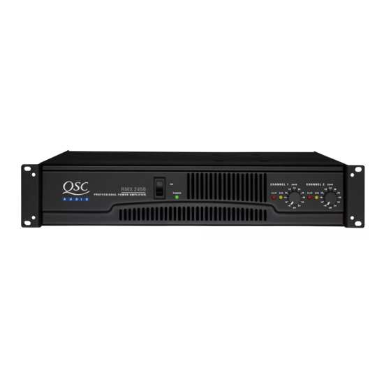
- Page 1 ▲ ▲ ▲ ▲ ▲ RMX 850 ▲ ▲ ▲ ▲ ▲ RMX 1450 ▲ ▲ ▲ ▲ ▲ RMX 1850HD ▲ ▲ ▲ ▲ ▲ RMX 2450 *TD-000098-00* TD-000098-00 QSC Audio Products, LLC Rev. C Costa Mesa, CA 92626 USA www.qscaudio.com...
-
Page 3: Technical Service Manual
Web: http://www.qscaudio.com (product information and support) http://www.qscstore.com (parts and accessory sales) Copyright 2001, 2002, 2005, 2008 QSC Audio Products, LLC All rights reserved. Document # TD-000098-00, Rev. C. Released June 2008. RMX Series Technical Service Manual (2RU models) TD-000098-00 rev. C... -
Page 4: Rmx Series Performance Specifications
RMX Series Performance Specifications RMX 850 RMX 1450 RMX 1850HD RMX 2450 OUTPUT POWER in watts FTC: 20 Hz–20 kHz @ 0.1% THD, both channels driven 8Ω per channel 4Ω per channel EIA: 1 kHz @ 0.1% THD, both channels driven 8Ω... -
Page 5: Table Of Contents
7.10 RMX 1850HD Schematic Diagram 2 of 3 Channel 2 ........................................42 7.11 RMX 1850HD Schematic Diagram 3 of 3 Power Supply ......................................43 7.12 RMX 2450 Schematic Diagram 1 of 4 Channel 1 ........................................44 RMX Series Technical Service Manual (2RU models) TD-000098-00 rev. C... - Page 6 7.16 RMX Power Transformer Configurations March 2007 and later ....................................48 7.17 RMX 850 Chassis Wiring Diagram ................................49 7.18 RMX 1450 Chassis Wiring Diagram ................................50 7.19 RMX 1850HD and RMX 2450 Chassis Wiring Diagram ........................... 51 QSC Audio Products, LLC...
-
Page 7: Introduction
1.1 Restriction of Hazardous Substances Directive (RoHS) Since April 2006, all RMX Series amplifiers are manufactured to conform to the European Union’s RoHS Directive, which reduces the amount of hazardous substances allowed in products for sale within its member nations. In electronic equipment such as audio power amplifiers, this applies primarily to certain toxic heavy metals, such as lead, which may be present in electronic components, solder, and other parts. -
Page 8: The Well-Equipped Service Bench
• • Diagonal cutters • Wire strippers Automated test equipment, such as an Audio Precision workstation, is very useful for servicing RMX amplifiers. Contact QSC Technical Services to obtain applicable AP test files. 1.5 Working with surface-mount components RMX amplifiers, like many modern electronic products, use surface-mount technology (SMT) components where appropriate in order to make high-density circuitry that is reliable and economical to manufacture. - Page 9 3 Hold the component in place and take the soldering iron away. Let the solder harden to tack the component in place. 4 Fully solder the other terminals of the component to their pads. Let the solder harden. 5 Fully solder the tacked terminal of the component to its pad. RMX Series Technical Service Manual (2RU models) TD-000098-00 rev. C...
-
Page 10: Series Description
Power supplies sensors. Unlike other recent QSC amplifiers, the RMX line uses strictly Audio circuitry conventional power supplies, with large transformers that operate at the 50 or 60 Hz frequency of the AC line. The electrical current... -
Page 11: Clip Detection
^R_0805 When the clipping stops, Q100 is no longer forward-biased, and Q100 CLIP LIMIT the gain returns to normal. 3906 SWITCH (Open to defeat clip limiter) -14V Figure 1.12 RMX Series Technical Service Manual (2RU models) TD-000098-00 rev. C... - Page 12 A protection circuit monitors the balance between Channel 1’s and Channel 2’s signals. Resistors R22 and R23 (R22A, R22B, R23A, and R23B on the RMX2450) are equal in value and QSC Audio Products, LLC...
-
Page 13: Component Identification And Pinout
(part number IC-000213-GP; was 3130-9270-0) K A G IRFZ44 TMOS power field effect transistor (part number QD-000347-GP; was 490F-Z440-5) 2N3904 (NPN) Small-signal transistor (part number QD-000204-GP; was 4860-0640-3) 2N3906 (PNP) Small-signal transistor (part number QD-000205-GP; was 4853-9060-3) RMX Series Technical Service Manual... - Page 14 Note: To install the BTA41 Triac on a channel module circuit board that originally held a MAC224 Triac, first mount it to an adapter (QSC part number SR-000117-00) and then solder the adapter to the circuit board. See Service Bulletin RMX0008 for more information.
-
Page 15: Troubleshooting: Symptoms, Causes, & Remedies
D8 and R10; also, C7 and C8 is leaky. • Bias diodes D108, D109, D208, or D209 or bias trimpots R131 or • D9, R4, and/or R7 is open. R231 is open. RMX Series Technical Service Manual... -
Page 16: Faults With Signal Present
• Check C114, C124, C214 and C224. • Severe distortion, at any load, often with abnormally high • Check or replace dual op amp U101 or U201. current draw: check the slew rate capacitors C114, C115, and QSC Audio Products, LLC... -
Page 17: Power Supply And Rail Balancing Problems
R240 permit adjustment of the current limit thresholds. See voltage divider is the likely culprit. the RMX calibration section of this manual for adjustment procedures. RMX Series Technical Service Manual... -
Page 18: Rmx Calibration Procedures
AC wires and check the amp’s idle current. If the amplifier is still at about room temperature, the idle current should match the value shown in Table 1. QSC Audio Products, LLC... - Page 19 Idle AC demand* (at ambient temperature; 0.4 A, 0.4 A, 0.6 A, 0.6 A, ±10% ±10% ±10% ±10% higher when hot) *Figures shown are for 120V amplifiers; multiply current by 0.5 for 230V or 1.2 for 100V. RMX Series Technical Service Manual...
-
Page 20: Servicing Rmx Amplifiers
QSC’s factory service. Any other operating voltage module is Channel 1 and the right is Channel 2 except in the conversions may be done only by a QSC-authorized service center RMX2450; its right module is Channel 1, and its left is Channel 2. -
Page 21: Replacement Parts
R142, R148, R149, R152, R153, R159 RE-.56006-GP 4719-5R6J-1-X RMF 2W 5.6 OHM 5% R160 RE-.68001-GP 4718-6R8J-1-X RMF 1W 6.8 OHM 5% R146, R147 RE-000250-GP 8910-0488-0 NTC RES 50 OHM R134 RMX Series Technical Service Manual (2RU models) TD-000098-00 rev. C... - Page 22 RMX850 Channel 1 Module Assembly (continued) QSC part # Old QSC part # Description Qty. Notes or Component Reference RE-000260-GP 8910-0274-0 THERMAL PTC 60C 100 OHM RE-001201-GP 471B-120J-1-X 12 5% 5W METAL OXIDE FILM R161, R162 RE-002202-GP 4718-220J-2-P RMF 1W 22R 5% AT FP...
- Page 23 J100, J200 PA-000043-00 2113-1338-0 PLATE ASSY,PLX/RMX,OUTPUT,, J103 PL-000055-00 4154-2111-0 OUTPUT POST PLUG FOR CE (RED) For European models only PL-000056-00 4154-2121-0 OUTPUT POST PLUG FOR CE (BLACK) For European models only RMX Series Technical Service Manual (2RU models) TD-000098-00 rev. C...
-
Page 24: Rmx1450 Replacement Parts
6.2 RMX1450 Replacement Parts QSC part # Old QSC part # Description Qty. Notes or Component Reference Misc. CH-000194-GP 4134-9101-0 FAN SHROUD RMX CO-000211-GP 2113-1144-0 AC INLET 250V 15A MS-000137-GP 4154-0361-0 FAN GUARD WIRE 76MM RMX MS-000138-GP 8900-9050-1 DC FAN 24V 80X80 (+5V) - Page 25 RMF 5W 1K 5% R257, R258 RE-122006-GP 4756-2226-3-06 SVR 2.2K H3 7X7 R239, R240 RE-130003-GP 471B-302J-1-X RMF 5W 3K 5% METAL R233, R235 RE-211304-GP 4717-1132-2 RMF 1/2W 11.3K 1% AT R123 RMX Series Technical Service Manual (2RU models) TD-000098-00 rev. C...
- Page 26 RMX1450 Channel 2 module (continued) QSC part # Old QSC part # Description Qty. Notes or Component Reference RE-213304-GP 4717-1332-2 RMF 1/2W 13.3K 1% AT R122, R222 XF-000190-GP 1804-1040-0 SPRING COIL 2UH (14GA WIRE) L200 Channel 2 SMT Parts CA-056001-GP...
-
Page 27: Rmx1850Hd Replacement Parts
TRIM POT,100,20 PCNT,0.15W,, R131 PT-225000-GP 4751-0110-0 RES VAR 2.5K RT ANGLE PCB R112, R212 QD-000197-GP 3700-4529-R LED 4.7MM RED W/STAND LD100, LD200 QD-000199-GP 3700-4530-Y LED 4.7MM W/STAND YELLOW LD101, LD201 RMX Series Technical Service Manual (2RU models) TD-000098-00 rev. C... - Page 28 RMX1850HD Channel 1 module (continued) QSC part # Old QSC part # Description Qty. Notes or Component Reference QD-000202-GP 4804-0040-1 DIODE IN4004 AL D10, D12, D117, D118 QD-000203-GP 4838-15V6-2 DIOD ZNR 15V 1W SILICON EPIT D100, D101, D200, D201 QD-000206-GP...
- Page 29 4718-3R3J-1-X RMF 1W 3.3 OHM 5% R246, R247 RE-.56006-GP 4719-5R6J-1-X RMF 2W 5.6 OHM 5% R260 RE-000250-GP 8910-0488-0 NTC RES 50 OHM R234 RE-000260-GP 8910-0274-0 THERMAL PTC 60C 100 OHM RMX Series Technical Service Manual (2RU models) TD-000098-00 rev. C...
- Page 30 RMX1850HD Channel 2 module (continued) QSC part # Old QSC part # Description Qty. Notes or Component Reference RE-001201-GP 471B-120J-1-X 12 5% 5W METAL OXIDE FILM R254, R255, R261, R262 RE-002202-GP 4718-220J-2-P RMF 1W 22 5% AT FP R236, R237...
-
Page 31: Rmx2450 Replacement Parts
R112, R212 (May 2002 and later) *PT-310006-GP *4750-6200-0 VR V012CPH, D-SHAFT 10K R112, R212 (April 2002 and earlier) QD-000197-GP 3700-4529-R LED 4.7MM RED W/STAND LD100, LD200 QD-000199-GP 3700-4530-Y LED 4.7MM W/STAND YELLOW LD101, LD201 RMX Series Technical Service Manual (2RU models) TD-000098-00 rev. C... - Page 32 RE-082004-GP 4720-821J-J RMG 1/10W 820R 5% 0805 R111, R211 RE-110012-GP 4720-102J-J RMG 1/10W 1K 5% 0805 R102, R126, R202 RE-115004-GP 4720-152J-J RMG 1/10W 1.5K 5% 0805 R129 RE-120004-GP 4720-202J-J RMG 1/10W 2K 1% 0805 R190, R195 QSC Audio Products, LLC...
- Page 33 XISTOR NPN 250V 0.5A MJE15032 Q205 QD-000208-GP 4860-5060-5 TR 2SA1943 T0-3P (L) Q203, Q207, Q209, Q211 QD-000209-GP 4860-5050-5 TR 2SC5200 T0-3P (L) Q204, Q208, Q210, Q212 QD-000210-GP 4860-5030-5 XISTOR PNP 250V MJE15033 Q206 RMX Series Technical Service Manual (2RU models) TD-000098-00 rev. C...
- Page 34 2113-1336-1 SPEAKON NEUTRIK 4 WIRE J100, J200 PA-000043-00 2113-1338-0 PLATE ASSY,PLX/RMX,OUTPUT,, J103 PL-000055-00 4154-2111-0 OUTPUT POST PLUG FOR CE (RED) For European models only PL-000056-00 4154-2121-0 OUTPUT POST PLUG FOR CE (BLACK) For European models only QSC Audio Products, LLC...
-
Page 35: Schematics And Diagrams
SEE TABULATION BLOCK DWG NO. RMX 2450 FINISH ISSUED PA-002450-00 (All models) NOTES: UNLESS OTHERWISE SPECIFIED NEXT ASSY USED ON SCALE SHEET APPLICATION DO NOT SCALE DRAWING 1 OF 2 RMX Series Technical Service Manual (2RU models) TD-000098-00 rev. C... -
Page 36: Rmx Assembly/Disassembly Diagram 2 Of
THIS DOCUMENT CONTAINS PROPRIETARY INFORMATION WHICH IS THE PROPERTY OF QSC AUDIO PRODUCTS, THAT MAY NOT BE DISCLOSED, REPRODUCED OR USED CHANNEL MODULES WITHOUT EXPRESS WRITTEN CONSENT FROM QSC AUDIO PRODUCTS. RMX 850: WP-008503-00; was PCB-QZ010C-PWR1 (left or Channel 1) RMX 1450: WP-014502-00;... -
Page 37: Rmx850 Schematic Diagram 1 Of
NOTES: UNLESS OTHERWISE SPECIFIED CAD SEED FILE NO. PLOT DATE: SCALE CAD FILE NO. SHEET APPLICATION DO NOT SCALE DRAWING NONE RMX850-3.sch Thu Sep 07, 2000 P:RMXQSCRMX850 PLOT DATE: Thu Sep 07, 2000 RMX Series Technical Service Manual (2RU models) TD-000098-00 rev. C... -
Page 38: Rmx850 Schematic Diagram 2 Of
THIS DOCUMENT CONTAINS PROPRIETARY INFORMATION WHICH IS THE PROPERTY OF QSC AUDIO PRODUCTS, THAT MAY NOT BE DISCLOSED, REPRODUCED OR USED WITHOUT EXPRESS WRITTEN CONSENT FROM QSC AUDIO PRODUCTS. CHANNEL-2 C201 180p-5% ^C_0805 R205 R228 R229 Q201 +VCC_B R235 +67V 3904 10.0K... -
Page 39: Rmx850 Schematic Diagram 3 Of
7.5 RMX850 Schematic Diagram 3 of 3 Power Supply RMX Series Technical Service Manual (2RU models) TD-000098-00 rev. C... -
Page 40: Rmx1450 Schematic Diagram 1 Of
REVISION THIS DOCUMENT CONTAINS PROPRIETARY INFORMATION WHICH IS THE PROPERTY DESCRIPTION EFF. DATE APPROVED / DATE OF QSC AUDIO PRODUCTS, THAT MAY NOT BE DISCLOSED, REPRODUCED OR USED PROTOTYPE RELEASE 3-01-00 WITHOUT EXPRESS WRITTEN CONSENT FROM QSC AUDIO PRODUCTS. CLEAN UP BY PHQ... -
Page 41: Rmx1450 Schematic Diagram 2 Of
7.7 RMX1450 Schematic Diagram 2 of 3 Channel 2 SIZE FSCM NO. DWG NO. SH-001451-00 NOTES: UNLESS OTHERWISE SPECIFIED SCALE CAD FILE NO. SHEET NONE RMX1450-4.sch PLOT DATE: Thu Sep 07, 2000 RMX Series Technical Service Manual (2RU models) TD-000098-00 rev. C... -
Page 42: Rmx1450 Schematic Diagram 3 Of
7.8 RMX1450 Schematic Diagram 3 of 3 Power Supply QSC Audio Products, LLC... -
Page 43: Channel 1
Gray shading indicates signal path 7.9 RMX1850HD Schematic Diagram 1 of 3 Channel 1 RMX Series Technical Service Manual (2RU models) TD-000098-00 rev. C... -
Page 44: Channel 2
Gray shading indicates signal path 7.10 RMX1850HD Schematic Diagram 2 of 3 Channel 2 QSC Audio Products, LLC... -
Page 45: Power Supply
7.11 RMX1850HD Schematic Diagram 3 of 3 Power Supply RMX Series Technical Service Manual (2RU models) TD-000098-00 rev. C... -
Page 46: Rmx 2450 Schematic Diagram 1 Of
POS STEP DRIVER THIS DOCUMENT CONTAINS PROPRIETARY +110_A INFORMATION WHICH IS THE PROPERTY C170 OF QSC AUDIO PRODUCTS, THAT MAY NOT BE DISCLOSED, REPRODUCED OR USED 47pF-50V-5% WITHOUT EXPRESS WRITTEN CONSENT FROM Q170 ^Q_BJTN_SOT-23 R170 QSC AUDIO PRODUCTS. ^C_0805 RFZ44... -
Page 47: Channel 2
7.13 RMX2450 Schematic Diagram 2 of 4 Channel 2 SIZE FSCM NO. DWG NO. SH-002451-00 NOTES: UNLESS OTHERWISE SPECIFIED SCALE CAD FILE NO. SHEET NONE RMX2450-4.sch PLOT DATE: Thu Sep 07, 2000 RMX Series Technical Service Manual (2RU models) TD-000098-00 rev. C... -
Page 48: Power Supply
THIS DOCUMENT CONTAINS PROPRIETARY INFORMATION WHICH IS THE PROPERTY OF QSC AUDIO PRODUCTS, THAT MAY NOT BE DISCLOSED, REPRODUCED OR USED WITHOUT EXPRESS WRITTEN CONSENT FROM QSC AUDIO PRODUCTS. CT_A SEE SH 1 J104:12 J21:1 RECTIFIER BR100-201 CIRCUIT +14V IS DRAWN FOR CHASSIS MTG... -
Page 49: Rmx2450 Schematic Diagram 4 Of
7.15 RMX2450 Schematic Diagram 4 of 4 Power Supply Revision RMX Series Technical Service Manual (2RU models) TD-000098-00 rev. C... -
Page 50: Rmx Power Transformer Configurations
7.16 RMX Power Transformer Configurations March 2007 and later QSC Audio Products, LLC... -
Page 51: Rmx850 Chassis Wiring Diagram
AUDIO PRODUCTS, INC. NEUT PWR PCB JP10 COSTA MESA, CALIFORNIA 1724-340A-0102 WIRING DIAGRAM, RMX 850 7.17 RMX850 Chassis Wiring Diagram NOTES: UNLESS OTHERWISE SPECIFIED SCALE SHEET NONE 1 OF 1 RMX Series Technical Service Manual (2RU models) TD-000098-00 rev. C... -
Page 52: Rmx1450 Chassis Wiring Diagram
THIS DOCUMENT CONTAINS PROPRIETARY REVISIONS INFORMATION WHICH IS THE PROPERTY DESCRIPTION EFF. DATE APPROVED/DATE OF QSC AUDIO PRODUCTS, THAT MAY NOT BE DISCLOSED, REPRODUCED OR USED OUTPUT PCB WITHOUT EXPRESS WRITTEN CONSENT FROM QSC AUDIO PRODUCTS. 1724-340C-0102 J103 E100 JP14... -
Page 53: Rmx1850Hd And Rmx2450 Chassis Wiring Diagram
7.19 RMX1850HD and RMX2450 Chassis Wiring Diagram DWG NO. FG-002450-00 RMX 2450 ISSUED SH-002450-00 NOTES: UNLESS OTHERWISE SPECIFIED NEXT ASSY USED ON SCALE SHEET FIRST APPLICATION NONE 1 OF 1 DO NOT SCALE DRAWING RMX Series Technical Service Manual (2RU models) TD-000098-00 rev. C... - Page 54 QSC Audio Products, LLC...
- Page 56 “QSC” and the QSC logo are registered trademarks of QSC Audio Products, LLC 1665 MacArthur Blvd. Costa Mesa, CA 92626 Phone +1 (714) 957-7150 (800) 772-2834 (USA only) FAX +1 (714)754-6173 www.qscaudio.com...