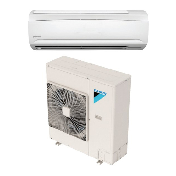
Daikin FAQ18TAVJU Installation Manual
Split system; wall-mounted type
Hide thumbs
Also See for FAQ18TAVJU:
- Service manual (298 pages) ,
- Service manual (331 pages) ,
- Operation manual (10 pages)
Table of Contents
Advertisement
SPLIT SYSTEM
MODELS
Wall-mounted type
FAQ18TAVJU
FAQ24TAVJU
Read these instructions carefully before installation.
Keep this manual in a handy place for future reference.
This manual should be left with the equipment owner.
Lire soigneusement ces instructions avant l'installation.
Conserver ce manuel à portée de main pour référence
ultérieure.
Ce manuel doit être donné au propriétaire de l'équipement.
Lea cuidadosamente estas instrucciones antes de instalar.
Guarde este manual en un lugar a mano para leer en caso
de tener alguna duda.
Este manual debe permanecer con el propietario del
equipo.
INSTALLATION MANUAL
Air Conditioners
English
Français
Español
Advertisement
Table of Contents

Summary of Contents for Daikin FAQ18TAVJU
-
Page 1: Installation Manual
INSTALLATION MANUAL SPLIT SYSTEM Air Conditioners MODELS Wall-mounted type FAQ18TAVJU FAQ24TAVJU English Français Read these instructions carefully before installation. Keep this manual in a handy place for future reference. This manual should be left with the equipment owner. Español Lire soigneusement ces instructions avant l’installation. -
Page 2: Table Of Contents
SPLIT SYSTEM Air Conditioners Installation manual CONTENTS DANGER • Refrigerant gas is heavier than air and replaces oxy- 1. SAFETY CONSIDERATIONS ........1 gen. A massive leak can lead to oxygen depletion, 2. BEFORE INSTALLATION ..........3 especially in basements, and an asphyxiation hazard 3. - Page 3 Plastic parts may deteriorate and fall off or result other than those specified by Daikin are used, fire or in water leakage. explosion may occur.
-
Page 4: Before Installation
2. BEFORE INSTALLATION 2-1 ACCESSORIES Check if the following accessories are attached to the • When unpacking the unit or moving the unit after indoor unit. unpacked, be sure to lift it by the four hanger brack- ets. Avoid putting any pressure on other parts-hori- (2) Attachment screw zontal flaps, the refrigerant piping, drain piping, and Name... -
Page 5: Selecting Installation Site
FOR THE FOLLOWING ITEMS, TAKE • Where the wall is strong enough to bear the indoor unit weight. SPECIAL CARE DURING CONSTRUCTION • Where sufficient clearance for installation and mainte- AND CHECK AFTER INSTALLATION IS nance can be ensured. FINISHED. (Refer to Fig. -
Page 6: Indoor Unit Installation
(2) Consider whether the place where the unit will be (c) Secure the installation panel (1) to the wall using installed can support the full weight of the unit, and either screws or bolts. reinforce it with boards and beams, etc. if needed •... - Page 7 (4) Remove the front panel and the control box cover. Tab position Tab position (Refer to Fig. 5) < How to remove the front panel and control box cover > (1) Open the front panel by lifting from the bottom to the point where it stops.
- Page 8 (7) Pass power supply wiring from conduit and control (9) Push on both bottom edges of the indoor unit using wiring through the wiring guide in the back of the both hands and hook the tab on the back of the unit, to the front of the unit.
-
Page 9: Refrigerant Piping Work
5. REFRIGERANT PIPING WORK Coat the flared inner surface only with ester oil or ether oil 〈For refrigerant piping of outdoor unit, see the installa- tion manual attached to the outdoor unit.〉 〈Execute thermal insulation work completely on both sides of the gas piping and the liquid piping. Otherwise, a water leak can occur.〉... -
Page 10: Drain Piping Work
• When brazing the refrigerant piping, carry out nitrogen CAUTION substitution (inserting nitrogen into the refrigerant piping to • Be sure to insulate the field piping all the way to the piping substitute air with nitrogen (refer to NOTE below)) and connection inside the unit. -
Page 11: Electric Wiring Work
Power supply Fan motor (Refer to Fig. 19) Voltage Model Volts range Plastic container for pouring FAQ18TAVJU Max. 253 60 208/230 Min. 187 FAQ24TAVJU MCA: Minimum Circuit Ampacity (A) MOP: Maximum Overcurrent Protective Device (A) W: Fan Motor Rated Output (W) -
Page 12: Wiring Example And How To Set The Remote Controller
8. WIRING EXAMPLE AND HOW TO SET Insulating tube (short) (accessory) (7) Clamp (small) THE REMOTE CONTROLLER (accessory) (5) Power supply wiring 8-1 HOW TO CONNECT WIRINGS Ground (1 in. (25 mm)) • Conduit for power supply wiring wiring Unscrew and remove the conduit mounting plate from the Insulating tube (long) control box. - Page 13 2. Tightening torque for the terminal screws. WARNING • Use the correct screwdriver for tightening the terminal • Never connect power supply wiring to the terminal block screws. If the blade of screwdriver is too small, the for remote controller wiring as this could damage the head of the screw might be damaged, and the screw entire system.
- Page 14 1. When using 1 remote controller (Normal operation) 8-3 CONTROL BY 2 REMOTE CONTROLLERS (Controlling 1 indoor unit by 2 Power Supply remote controllers) 208/230V Outdoor unit 1~ 60Hz • When using 2 remote controllers, one must be set to Control box IN/D OUT/D “MAIN”...
-
Page 15: Field Setting
9. FIELD SETTING 9-2 SETTING AIRFLOW RATE INCREASE MODE • It is possible to raise set airflow (HIGH and LOW) from the 〈Field settings may have to be performed using the field. Change the SECOND CODE NO. as shown in remote controller, depending on the type of installation.〉... -
Page 16: Test Operation
10. TEST OPERATION • The operation lamp of the remote controller will flash when a malfunction occurs. Check the malfunction code on the display to identify the point of trouble. An explanation of malfunction codes and the corresponding trouble is pro- vided in “Service precautions”... - Page 17 5151 San Felipe, Suite 500 Houston, TX 77056 3PN07521-5H EM17A032 (1809) HT...


