Table of Contents
Advertisement
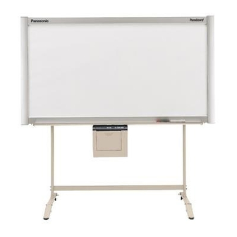
[Stand (option)]
[Wall-mounting (option)]
The unit in this picture is UB-5325.
(Stand and Wall-mounting kit are optional.)
• Please ask your dealer regarding assembly of the electronic board and instruction for wall-mounting.
Before installing this set, please read this manual completely.
Electronic Board
Installation Manual
(for qualified service personnel)
English . . . . . . . . . . . . . . . . .
Français . . . . . . . . . . . . . . . . 23- 44
Deutsch . . . . . . . . . . . . . . . . 45- 66
Español . . . . . . . . . . . . . . . . 67- 88
Italiano . . . . . . . . . . . . . . . . . 89-110
Nederlands. . . . . . . . . . . . . .111-132
Svenska . . . . . . . . . . . . . . . .133-154
中 文 . . . . . . . . . . . . . . . . . .155-176
Русский . . . . . . . . . . . . . . . .177-198
UB-5325
Model No.
UB-5825
1- 22
Advertisement
Table of Contents

Related Manuals for Panasonic UB-5325


Summary of Contents for Panasonic UB-5325
- Page 1 Electronic Board Installation Manual (for qualified service personnel) [Stand (option)] [Wall-mounting (option)] The unit in this picture is UB-5325. UB-5325 (Stand and Wall-mounting kit are optional.) Model No. UB-5825 English ....
-
Page 2: Table Of Contents
Table of Contents page Assembling the Electronic Board ......3 ●Accessories for assembling ....... . 3 ●Assembly . -
Page 3: Assembling The Electronic Board
The package includes the parts for setting up the electronic board shown below. Make sure that all of these parts are included in the package before proceeding. Illustration / Quantity Part Name Remarks UB-5325 / UB-5825 Q’ty Screen fastening bracket Upper frame cover... -
Page 4: Assembly
■ If you are using a wall-mounting kit, refer to page 19. Remove the electronic board from the shipping box. Remove the joints, then remove the electronic board from the shipping box. [UB-5325] Lower frame cover Upper frame cover Screen fastening brackets... - Page 5 Assembling the Electronic Board [UB-5825] Screen fastening brackets Wrench Eraser Wing bolts Hexagonal screws Markers Manuals, CD-ROM Upper frame cover Lower frame cover Shipping box Thermal transfer film Power cord Scanner /printer unit Screen unit Joints Joints Shipping box Caution •...
- Page 6 Assembling the Electronic Board Collapse the shipping box. Attach the scanner / printer unit to the optional stand or wall-mounting Remove the tape on the unopened side of the kit. shipping box, then collapse the box. ■ If you are using the stand (option): 1) Hang the scanner / printer unit on the stand fixtures using the wing bolts A or B.
- Page 7 Assembling the Electronic Board ■ If you are using the wall-mounting Insert the two supplied screen kit (option): fastening brackets into the screen unit frame. 1) Hang the scanner / printer unit on the wall- mounting fixtures using the wing bolts A or B (➊). 2) Screw the two wing bolts [included in the wall- mounting kit (option)] into the lower side Screen fastening...
- Page 8 Assembling the Electronic Board Fasten the brackets. Attach the screen unit to the scanner / printer unit. 1) Move the screen fastening brackets toward the center and fasten them with the four 1) Set the two provided hexagonal screws to the hexagonal screws provided.
- Page 9 Assembling the Electronic Board 3) Fasten the two screws (➊), then secure the 5) Fasten the hexagonal screw (➋) while screen unit with the two provided hexagonal pressing the gear fixing bracket in the screws (➋). direction of the arrow (➊). Hexagonal screw Gear fixing bracket Remove the tape fastening the...
- Page 10 Assembling the Electronic Board Remove the roller and paper. 2) Be sure the back of the frame cover (A) is fit to the frame of the screen unit and push down the two rivets. Bend and remove the roller (➊), then remove the paper with tape (➋).
- Page 11 Assembling the Electronic Board Attach the lower frame cover. Connect the power cord. 1) Align the lower frame cover with the metal 1) Securely fit the supplied power cord into the fittings on the left and right ends (➊), then AC inlet on the printer unit.
- Page 12 Assembling the Electronic Board Wipe the screen film surface. Soak a soft cloth with water, wring well, and wipe the screen film surface. Caution • Do not wipe the screen film surface with paint thinner, benzene, or cleaners that contain abrasives.
-
Page 13: Electronic Board Operations Check
Electronic Board Operations Check After assembling the electronic board, perform the procedures presented in the following table to make sure it functions properly. Points to Check Step Symptom Solutions Turn on the power switch. “ ” flashes after “ ” lights up. (Normal operation) (If not) Check power cord. -
Page 14: Repacking
Repacking Perform Assembly Steps 2 through 15 on pages 4 - 11 in reverse to repack the electronic board and accessories. Use the joints to fasten the shipping box. Caution • When handling the screen unit, grasp the metal frames on both sides of the screen. Do not grasp the screen film surface, as this may scratch it. -
Page 15: Assembling The Optional Stand (Kx-B061)
Assembling the Optional Stand (KX-B061) ■ Accessories The package box for the optional stand includes the parts noted below; please confirm that all parts are present before beginning installation Part name Illustration Q’ty Part name Illustration Q’ty Stand base Wing bolt M5 x 12 mm ( ”) Support... -
Page 16: Assembly
Assembling the Optional Stand (KX-B061) ■ Assembly Assembling the stand ■ Assembling the fall-prevention extension legs The fall-prevention extension legs increase the safety of the electronic board. • Caster locks are attached to Fall-prevention extension legs the back side. Caution •... - Page 17 Assembling the Optional Stand (KX-B061) ■ Assembling the stand Assemble with the holes toward the front. Pull the fall-prevention extension legs Locking down (fall-prevention extension legs casters side will be fixed by the lock pin.) (rear) Locking casters side (rear) Note Do not tighten the screw too much.
- Page 18 Assembling the Optional Stand (KX-B061) Attach the fixtures with the four wing-bolts. Assemble and install the electronic board. Refer to page 4.
-
Page 19: Optional Wall-Mounting Kit (Kx-B063)
UB-5325 is 180 kgf (397 lbs.). UB-5825 is 195 kgf (430 lbs.). 2. The position of the intended installation is of adequate size for the selected Panaboard. UB-5325 is 1,516 mm (H) × 1,550 mm (W) [5' (H) × 5' 2 " (W)]. -
Page 20: Wall-Mounting Procedure
Confirm that the wall is strong enough to support the weight of the electronic board. Caution The wall must be capable of supporting at least 1,765N [180 kgf (397 lbs.)] for UB-5325 1,912N [195 kgf (430 lbs.)] for UB-5825. Tape the Wall-mounting template on the wall. -
Page 21: Attaching The Wall-Mounting Fixtures
Optional Wall-mounting Kit (KX-B063) ■ Attaching the wall-mounting fixtures The electronic board must be mounted with the method most suited to the material of the wall. Three methods are presented here. (Other options may be available in your area.) ● Attaching to metal or concrete walls Stud plugs (sold in stores) are needed. - Page 22 Optional Wall-mounting Kit (KX-B063) ● Attaching to plasterboard walls Split-wing toggles (sold in stores) are needed. Split-wing toggle Insert each bolt through a hole Wall-mounting in the wall-mounting fixture and Plasterboard fixture into the hole in the wall beneath so that the arms of the split- Bolt wing toggle are horizontal.