Panasonic UB-5315 Operating Instructions Manual
Electronic board
Hide thumbs
Also See for UB-5315:
- Operating instructions manual (56 pages) ,
- Installation manual (20 pages) ,
- Specification sheet (4 pages)
Table of Contents
Advertisement
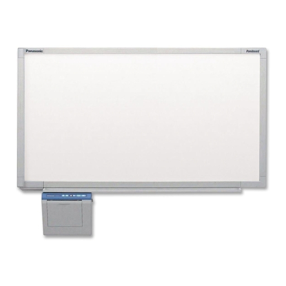
[Stand (option)]
The unit in this picture is UB-5315 series.
(Stand kit is optional.)
• Before operating this unit, please read these instructions completely.
After reading them, preserve them carefully for future reference.
• Because of the nature of the print film, all the printed text will remain on the film.
• This product is designed for installation by a qualified servicing dealer.
Installation performed by non-authorized individuals could cause safety-related problems with the operation of
this equipment.
• To locate the closest authorized dealer in your area, please call 1-800-449-8989.
(for qualified service personnel)
[Wall-mounting]
Electronic Board
Operating Instructions
With Installation Manual
Model No.
UB-5315
UB-5815
Advertisement
Chapters
Table of Contents

Related Manuals for Panasonic UB-5315


Summary of Contents for Panasonic UB-5315
- Page 1 Electronic Board Operating Instructions With Installation Manual (for qualified service personnel) [Stand (option)] [Wall-mounting] The unit in this picture is UB-5315 series. (Stand kit is optional.) UB-5315 Model No. UB-5815 • Before operating this unit, please read these instructions completely.
- Page 2 Thank you for purchasing the Panasonic Electronic Board. For optimum performance and safety, please read these instructions carefully. Accessories Q’ty Q’ty • Thermal transfer film ....1 •...
-
Page 3: Table Of Contents
• Removing Panasonic-DMS ........ -
Page 4: For Your Safety
For Your Safety CAUTION: TO PREVENT RISK OF ELECTRIC SHOCK HAZARD, DO NOT REMOVE THE COVER OF THIS PRODUCT, REFER SERVICING TO QUALIFIED SERVICE PERSONNEL. WARNING: TO PREVENT FIRE OR SHOCK HAZARD, DO NOT EXPOSE THIS PRODUCT TO RAIN OR ANY TYPE OF MOISTURE. -
Page 5: Precautions
Precautions Never remove the cover, take apart or modify the Do not position the electronic board in a location where product. This will void the warranty. it is unstable. Do not put drinks, other liquids or heavy items on the After installing or moving the electronic board, lock the tray or screen. -
Page 6: Cd-Rom
Precautions Confirm both sides of the screen are hung in the same Make sure to tighten the height adjustment handles height slots. after adjusting the screen height. Tighten Slot 3 the height adjustment Tighten Slot 3 handles Slot 2 the height adjustment handles Slot 2... - Page 7 • Use a shielded USB cable that is certified as logo by USB-IF. • If you connect the electronic board to a USB hub, it is not guaranteed to work. • Do not connect two or more Panasonic electronic boards to a computer. It may cause the computer operation to become unstable.
-
Page 8: Part Names And Functions
Part Names and Functions Scanner Screen Film Printer Tray Stand The stand is optional. Output Port Control Panel This port holds up to 10 (See page 9 for details.) sheets of output paper. Power Switch Printer Open Lever Push down this lever to AC Inlet open the printer door. -
Page 9: Control Panel
Part Names and Functions ■ Control panel Advance Key Contrast/Remaining Film Copy Key Indicator Contrast Key Multi-Copy/Stop Key 2-Screen Copy Key Multi-Copy/Error Indicator Panel Name Description This lamp indicator notifies the user when the time to replace the thermal transfer film is approaching (estimated) and of the printing contrast used during copying. -
Page 10: Installing The Thermal Transfer Film
Installing the Thermal Transfer Film Install the thermal transfer film in the printer. Set the power switch to on ( I ). • “ ” will flash on the Multi-Copy/Error Indicator when the thermal transfer film has run out. • The screen will move to home position and stop. Push down the printer open lever and open the printer door. - Page 11 Installing the Thermal Transfer Film 3) Place the blue gear on the front right groove. Blue gear 4) Place the white shaft on both sides of the back grooves. White shaft Tighten the film, then close the printer door. 1) Rotate the blue gear in the direction of the arrow to take up the slack on the film.
-
Page 12: Loading Copy Paper
Loading Copy Paper It is possible to load up to 40 sheets of Letter size copy paper (assuming a paper weight of 80 g/m Note that only Letter size paper may be used. When the unit is first used or when “ ”... - Page 13 Loading Copy Paper To prevent paper jams such as those caused by multiple sheets feeding at once, fan the paper thoroughly, square it, align it with the guide inside, and insert as far as it will go. Notes • Only use Letter size copying paper having a weight of 60 to 90 g/m as the copy paper for this unit.
-
Page 14: Making Copies
Making Copies This section describes how to copy text and illustrations drawn on the screen. Set the power switch to on ( I ). • “ ” will light on the Multi-Copy/Error Indicator to indicate that the unit is ready to copy. •... -
Page 15: Copy Types And Procedures
Making Copies ■ Copy types and procedures Copy Type Procedure Copying the front of Press the screen Copying the back of Press to move the screen to be copied to the front. the screen Press Making multiple Select the number of copies (1 to 9) by pressing copies (up to 9) necessary. -
Page 16: Replacing The Thermal Transfer Film
Thermal transfer film is replaced as follows. Notes on Replacing Thermal Transfer Film • Only use the designated product (UG-6001) from Panasonic as the replacement film. (Note that using another type of replacement film may result in degraded printing quality or damage to the unit.) •... -
Page 17: Paper Jams
Paper Jams Remove paper jams by the following procedure when copy paper does not come out of the output port or when “ ” flashes on the Multi-Copy/Error Indicator. Push down the printer open lever to open the printer door. Remove the thermal transfer film with both hands. - Page 18 Paper Jams Install the thermal transfer film. • Refer to steps 3 and 4 in the section of “Installing the Thermal Transfer Film” on pages 10, 11. • “ ” flashing on the Multi-Copy/Error Indicator will go out. Notes • If “ ”...
- Page 19 Paper Jams To prevent paper jams such as those caused by multiple sheets feeding at once, fan the paper thoroughly, square it, align it with the guide inside, and insert as far as it will go. Note • Do not stack more copy paper in the unit than the maximum paper limit indicated by the guide (see figure to the left) as this may result in paper jams.
-
Page 20: Screen Height Adjustment
Screen Height Adjustment The screen can be adjusted at 3 levels except for the lowest level. The lowest level of the board attachment frame is designed for installation of the screen, so the printer cannot be attached at this level. Adjust the level of the screen unit as follows. - Page 21 Screen Height Adjustment Tighten the height adjustment handles. Height Be sure to tighten the height adjustment handles adjustment handles firmly after adjusting the level of the screen. Height adjustment handles Store the step frame by hanging it on the board Step frame attachment (upper).
-
Page 22: Computer Interfacing
Speed USB 2.0, this electronic board functions with it is not guaranteed to work. Full Speed USB 2.0. • Do not connect two or more Panasonic electronic Microsoft® Windows® 98 operating system boards to a computer. It may cause the computer (hereafter Windows 98) operation to become unstable. -
Page 23: Installing Drivers / Board Image Capture
Computer Interfacing ■ Installing Drivers / Board Image When the following window appears, check Capture that the electronic board is not connected to your computer and click [OK]. The USB, printer, TWAIN driver and Board Image Capture are installed in your computer by following procedures. -
Page 24: Installing Quick Image Navigator / Panasonic-Dms
Windows 7: Quick Image Navigator For Windows 98 / Windows Me: Panasonic-DMS ■ Removing Drivers / Board Image If Panasonic-DMS is already installed, you do not need to uninstall it. Capture / Quick Image Navigator If you need to remove the USB driver, printer driver, Power on your computer and start Windows. -
Page 25: Removing Panasonic-Dms
(Scan) button or the ■ Removing Panasonic-DMS (2-Screen Scan) button. • When scanning is completed, the Save Scan If you need to remove Panasonic-DMS, perform the Image dialog box appears. following steps. Power on your computer and start Windows. Click [Start], move the pointer to Programs–... -
Page 26: Scanning With The Quick Image Navigator / Panasonic-Dms
Quick Image Navigator or Panasonic-DMS. (scanner) icon on the Toolbar. To start Board Image Capture, click [Close] in For Panasonic-DMS: Click the File menu, then the Panaboard Operation Panel window, then click Acquire Image..., or click the (scanner) start Board Image Capture. -
Page 27: Panaboard Operation Panel
Computer Interfacing ■ Panaboard Operation Panel It is possible to perform the same operations as with the electronic board control panel (page 9) from the following Panaboard Operation buttons. Note • While the Panaboard Operation Panel is displayed, the Copy Key and 2-Screen Copy Key on the electronic board control panel are used for scanning images into the computer. -
Page 28: Printing
Computer Interfacing Panel Name Description Advance Button Clicking this button advances the screen from right to left. 2-Screen Copy This button causes the front and back of the screen to be Button copied on a single sheet of paper. Copy Button This button causes the screen to be copied. -
Page 29: Daily Care And Maintenance
Daily Care and Maintenance Always turn off the power switch and unplug the power plug when cleaning outside and inside the unit. ■ Cleaning the screen and the unit Gently wipe the screen film and unit with a water- dampened cloth that has been thoroughly wrung. Notes •... - Page 30 Daily Care and Maintenance Clean the Printer Head Dampen the tip of a cotton swab in ethyl alcohol and gently wipe the printer head. Note • Never touch the printer head or the surrounding area with your hands as this may disable copying. Cotton swab Printer head (Gold)
-
Page 31: Help Troubleshooting
Troubleshooting Treat problems according to the information given in the table below. If problems still persist, call your dealer for service. Symptom Care and Remedy Page Power switch is on but the Check that the power plug is securely plugged in. –... - Page 32 Panasonic- 2. Install the old Panasonic-DMS. DMS. 3. Install the new Panasonic-DMS in the same folder with the old one. The old Panasonic-DMS is not uninstalled if the old version of the Panasonic Document Panasonic-DMS has been installed before installing the new one.
-
Page 33: Meanings Of Error Codes
Troubleshooting ■ Meanings of error codes The following table describes the meaning of each of the symbols which may flash in the Multi-Copy/Error Indicator. Indication Cause Remedy Page Data transfer error Connect the USB cable securely. (Error) Remove any chart paper attached to The screen will not move. -
Page 34: Specifications
Specifications Model No. UB-5315 UB-5815 Power supply AC 100 - 120 V, 50/60 Hz Power consumption 1.4 A (Operational) 1334 mm × 1372 mm 1334 mm × 1735 mm External dimensions (Height × Width × Depth, × 212 mm × 212 mm "... - Page 35 Installation Manual (for qualified service personnel) Table of Contents page Assembling the Electronic Board ..... . 36 ●Accessories for assembling ....... 36 ●Assembly .
-
Page 36: Assembling The Electronic Board
■ Accessories for assembling The package includes the parts for setting up the electronic board shown below. Make sure that all of these parts are included in the package before proceeding. Illustration/Quantity Part Name Remarks UB-5315 UB-5815 Q’ty Board attachment (upper) [*Wall-mounting... -
Page 37: Assembly
Assembling the Electronic Board ■ Assembly Assemble the optional stand or wall-mounting fixture. ■ If you are using a stand, refer to page 46. ■ If you are using a wall-mounting fixture, refer to page 50. Remove the electronic board from the shipping box. Remove the joints, then remove the electronic board from the shipping box. - Page 38 Assembling the Electronic Board Collapse the carton box. Hang the screen unit to the board attachment (upper). Remove the tape and the staples on the unopened side of the carton box, Hold the side covers of the screen unit then collapse the box. and hang two hooks of the screen unit on the left side of the board Remove the tape...
- Page 39 Assembling the Electronic Board Extend the screen unit. Extend the screen unit. Open the center and right panels of Hang the right hook of the screen unit the screen unit as shown below and on the board attachment (upper). remove the cushion. Right hook Cushion Caution...
- Page 40 Assembling the Electronic Board ■ Adjusting the level of the screen Hang the screen in the desired slots of the slide plates and tighten the unit (Step 12–15: only for use of handles. the optional stand) At the lowest level of the board attachment frame, the printer cannot be installed.
- Page 41 Assembling the Electronic Board After hanging the screen, fix the Tighten the screws for the printer stopper screw (left side only). unit. This prevents the user from adjusting Use four screws for the optional stand the screen height at the lowest level by and two screws for the wall mounting.
- Page 42 Assembling the Electronic Board Connect the cables (2) to the screen Attach the cover (upper). panel connectors. Hook the cover with the projections on both sides, then cover the top of the board attachment (upper). Board attachment (upper) Remove the folding support screw Cover (upper) on the front side of the screen unit, then store the folding support on...
- Page 43 Assembling the Electronic Board Attach the cover (lower). Attach the rear cover. (only for use of the optional stand) Push the cover in the direction of the arrow until it clicks. Fix the cover with the wing bolt. Adhesive tape (UB-5815 only) Rivets...
-
Page 44: Electronic Board Operations Check
Electronic Board Operations Check After assembling the electronic board, perform the procedures presented in the following table to make sure it functions properly. Points to Check Step Symptom Solutions Turn on the power switch. “ ” flashes after “ ” lights up. (Normal operation) (If not) Check power cord and cables. -
Page 45: Repacking
Repacking Perform Assembly Steps 2 through 24 in reverse to repack the electronic board and accessories. Use the joints to fasten the shipping box to the lower box. Board attachment (lower) Board attachment (upper) Cover (upper) Manuals, CD-ROM Thermal transfer film Power cord Screws and spacers Eraser... -
Page 46: Assembling The Optional Stand (Ue-608005)
Part name Illustration Q’ty Part name Illustration Q’ty Base pipe Screw Height Reinforce pipe adjustment handle Extension pipe (For UB-5315) Extension pipe (For UB-5815) Side pipe Step frame Fall-preven- Slide plate tion extension (Left) Slide plate Wrench (Right) (For stand) -
Page 47: Assembly
, hold the nut with pliers. ■ Assembling the stand Slide sheet Side pipe Extension pipe S is used Reinforce pipe for UB-5315. Slide sheet Extension pipe L is used for UB-5815. Base pipe Base pipe Extension pipe • Assemble the side pipes with the slide sheets facing inside. - Page 48 Assembling the Optional Stand (UE-608005) Assembling the board attachment frame Stamp “UL” Board attachment (upper) Stamp “UR” Slide plate (left) Stamp “LL” Slide plate Stamp “LR” (right) Board attachment (lower) • The board attachments (upper and lower) are supplied with the electronic board. •...
- Page 49 Assembling the Optional Stand (UE-608005) Step B Place the screws with the board attachment frame in the grooves of the side pipes. Board attachment frame Side pipe • When the side pipe leans to the inside, stand it up and attach the board attachment frame. Step C Insert the screws into the side pipes from the inside.
-
Page 50: Wall-Mounting
UB-5815 is 135 kgf (298 lbs.). 2. The position of the intended installation is of adequate size for the selected Panaboard. UB-5315 is 1,334 mm (H) × 1,372 mm (W) [4' 4 " (H) × 4' 6" (W)]. UB-5815 is 1,334 mm (H) × 1,735 mm (W) [4' 4 "... -
Page 51: Wall-Mounting Procedure
Confirm that the wall is strong enough to support the weight of the electronic board. Caution The wall must be capable of supporting at least 1226N [125 kgf (276 lbs.)] for UB-5315 1324N [135 kgf (298 lbs.)] for UB-5815. 1) Assemble the wall-mounting template by taping the Wall-mounting template 1 (TOP) to Wall-mounting template 2 (BOTTOM). -
Page 52: Attaching The Wall-Mounting Fixtures
Wall-mounting ■ Attaching the wall-mounting fixtures The electronic board must be mounted with the method most suited to the material of the wall. Three methods are presented here. (Other options may be available in your area.) ● Attaching to metal or concrete walls Stud plugs (sold in stores) are needed. - Page 53 Wall-mounting ● Attaching to wooden walls Use wood screws (sold in stores). Wall-mounting fixture Wood screw For the correct hole size, refer to the instructions for the particular wood screws used. Wooden wall...
- Page 56 Panasonic System Networks Company of America Unit of Panasonic Corporation of North America One Panasonic Way, Secaucus, New Jersey 07094 © Panasonic System Networks Co., Ltd. 2002 PJQXB0044VA-F K0303E5020...