Table of Contents

Related Manuals for Dimplex VFMi 20 C


Summary of Contents for Dimplex VFMi 20 C
-
Page 1: Table Of Contents
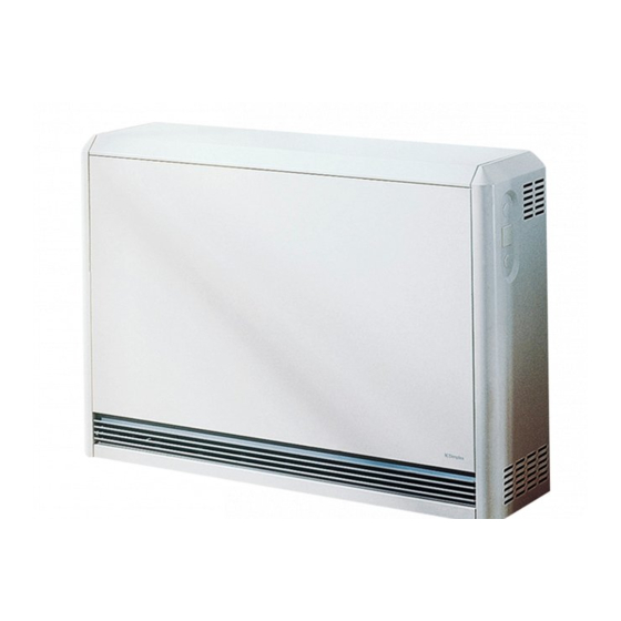
VFMi C ThermoComfort mechanic Speicherheizgerät Storage Heater Montage- und Gebrauchsanweisung Installation and Operating Instructions Inhalt Contents Gebrauchshinweise Operating Instructions Anlieferungszustand, Aufstellung Condition as Received, Installation Gerätemontage Device Installation Elektrischer Anschluss Electrical Connection Inbetriebnahme, Geräteinformation Technical Device Information Garantie, Kundendienst, Anschrift Address 459272.66.24 01/11/C... -
Page 2: Gebrauchshinweise
Gebrauchshinweise für den Benutzer Deutsch Allgemeine Hinweise • Keine Gegenstände in das Gerät einführen oder in Berührung bringen. Dies könnte zu Funktionsstörungen Bei der Installation, dem Betrieb und der Wartung ist diese oder zum Entzünden der Gegenstände führen. Anweisung zu beachten. Dieses Gerät darf nur von einem •... - Page 3 Deutsch Gebrauchshinweise für den Benutzer Aufladung-manuell (Handbetrieb) Kleine Störungen selbst beheben Raum zu kalt Wenn die Aufladung am Gerät manuell geregelt werden soll, wird der Drehknopf für Aufladung auf die Achse des Einstel- • Sicherungen für Speicherheizgeräte in der Schaltvertei- lers aufgesteckt.
-
Page 4: Anlieferungszustand, Aufstellung
- wenn zu erwarten ist, dass die Standfüße in den Boden einsinken, so dass der Luftaustausch unter dem Speicherheizgerät behindert wird. Maße Leitungseinführung Maß A VFMi 20 C 626 mm VFMi 30 C 776 mm VFMi 40 C 926 mm... -
Page 5: Gerätemontage
Deutsch Gerätemontage 1. Gerät aus der Verpackung nehmen. Verpakkungsmateri- 3. Vorderwand nach vorne aufschwenken und aus der obe- al ordnungsgemäß entsorgen. ren Umkantung herauslösen. Elektrische Anschlussleitun- gen einführen und zugentlasten. Die beiden seitlichen Wandanschlussleisten an der Geräte- rückwand anschrauben. Obere Wandanschlussleiste an den Leitungen so kürzen, dass sie im Betrieb keine heißen Gerä- beiden seitlichen Wandanschlussleisten anschrauben. - Page 6 Gerätemontage Deutsch 5. Kernraumabdeckung entfernen. Dazu die mittlere Befe- 7. Untere Steinreihe von rechts beginnend in den Kernraum stigungsschraube herausschrauben, einsetzen. Kernraumabdeckung etwas anheben, herausschwenken und nach rechts ziehen. Die Kernraumabdeckung so abstel- len, dass die Wärmedämmung nicht beschädigt werden kann.
- Page 7 Deutsch Gerätemontage 9. Zweite und dritte Steinreihe einsetzen. Zweiten Heizkör- 11. Oberste Steinreihe in gleicher Weise einsetzen. per einschieben. Gleitfähigkeit der Heizkörper prüfen. Verklemmte Heizkörper führen zur Geräuschentwicklung. Luftausblasraum und Schaltraum reinigen. 10. Nach Einlegen der vierten Steinreihe oberen Heizkörper 12.
- Page 8 Gerätemontage Deutsch 13. Die Zwischenwand und die Heizkörper-Anschlussleitungen sind mit Nummern (1 -6) versehen. Anschlussleitungen auf die Heizkörperenden aufstecken. Lose Kabel am Kabelbaum fixieren. 14. Leistungsschild des Heizkörpersatzes auf das graue Feld des Gerätetypschildes aufkleben. Aufladung Entladung Lüfter Gewicht Zusatzheizung...
-
Page 9: Elektrischer Anschluss
Deutsch Elektrischer Anschluss 15. Elektrischen Anschluss an der Klemmleiste des Gerätes vornehmen. Anschlussbeispiel: Mit Heizungsschütz und wandmontiertem Raumtemperaturregler. Schaltbildlegende - Vorwiderstand für Lüfter (nicht alle Typen) A1/Z1, A2/Z2 - Steuersignal AC-Aufladesteuerung - Steuerwiderstand (Aufladung) - Heizungsschütz - Zusatzheizung (Zubehör) L1, L2, L3 - Außenleiter - Raumtemperaturregler (Zubehör) - Ansteuerung Lüfter... -
Page 10: Inbetriebnahme, Geräteinformation
B x H x T HFi 212 1250 W HFi 216 1600 W 3/NPE 626 x 672 x 250 VFMi 20 C 4 x 25 16 kWh 98 kg 34 kg HFi 220 2000 W 400V 50Hz HFi 227*... -
Page 11: Operating Instructions
English Operating Instructions for Users General Information • Do not insert any objects into the device or bring any objects into contact with the device. This could lead to For installation, operation and maintenance, please observe malfunctions or the objects might ignite. these instructions. - Page 12 Operating Instructions for Users English Manual Charging (Manual Operation) Temperature Management If the charging of the device is to be controlled manually, the Room Too Cold charging knob must be placed on the axis of the adjuster. • Check the breaker/fuses for the storage heaters in the Remove the cap at the front panel of the storage heater.
-
Page 13: Condition As Received, Installation
Dimensions of cable entry Type Dimension A VFMi 20 C 24 5/8“ (626 mm) VFMi 30 C 30 1/2“ (776 mm) VFMi 40 C 36 1/2“ (926 mm) VFMi 50 C 42 3/8“... -
Page 14: Device Installation
Device Installation English 1. Remove the packaging. Dispose of the packaging mate- 3. Swing open the front panel to the front and remove it from rial according to local regulations. the upper edging. Insert the electrical connecting lines and provide strain relief. Screw the 2 lateral wall spacers to the device back panel. - Page 15 English Device Installation 5. Remove the core room cover. Remove the central 7. Place the lower row of bricks into the core room starting fastening screw, slightly lift the core room cover, swivel it out from the right. and pull it out to the right. Position the core room cover so that the thermal insulation is not damaged.
- Page 16 Device Installation English 9. Position the second and third rows of bricks. Insert the 11. Position the top row of bricks in the same way. second heating element. Test the mobility of the heating elements. Jammed heating elements lead to noise generation. Clean the air outlet area and the switchbox.
- Page 17 English Device Installation 13. The partition and the heating element connecting leads are marked with numbers (1-6). Plug the connecting leads onto the heating element ends. Fasten loose cables to the cable harness. 14. Attach the extra rating label supplied with the heater accessories onto the marked field of the rating plate. ChargingDischarging Weight Supplementary heating...
-
Page 18: Electrical Connection
Electrical Connection English 15. Carry out the electrical connection to the terminal strip of the device. Connection example: With heating contactor and wall-mounted thermostat. Circuit diagram legend A1/Z1, A2/Z2 - Control signal AC charge control - Control resistors (charging) - Heating contactor - Supplementary heating (accessories) L1, L2, L3 - External conductors... -
Page 19: Technical Device Information
English Start-Up, Technical Device Information Start-Up Repair Notice When all mounting and connection work has been Electric storage heaters may only be repaired by qualified completed, the functioning of the unit is to be tested. personnel. Repairs which are improperly carried out can endanger the safety of the user. -
Page 20: Garantie, Kundendienst, Anschrift
Für die Auftragsbearbeitung werden die Erzeugnisnummer E-Nr. und das Fertigungsdatum FD des Gerätes benötigt. Diese Angaben befinden sich auf dem Typschild. Bereitschaftsdienst in Notfällen auch an Wochenenden. Glen Dimplex Deutschland GmbH Telefon/Telephone +49 (0) 9221 709 564 Technische Änderungen vorbehalten...