
Related Manuals for Lennox ComfortSense 5500


Summary of Contents for Lennox ComfortSense 5500
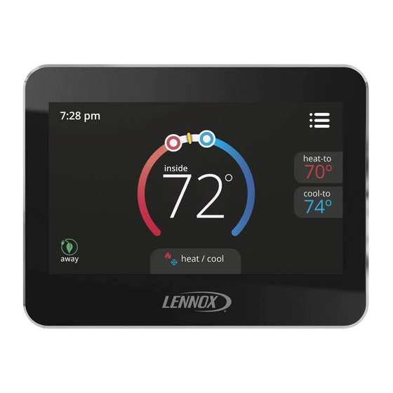
- Page 1 ® 507501-02 ComfortSense 5500 6/2018 Installation and Setup Guide Supersedes 5/2017...
-
Page 2: Table Of Contents
Table of Contents Shipping and Packing List ® ComfortSense 5500 touchscreen, 7-day pro Shipping and Packing List ..... grammable thermostat with back plate Description . -
Page 3: Dimensions (H X W X D)
menu-driven touch-screen display equipment maintenance reminders CAUTION This thermostat supports single-stage non-heat pump units. This is a 24VAC low-voltage thermostat. Do not install on voltages higher than 30VAC. Dimensions (H x W x D) Do not short (jumper) across terminals on the gas Case dimensions: 3-5/16 x 4-5/16 x 7/8 in. -
Page 4: Installation
DO NOT WARNING Install on voltages higher than 30VAC. Always turn off power at the main power source Short (jumper) across terminals on the gas by switching the circuit breaker to the OFF posi valve or at the system control to test installa tion before installing or removing this thermostat. - Page 5 Radiant heat from sun or appliances. CUT OR DRILL A SMALL HOLE Concealed pipes and chimneys. FOR THERMOSTAT WIRING Unheated (uncooled) areas such as an outside wall behind the thermostat. ¾” x ¾” PULL ABOUT 3” OF THERMOSTAT WIRE THROUGH OPENING AND RE MOVE OUTER THERMOSTAT WIRE JACKET.
- Page 6 TRIM 1/4” INSULATION FROM END OF EACH WIRE (USE A LEVEL) ALIGN WALL PLATE 1/4” DRILL 3/16” HOLES AT MARKED LOCATIONS ON WALL FOR ANCHORS USE UNIT WALL PLATE AS TEMPLATE TO MARK DESIRED MOUNTING HOLE LOCATIONS ON WALL. NOTE: INSTALLATION OF WALL PLATE IS OPTIONAL.
- Page 7 Thermostat Installation with Wall Plate F - Place wall plate H - Attach back plate J - Attach thermostat to over holes in wall. to wall plate. back plate. G - Insert wall anchors I - Insert provided screws through back and wall through wall plate into wall.
-
Page 8: Wiring Thermostat
Wiring thermostat TERMINAL DESIGNATIONS 1. Connect wiring between thermostat, indoor C - Common 24 VAC unit, and outdoor unit as shown in the appropri ate wiring diagram. G - Fan relay 2. Seal the hole in the wall with a suitable material to prevent drafts from entering the thermostat W1 - 1st stage heating (electric or gas heat) case. - Page 9 TYPICAL HEAT ONLY SYSTEM...
-
Page 10: Installer Settings
Installer Settings installer settings < installer settings must be set menu by qualified person. notifications confirm Figure 3. Installer Menu Screen Confirmation performance report 3. Available options are as follows: < installer settings edit schedules system setup > residual cool >... -
Page 11: System Setup
System Setup to select desired deadband. Touch < to return to pre vious menu. Sets the thermostat heat options. Smooth Set Recovery (SSR) Options are enable or disable. Default is Disabled. system settings < When enabled, smooth set back begins recovery up to two hours before the programmed time so that the programmed temperature is reached at the corre... -
Page 12: Custom Reminders
If the system is running in compressor protection, the home screen displays “WAIT” only if there is IMPORTANT cooling call for the compressor (Y1). RESET SETTINGS erases all programming and If compressor protection is running and there is a returns the thermostat to the factory conditions, demand for electric heating, the system waits for the including the installer settings. -
Page 13: Unit Part (Catalog) & Serial Numbers
This Touching the OFF button next to the desired option identifies the Lennox Catalog Number, Part Number will change the status to ON and will enable the relay and Serial Number. Separate the base plate from for that terminal. -
Page 14: Diagnostic Information
Diagnostic Information Priority 0:high Error Screen Message Action to Clear / Recovery Condition System Action Code Text 1:middle Type Condition 2:low High temperature protec All stages of heat are turned off high Once temperature drops tion when outdoor ambient by safety relay. This error is temperature critical below 96°F (35.6°C), the... -
Page 15: Reminder Information
Reminder Information Error Message Screen Text Action to Clear / Recovery Condition Code Type replace media filter replace UV lamp replace humidity pad routine system check-up reminder Touch either done to clear the reminder or remind later button. replace metal insert for pure air user editable user editable Supported Configurations... -
Page 16: Installation Checklist
Installation Checklist Item Item Number Is the thermostat level where mounted on the wall? Is the thermostat installed away from direct sunlight or discharge air vents? Has the thermostat been wired correctly based on the type of equipment in stalled (air handler, outdoor unit and accessories? Is the thermostat wiring secured tightly to the terminals? Is the common wire (terminal C) connected? Has the System Test Mode located under the installer settings been used to...