Table of Contents
Advertisement
User's Manual
Οδηγίες Χρήσης
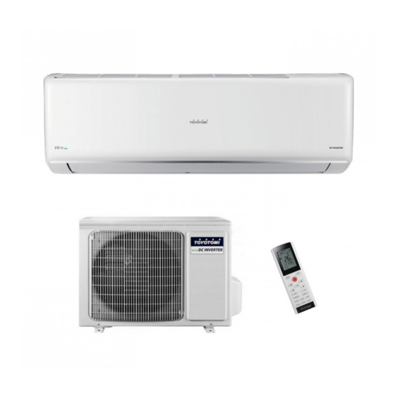
ΚΛΙΜΑΤΙΣΤΙΚΟ ΤΟΙΧΟΥ ΤΥΠΟΥ INVERTER
WALL MOUNTED AIR CONDITIONER INVERTER TYPE
MODELS/ΜΟΝΤΕΛΑ
HTN/HTG-09IV
HTN/HTG-12IV
Thank you for purchasing our product.
Before using this product, be sure to read this Instruction Manual to ensure proper usage. Please
keep this manual for later reference.
Improper use of this product may result in a malfunction, failure, unexpected accident, or create
a potential hazard.
Ευχαριστούμε για την επιλογής σας στο κλιματιστικό TOYOTOMI.
Για τη σωστή του χρήση παρακαλούμε διαβάστε το εγχειρίδιο χρήσης προσεκτικά, πριν θέσετε
τη μονάδα σε λειτουργία και κρατήστε το σε καλή κατάσταση για μελλοντική αναφορά.
Advertisement
Table of Contents

Related Manuals for Toyotomi HTN/HTG-09IV


Summary of Contents for Toyotomi HTN/HTG-09IV
- Page 1 Improper use of this product may result in a malfunction, failure, unexpected accident, or create a potential hazard. Ευχαριστούμε για την επιλογής σας στο κλιματιστικό TOYOTOMI. Για τη σωστή του χρήση παρακαλούμε διαβάστε το εγχειρίδιο χρήσης προσεκτικά, πριν θέσετε τη μονάδα σε λειτουργία και κρατήστε το σε καλή κατάσταση για μελλοντική αναφορά.
- Page 2 2087.5...
-
Page 3: Operation And Maintenance
Precautions WARNING Operation and Maintenance This appliance can be used by children aged from 8 years and above and persons with reduced physical, sensory ormental capabilities or lack of experience and knowledge if they have been given supervision or instruction concerning use of the appliance in a safe way and understand the hazards involved. - Page 4 Precautions WARNING Maintenance must be performed by qualified professionals. Otherwise, it may cause personal injury or damage. Do not repair air conditioner by yourself. It may cause electric shock or damage. Please contact dealer when you need to repair air conditioner. Do not extend fingers or objects into air inlet or air outlet.
- Page 5 Precautions WARNING Attachment Installation must be performed by qualified professionals. Otherwise, it may cause personal injury or damage. Must follow the electric safety regulations when installing the unit. According to the local safety regulations, use qualified power supply circuit and circuit break. Do install the circuit break.
- Page 6 Precautions WARNING Do not put through the power before finishing installation. If the supply cord is damaged, it must be replaced by the manufacturer, its service agent or similarly qualified persons in order to avoid a hazard. The temperature of refrigerant circuit will be high, please keep the interconnection cable away from the copper tube.
- Page 7 Precautions WARNING For the air conditioner with plug ,the plug should be reachable after finishing installation For the air conditioner without plug, an circuit break must be installed in the line. If you need to relocate the air conditioner to another place, only the qualified person can perform the work.
- Page 8 BLOW BLOW...
-
Page 9: Buttons On Remote Controller
Buttons on remote controller ON/OFF Press it to start or stop operation. MODE Press it to select operation mode (AUTO/COOL/DRY/FAN/HEAT). BLOW Press it to decrease temperature setting. Press it to increase temperature setting. Press it to set fan speed. Press it to set up & down swing angle. HEALTH SAVE (page 9) health function. -
Page 10: Introduction For Buttons On Remote Controller
Introduction for buttons on remote controller BLOW MODE icon Up & down swing icon If MODE button is pressed, is displayed when pressing current operation mode icon the up & down swing down button. AUTO, COOL, Press this button again to clear the DRY, FAN or HEAT... -
Page 11: Remote Controller Description
Introduction for buttons on remote controller Remote Controller Description ON/OFF: the unit. MODE Each time you press this button, a mode is selected in a sequence that goes from AUTO, COOL, DRY, FAN, and HEAT *, as the following: *Note: Only for models with heating function. After energization, AUTO mode is defaulted. - Page 12 Introduction for buttons on remote controller HEALTH SAVE: HEALTH function. Pressing SAVE part of this button, is displayed and the unit goes into SAVE operation mode. Press SAVE part of the button again to cancel SAVE function. During SAVE operation, the temperature and fan speed is not adjustable. Press button to start or stop left &...
-
Page 13: Replacement Of Batteries
Introduction for buttons on remote controller SLEEP : Press this button to go into the SLEEP operation mode. Press it again to cancel this function. This function is available in COOL, HEAT (Only for models with heating function) mode to maintain the most comfortable temperature for you. LIGHT: the display’s light. -
Page 14: Emergency Operation
Emergency operation If remote controller is lost or damaged, please use auxiliary button to turn on or turn off the air conditioner. The operation in details are as below: air conditioner. When the air conditioner is turned on, it will operate under auto mode. - Page 15 Clean and Maintenance Open panel Pull out the panel to a certain Use dust catcher or water to angle as shown in the fig. clean the filter. When the filter is very dirty, use the water (below 45 ) to clean it, and then put it in a shady and cool place to dry.
- Page 16 Clean and Maintenance 1. Check whether air inlets and air outlets are blocked. 2. Check whether air switch, plug and socket are in good condition. 3. Check whether filter is clean. 4. Check whether mounting bracket for outdoor unit is damaged or corroded. If yes, please contact dealer.
-
Page 17: Malfunction Analysis
Malfunction analysis General phenomenon analysis Please check below items before asking for maintenance. If the malfunction still can’t be eliminated, please contact local dealer or qualified professionals. Whether it's interfered severely Pull out the plug. Reinsert (such as static electricity,stable the plug after about 3min, and voltage)? then turn on the unit again. - Page 18 Malfunction analysis Power failure? Wait until power recovery. Is plug loose? Reinsert the plug. Air switch trips off or fuse is Ask professional to replace burnt out? air switch or fuse. Air condit- Wiring has malfunction? Ask professional to replace it. ioner can’t Unit has restarted immediately operate...
- Page 19 Malfunction analysis Whether there’s odour source, Eliminate the odour source. Odours are such as furniture and cigarette, emitted Clean the filter. etc. Air conditioner Whether there’s interference, Disconnect power, put back operates nor- such as thunder, wireless power, and then turn on the mally suddenly devices, etc.
-
Page 20: Error Code
Malfunction analysis Error Code When air conditioner status is abnormal, temperature indicator on indoor unit will blink to display corresponding error code. Please refer to below list for identification of error code. Error code Troubleshooting It can be eliminated after restarting the unit. If not , please It can be eliminated after restarting the unit. - Page 21 Installation dimension diagram Space to the wall At least 15cm At least 15cm Space to the wall...
-
Page 22: Tools For Installation
Tools for installation 1 Level meter 2 Screw driver 3 Impact drill 4 Drill head 5 Pipe expander 6 Torque wrench 7 Open-end wrench 8 Pipe cutter 9 Leakage detector 10 Vacuum pump 11 Pressure meter 12 Universal meter 13 Inner hexagon spanner 14 Measuring tape Note: Please contact the local agent for installation. - Page 23 Requirements for electric connection Safety precaution 1. Must follow the electric safety regulations when installing the unit. 2. According to the local safety regulations, use qualified power supply circuit and air switch. 3. Make sure the power supply matches with the requirement of air conditioner. Unstable power supply or incorrect wiring or malfunction.
- Page 24 Type A Type B Wall Wall Wall Wall Space Space Space Space to the to the to the to the wall wall wall wall above above above above Right Right Left Left Rear piping hole Rear piping hole Rear piping hole Rear piping hole 55 or 70 on the selected outlet pipe...
- Page 25 Pay attention to dust prevention and take relevant safety measures when not provided and should be bought...
- Page 26 Installation of indoor unit Hex nut diameter Tightening torque (N . m) open-end wrench 15~20 9.52 30~40 union nut 45~55 pipe torque wrench 60~65 70~75 indoor pipe 4. Wrap the indoor pipe and joint of con- nection pipe with insulating pipe, and then wrap it with tape.
- Page 27 of indoor unit and then pull it out from 3. Remove the wire clip; connect the power connection wire to the wiring terminal according to the color; tighten the screw For the air conditioner without plug, an air switch must be installed in the line. be more than 3mm.
- Page 28 Installation of indoor unit Step eight: bind up pipe 1. Bind up the connection pipe, power drain hose connection pipe band cord and drain hose with the band. indoor and outdoor power cord indoor unit pipe indoor power cord liquid pipe 3.
-
Page 29: Check After Installation
Check after installation Check according to the following requirement after finishing installation. Items to be checked Possible malfunction Has the unit been installed rmly? The unit may drop, shake or emit noise. Have you done the refrigerant leakage It may cause insuf cient cooling test? (heating) capacity. - Page 30 5m, 7.5m, 8m. 2.Min. length of connection pipe is 3m. 3.Max. length of connection pipe and max. high di capacity capacity 5000Btu/h 24000Btu/h (1465W) (7032W) 7000Btu/h 28000Btu/h (2051W) (8204W) 9000Btu/h 36000Btu/h (2637W) (10548W) 12000Btu/h 42000Btu/h (3516W) (12306W) 18000Btu/h 48000Btu/h (5274W) (14064W) After the length of connection pipe is prolonged for 10m at the basis of standard length, you should add 5ml of refrigerant oil for each additional 5m...
- Page 31 Additional refrigerant charging amount for R22, R407C, R410A and R134a Diameter of connection pipe Outdoor unit throttle Liquid pipe(mm) Gas pipe(mm) Cooling only(g/m) Cooling and heating(g/m) 9.52 or 6 or 9.52 16 or 19 or 22.2 25.4 or 31.8 22.2...
-
Page 32: Parts Name
Parts Name air inlet Outdoor Unit Connection wire air outlet Actual product may be different from above graphics, please refer to actual products. Installation dimension diagram Drainage pipe... - Page 33 Requirements for electric connection Grounding requirement grounding with specialized grounding device by a professional. Please make sure it is always grounded effectively, otherwise it may cause electric shock. 2. The yellow-green wire in air conditioner is grounding wire, which can't be used for other purposes.
-
Page 34: Installation Of Outdoor Unit
Installation of outdoor unit (select it according to the actual installation situation) 1. Select installation location according to the house structure. 2. Fix the support of outdoor unit on the selected location with expansion screws. installing the outdoor unit. Make sure the support can withstand at least four times of the unit weight. - Page 35 Installation of outdoor unit Step four: connect indoor and outdoor pipes 1. Remove the screw on the right han- 3. Pretightening the union nut with dle of outdoor unit and then remove hand. the handle. pipe joint screw union nut handle 2.
- Page 36 Installation of outdoor unit 2. Fix the power connection wire and signal control wire with wire clip (only for cooling and heating unit). Note: Step six: neaten the pipes 1. The pipes should be placed along the wall, bent reasonably and hidden possibly. Min. semidiameter of bending the pipe is 10cm.
-
Page 37: Vacuum Pumping
Vacuum pumping Use vacuum pump 1. Remove the valve caps on the liquid valve and gas liquid valve piezometer valve and the nut of refri- gas valve gerant charging vent. refrigerant charging 2. Connect the charging hose valve cap vent of piezometer to the refri- gerant charging vent of gas nut of refrigerant... -
Page 38: Pipe Expanding Method
Pipe expanding method Note: Improper pipe expanding is the main cause of refrigerant leakage. Please expand the pipe according to the following steps: A: Cut the pipe E: Expand the port the distance of indoor unit and hard outdoor unit. mold expander pipe... - Page 39 2087.5...
- Page 46 BLOW BLOW...
- Page 47 Λειτουργία Ασύρ ατου Τηλεχειριστηρίου ON/OFF Πατήστε αυτό το πλήκτρο για να ξεκινήσει ή να τερ ατίσει η λειτουργία του κλι ατιστικού. MODE Πατήστε αυτό το πλήκτρο για να επιλέξετε την λειτουργία (ΑΥΤΟΜΑΤΗ/ΨΥΞΗ/ ΑΦΥΓΡΑΝΣΗ/ΑΝΕΜΙΣΤΗΡΑ/ΘΕΡΜΑΝΣΗ). BLOW Πατήστε αυτό το πλήκτρο για να ειώσετε την...
- Page 48 Λειτουργία Ασύρ ατου Τηλεχειριστηρίου BLOW MODE Το σύ βολο ε φανίζεται στην Κάθε φορά που πατάτε αυτό το οθόνη του τηλεχειριστηρίου όταν πατάτε πλήκτρο, αλλάζετε την λειτουργία του αυτό το πλήκτρο για να ρυθ ίσετε την κλι ατιστικού ε την εξή σειρά: AUTO οριζόντια...
- Page 49 ΠεριγραφήΤηλεχειριστηρίου ON/OFF: Πατήστε αυτό το πλήκτρο για να ενεργοποιήσετε το κλιματιστικό. Πατήστε το ξανά για να το απενεργοποιήσετε. MODE Π α ή τ σ ε τ α υ ό τ ο τ λ π κ ή ρ τ ο γ α...
- Page 50 ΠεριγραφήΤηλεχειριστηρίου HEALTH SAVE: Πατήστε το πλήκτρο HEALTH/SAVE στην αριστερή του πλευρά για να θέσετε σε λειτουργία τον ιονιστή. Πατώντας την δεξιά πλευρά του πλήκτρου, εμφανίζεται η ένδειξη iκαι το κλιματιστικό μπαίνει στη λειτουργία SAVE. Πατήστε ξανά την δεξιά πλευρά του πλήκτρου για να...
- Page 51 Λειτουργία Ασύρματου Τηλεχειριστηρίου SLEEP: Πατήστε αυτό το πλήκτρο για να ενεργοποιήσετε την λειτουργία SLEEP (νυχτερινή λειτουργία). Η λειτουργία SLEEP είναι εφικτή όταν το κλιματιστικό λειτουργεί στην Ψύξη ή την Θέρμανση. Η λειτουργία SLEEP βοηθά στην διατήρηση της σωστής θερμοκρασίας του χώρου. TURBO: Πατήστε...
- Page 53 ΠΡΟΣΟΧΗ!
- Page 54 ΠΡΟΕΙΔΟΠΟΙΗΣΗ...
- Page 55 μ μ μ μ ( . . μ , μ μ μ 8 μ μ μ μ μ μ μ μ μ μ μ μ μ μ μ μ . μ μ μ μ μ...
- Page 56 μ μ μ μ μ μ μ μ μ μ μ μ μ μ μ μ μ μ μ μ μ μ μ μ μ μ μ μ μ μ μ μ μ μ μ μ μ μ...
- Page 57 μ μ μ μ μ μ μ AUTO AUTO. μ μ μ μ μ μ μ μ μ μ μ μ μ μ μ μ μ μ μ μ μ μ μ μ μ μ...
- Page 58 μ μ μ . μ μ μ μ μ μ μ μ , μ μ μ μ μ μ μ μ μ μ μ μ μ μ μ μ μ μ...
- Page 63 Type B º...
- Page 64 εσωτερική εξωτερική...
- Page 65 . m) 30~40...
- Page 69 ° 5000Btu/h 24000Btu/h (1465W) (7032W) 7000Btu/h 28000Btu/h (2051W) (8204W) 9000Btu/h 36000Btu/h (2637W) (10548W) 12000Btu/h 42000Btu/h (3516W) (12306W) 18000Btu/h 48000Btu/h (5274W) (14064W)
- Page 70 9.52 22.2 31.8 22.2...
- Page 73 2300W 6000W ~8000W,...
- Page 74 (N . m) 30~40 、12、18K Cool only type and Heat pump type:(for some model N(1) POWER...
- Page 80 Εισαγωγέα : Γ.Ε. ΗΜΗΤΡΙΟΥ Α.Ε.Ε. Λεωφόρο Κηφισού 6, Αιγάλεω, 122 42, Αθήνα Τηλέφωνο: 210 53 86 400 SERVICE - ΑΝΤΑΛΛΑΚΤΙΚΑ Γ.Ε. ΗΜΗΤΡΙΟΥ Α.Ε.Ε. Λεωφόρο Κηφισού 6, Αιγάλεω, 122 42, Αθήνα Τηλέφωνο: 210 53 86 490 66129917719 Φαξ: 210 53 13 349...